MagicWolfi
-
Images
06/21/2019 at 23:49 • 0 commentsWorking on a function to display images. BMP over UART, we'll see how that goes.
More to come... soon.
The protocol changed to UART-2-Flash and display image from Flash. Making progress. Not on Github yet :(
-
PCB hacking
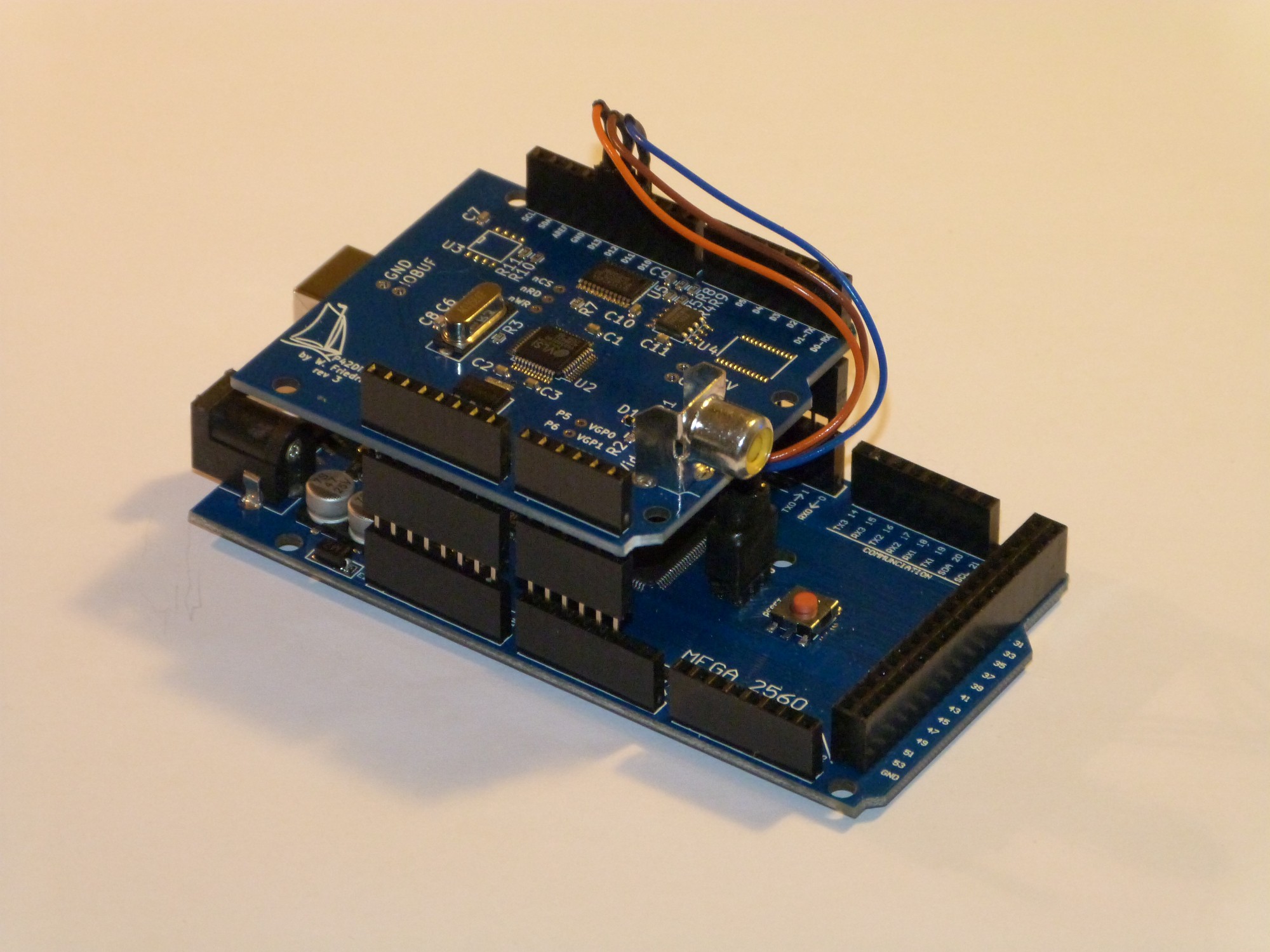
02/28/2019 at 01:54 • 0 commentsTo use the Video Display Shield with an Arduino Mega or Due, a cable to connect the SPI port to the shield is required. The cable would interfere with the shield, so I had to use an extra set of Arduino headers to raise the shield and open up some room underneath. Here demonstrated with a Mega board.
![]()
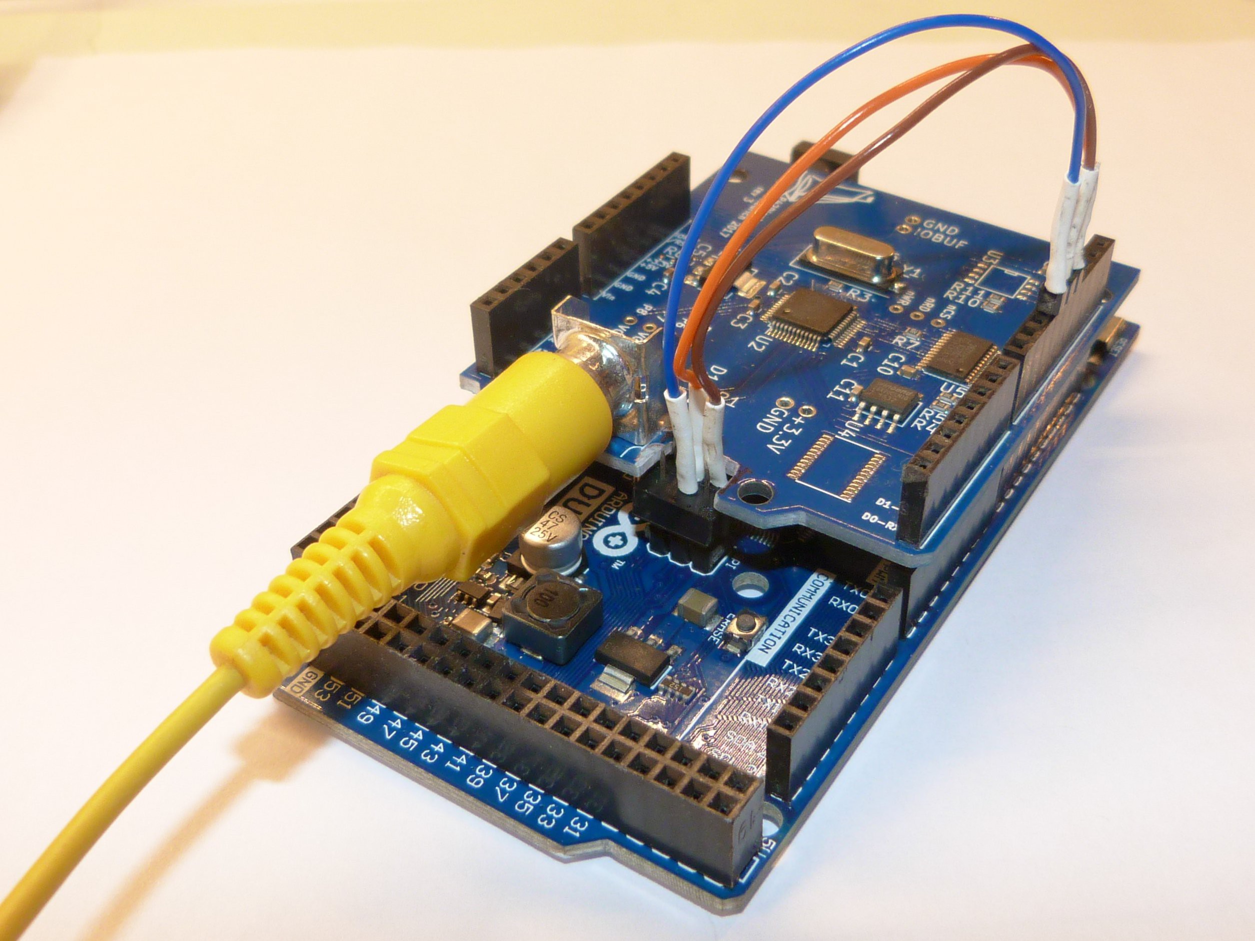
To make the system more compact, I literally hacked the shield (with a Dremel) to provide an open slot to feed the cable through without interference.
![]()
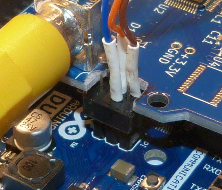
And a closeup for the details.
![]()
Another option would be to use a soft core (bitbang) SPI and assign the standard Uno SPI pins. This depends on the application.
-
Boing Ball Video
04/05/2018 at 00:49 • 0 commentsFinally I have got the animation demo with the famous Amiga Boing ball running. The video quality is not stunning, but it shows what is possible with very little program overhead once the memory is set up. Information on how to do this will be soon below in the instructions and the code is on Github.
-
Selling on Tindie and docs
03/17/2018 at 01:39 • 0 comments![]()
Finally the Arduino library shows enough features and I have built and tested some modules. The boards have been partly assembled (everything SMD) and shipped from @Elecrow. I added the through hole shield connectors and RCA jack and programmed the character bitmaps into FLASH. Now I have opened my brandnew Tindie store and have stock for sale. Code and documentation can be found on my Github.
BTW, the manufacturing was flawless and communication with Elecrow was delightful.
-
PAL vs. NTSC
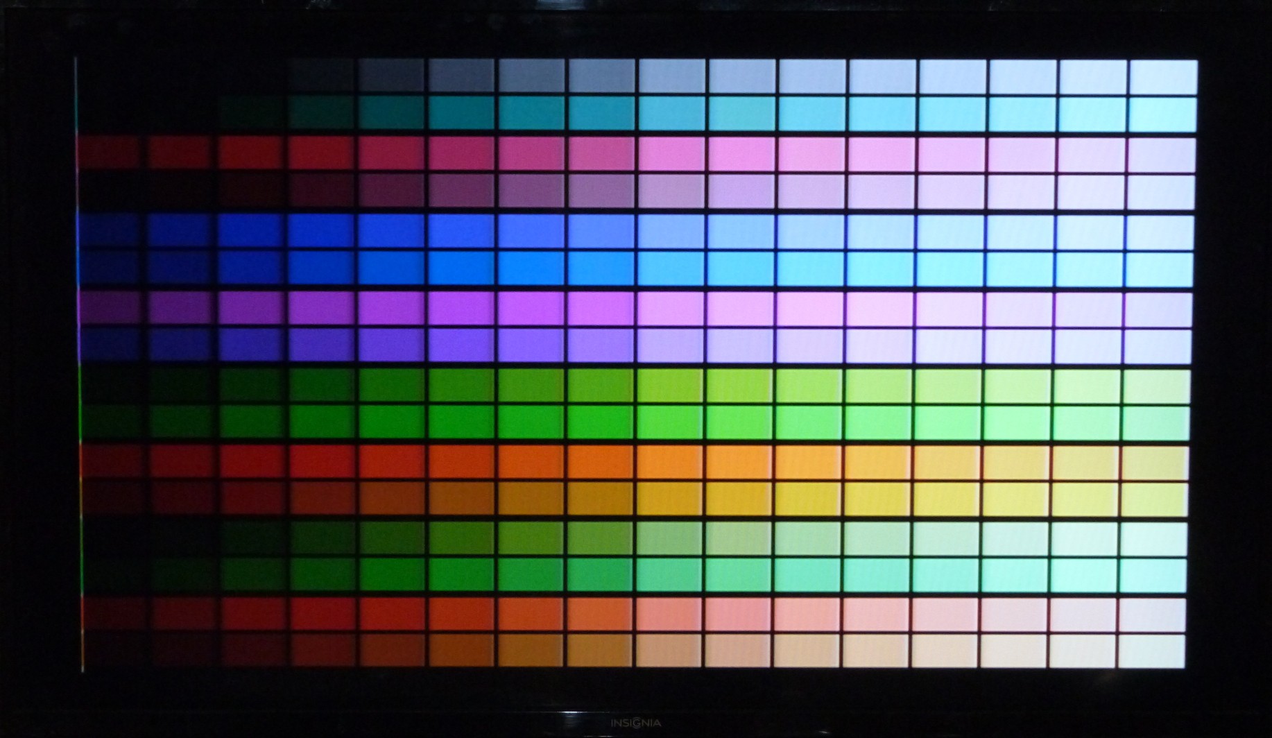
02/25/2018 at 21:02 • 0 commentsNow that I have figured out a setting for similar palettes in NTSC and PAL here are some comparison pictures. All pictures are 8 bit color depth, NTSC resolution is 320x200, PAL resolution is 300x240.
PAL palette
![]()
NTSC palette
![]()
NTSC is a little darker with all settings identical.
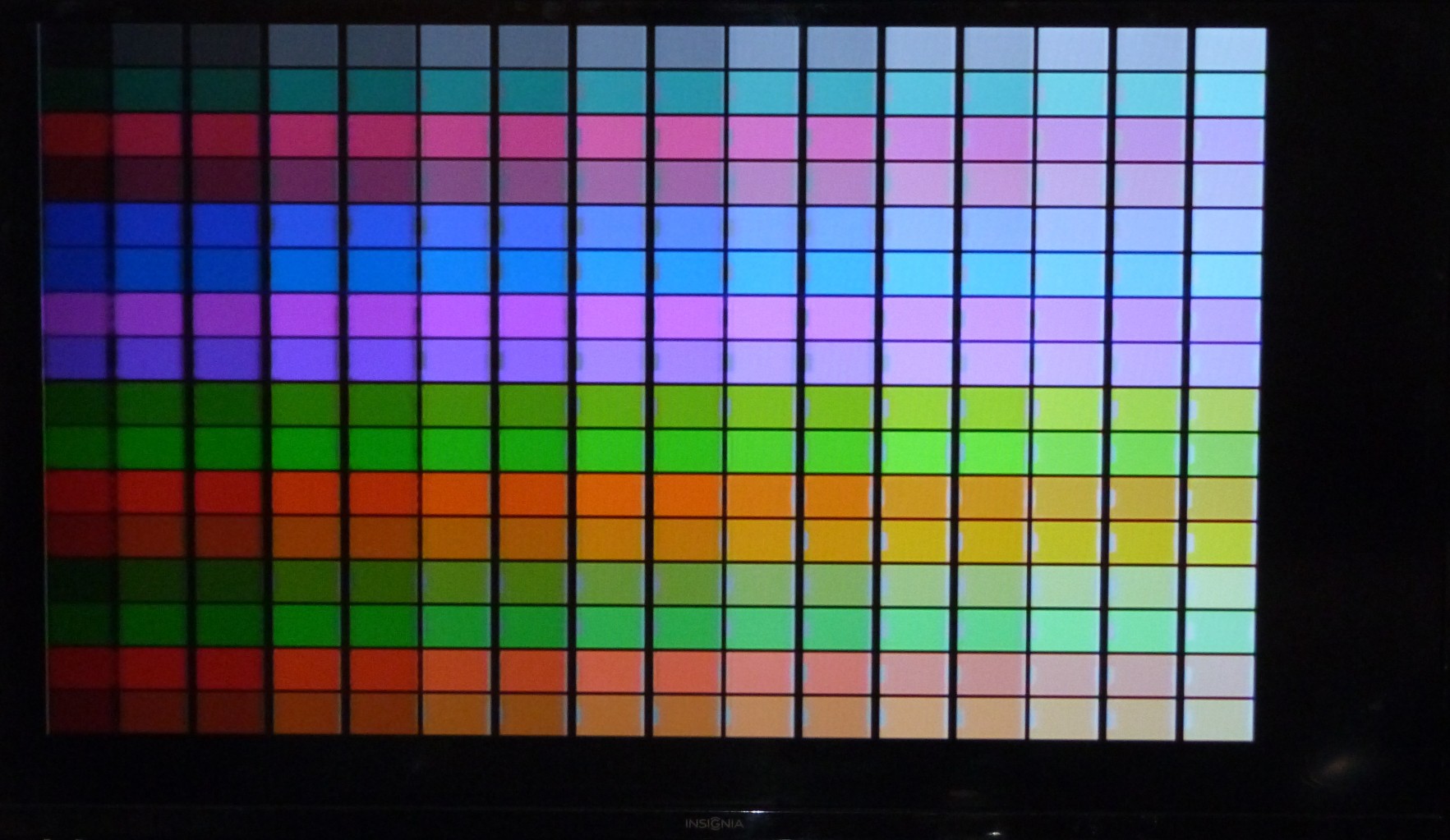
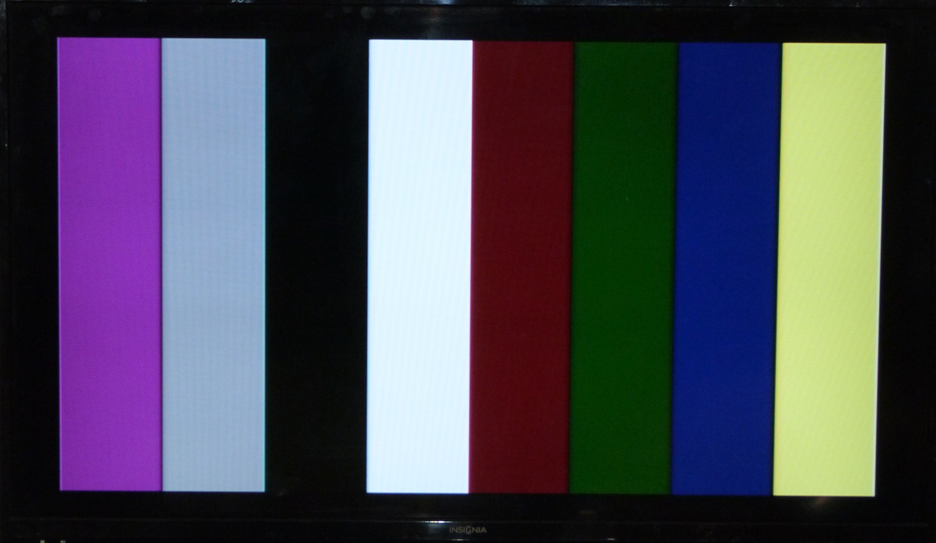
PAL colour stripes
![]()
NTSC colour stripes
![]()
-
SPI for Arduino Mega with Uno shield
02/12/2018 at 01:07 • 4 commentsThe issue: The Arduino Mega has its SPI port mapped on pins 50 to 53, which is on the dual row header at the end of the board. Those pins are not accessible through are regular Uno shield.
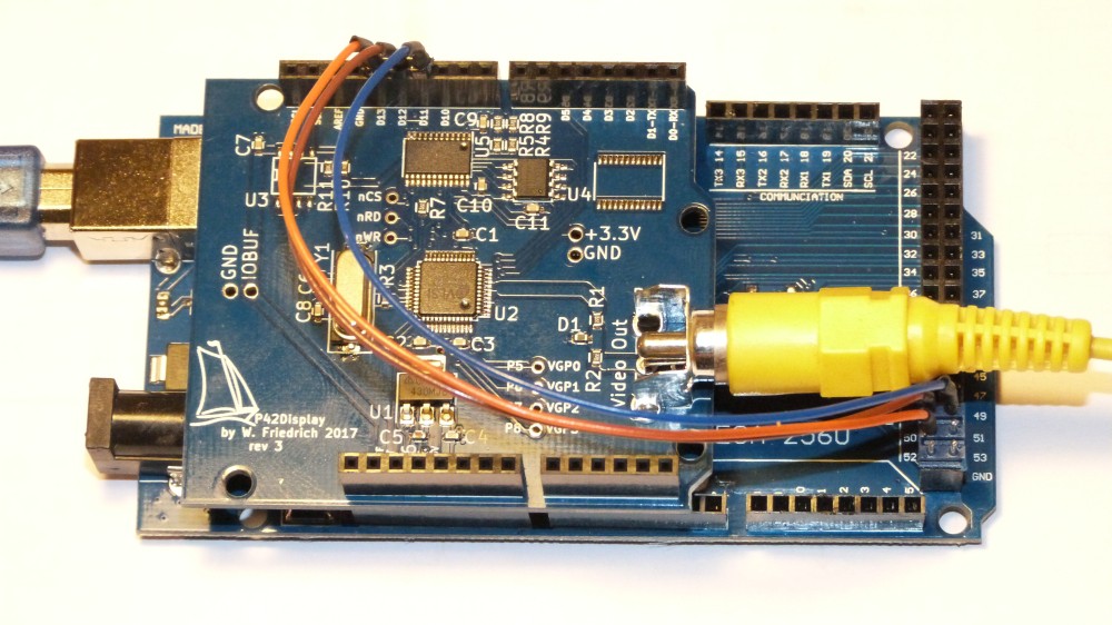
To use my Video Display shield (and any other shield that wants to talk SPI), this is what I did:Connect the SPI communication signals through jumper wires to the shield.
- SCK: Mega pin 52 -> Uno shield pin 13 - orange wire
- MOSI: Mega pin 50 -> Uno shield pin 12 - brown wire
- MISO: Mega pin 51 -> Uno shield pin 11 - blue wire
The slave select pin 53 does not need to be wired, as it is mapped as a normal GPIO in a normal Uno sketch. The picture for the pin numbers 50-51 on the Mega connector is misleading due to the parallax.
![]()
(The RCA connector is not in a ideal location for the wire jumpers. Here is a reason for another spin).
Make pins 11 to 13 on the Mega inputs or tri-stated outputs.
Add the define somewhere in the header file for the shield or at the beginning of the sketch
#define MEGAAdd the code to disable the pins that are used by Uno for SPI in the setup() function
#ifdef MEGA
pinMode(11, INPUT);
pinMode(12, INPUT);
pinMode(13, INPUT);
#endif
This was all I needed to do and the MEGA was happily configuring the Video Display shield and outputting the test patterns.
And the compile log told me, there is lots of memory available compared to the Uno:
Sketch uses 7498 bytes (2%) of program storage space. Maximum is 253952 bytes.
Global variables use 424 bytes (5%) of dynamic memory, leaving 7768 bytes for local variables. Maximum is 8192 bytes.That was easy. (Edit: Well, to easy to not mess it up, pin numbers are now correct, see comments)
-
Revisions 2 and 3
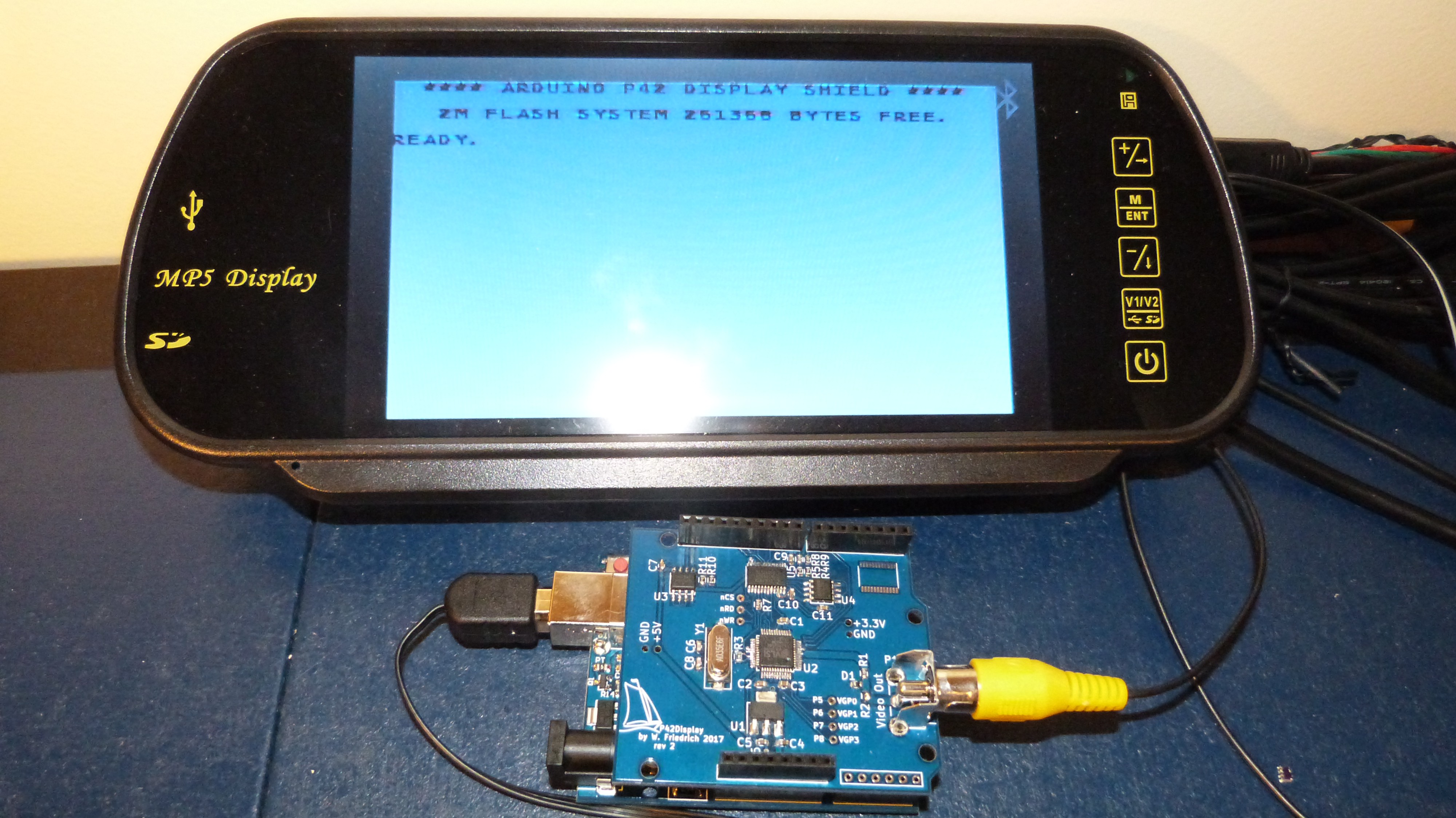
12/09/2017 at 02:17 • 0 commentsThe project made some progress in the last few months. I had board revision 2 manufactured by @Elecrow and got it to work with 'only' 2 wire mods. I had changed the voltage level shifter to a 74LVC4245 and added some protection to the video output. The 2Mbit Flash found a home on the board and is responding to SPI commands. And the IO voltage gets used for the level shifter, this makes the shield compatible to circuits that run with less than 3.3V. Also some progress was made on the software side. I have the configuration for NTSC 320x200 running in my own code. Display of the VLSI test image and text output is functioning.
![]()
Text output on my new 7" display. Now I can work on my desk instead in front of the 40" TV.
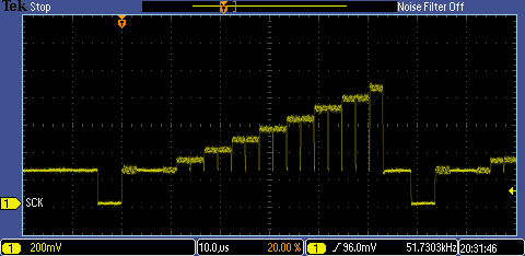
And a scope plot of a nice NTSC video signal displaying the color test image.
![]()
Todo: Add an instruction on how to generate a bitmap font and upload into Flash.
SW todo: Get a PAL configuration and higher resolution set up. Also image display will be a feature.
Rev 3 is removing the wire mods.
-
Some progress
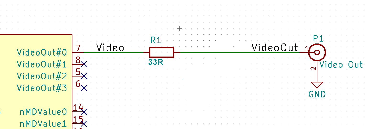
10/01/2017 at 23:20 • 0 commentsI am playing with the hardware to determine the perfect setup for rev 2 of the board. Using this circuit as output driver works best and gives the nicest range from dark to bright color.
![]()
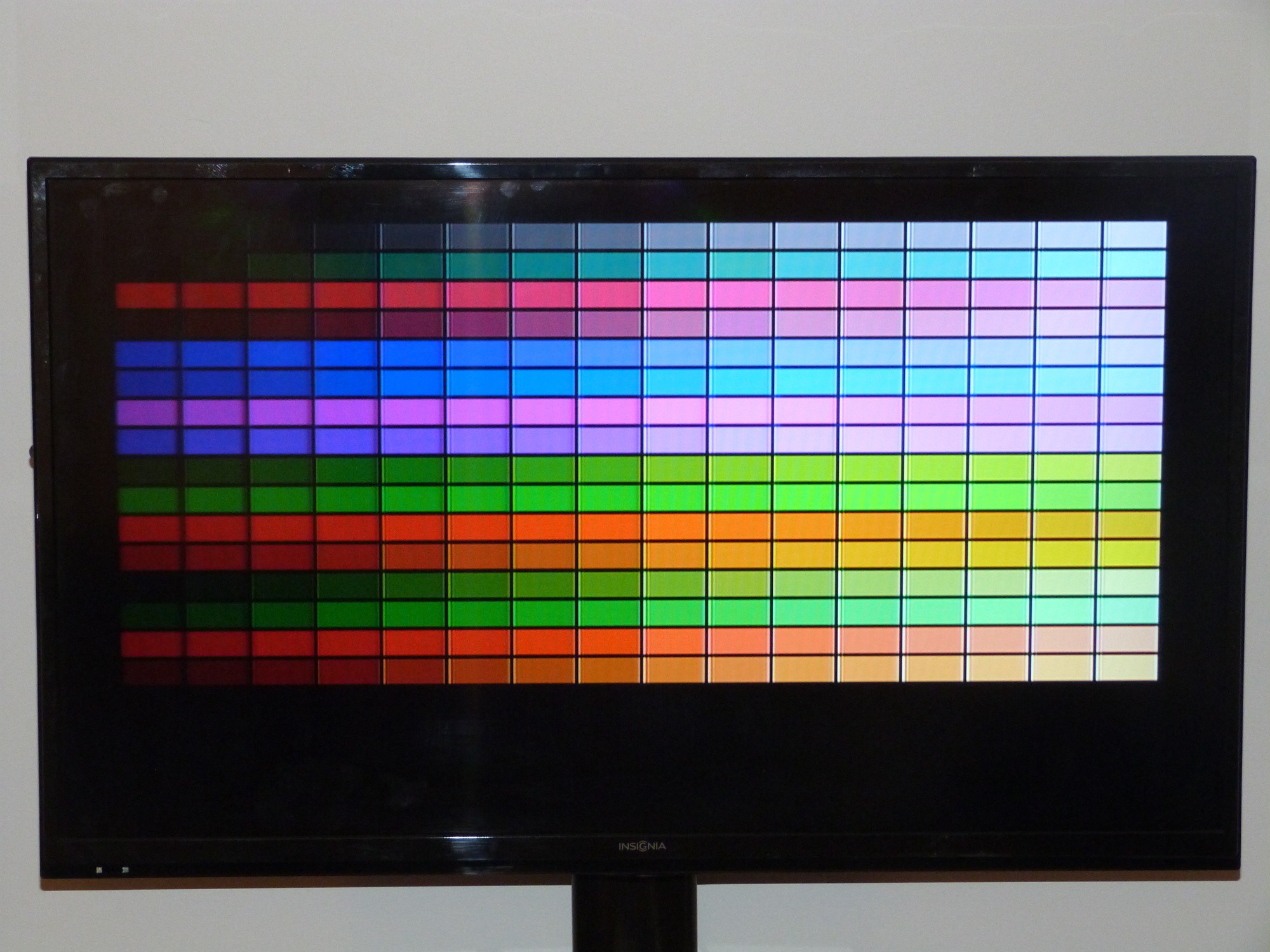
And this is the result:
![]()
So it will be probably 2x 22R with a protection device between on the next board. The output video opamp is still not working, difficult to debug with my scope still in the box.
-
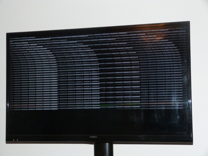
VLSI tech support rocks x2
08/11/2017 at 02:15 • 0 commentsThe folks at VLSI tech support are great. [Panu] and [Kalle] are a big help with HW and SW. They even sent a full Arduino sketch to configure the VS23S010. It does configure the chip corretlyf̶o̶r̶ M̶C̶G̶A̶ 3̶2̶0̶x̶2̶0̶0̶ w̶h̶i̶c̶h̶ u̶n̶f̶o̶r̶t̶u̶n̶a̶t̶e̶l̶y̶ m̶y̶ T̶V̶ s̶e̶t̶ d̶o̶e̶s̶ n̶o̶t̶ f̶u̶l̶l̶y̶ ̶u̶n̶d̶e̶r̶s̶t̶a̶n̶d̶.̶ B̶u̶t̶ i̶t̶ i̶s̶ c̶l̶e̶a̶r̶l̶y̶ v̶i̶s̶i̶b̶l̶e̶ t̶h̶a̶t̶ t̶h̶e̶ v̶i̶d̶e̶o̶ o̶u̶t̶p̶u̶t̶ w̶o̶r̶k̶s̶.̶ N̶o̶w̶ ̶i̶t̶ i̶s̶ j̶u̶s̶t̶ a̶ m̶a̶t̶t̶e̶r̶ o̶f̶ t̶h̶e̶ r̶i̶g̶h̶t̶ c̶o̶n̶f̶i̶g̶u̶r̶a̶t̶i̶o̶n̶ o̶r̶ t̶h̶e̶ r̶i̶g̶h̶t̶ v̶i̶d̶e̶o̶ ̶m̶o̶n̶i̶t̶o̶r̶.
![]()
With the help of VLSI tech support I had my facepalm moment for the week. Just from this picture they could tell me, that I had the crystal for PAL video mounted and not for NTSC (displeasure for some many different standards for everything). Fixing that and getting the video out termination right got me this result. YAY. Now it's only 1s and 0s and a lot of typing to program a graphics engine.
![]()
NTSC/PAL Video Display Shield
An Arduino NTSC/PAL video display shield with integrated framebuffer and composite video output.