-
1Step 1
Straighten out the middle section of the copper pipe.
Putting it in a vise with jaws shorter than the pipe itself and repeatedly just slightly crushing it works well.
Center the pipe in the vise so the ends stick out. It's less work when you connect your hoses if you don't touch the ends.
Tighten, loosen, rotate 90 degrees, repeat.
You'll need a mostly planar surface to solder to later on.
-
2Step 2
Get a breadboard and put a row of header pins in it.
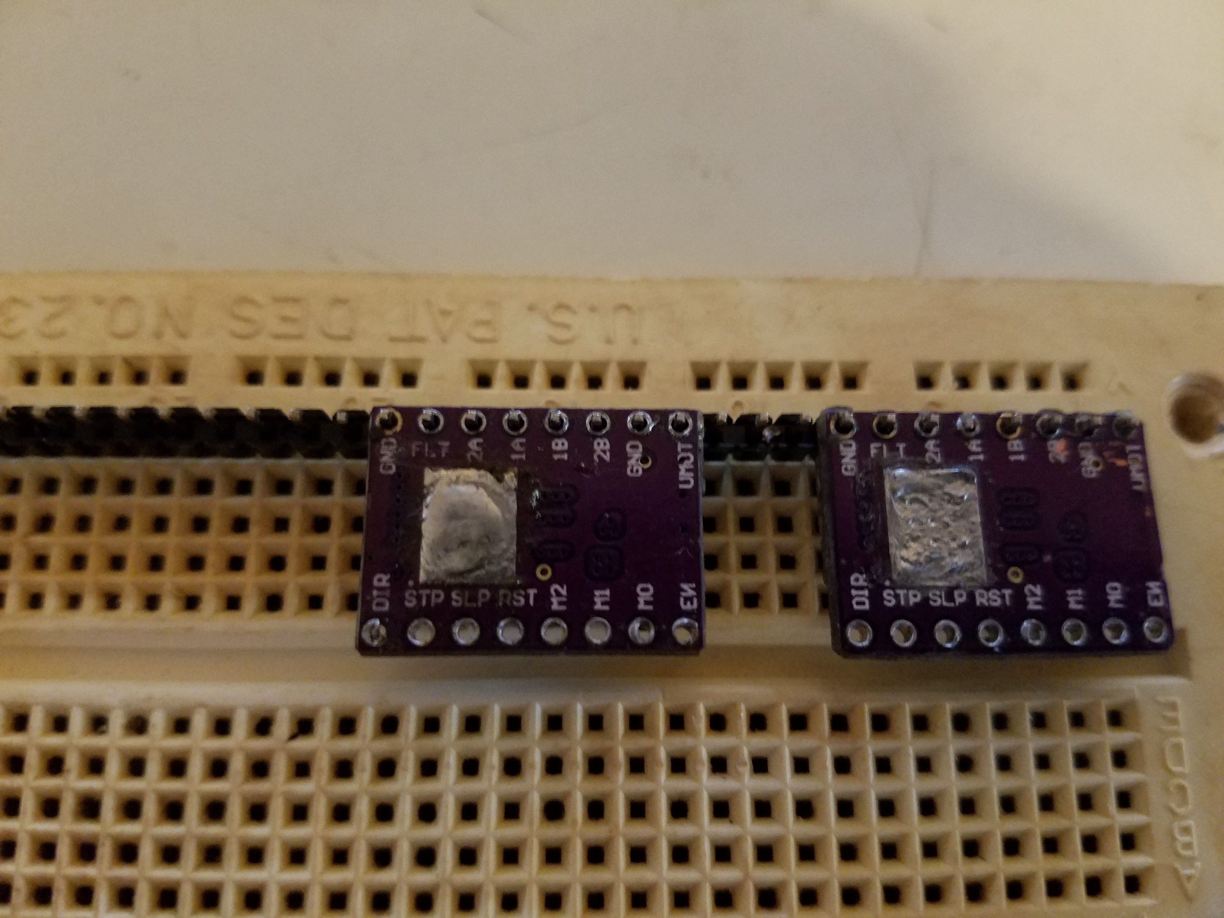
Put your DRV8825 modules upside down on the header pins at a spacing that makes you happy. Do not solder them on.
![]()
Place your copper pipe next to the modules, and mark the pipe in the areas where the exposed backplane of the modules lines up with the pipe.
-
3Step 3
Take the pipe back to the vise, and slightly crush the areas of the pipe not marked.
The pipe is soft enough to do this with just a pair of pliers, but you'll drive yourself mad trying to keep it straight then.
You are creating a raised bump in the areas which need to contact the modules.
-
4Step 4
Put the pipe back in the vise, with the raised/low areas facing up now.
File down the areas in between, making a nice sharp transition to the raised areas.
File down the raised areas, so they are planar with the top of the vise, and with each other.
-
5Step 5
With a good wattage (40w or so) soldering iron, tin the bottom of the IC pad on the modules.
For good heat dissipation, the modules have 2 entire layers of copper connected to this ground plane. By the time you have that pad hot enough to solder to it, the entire module is also at that temperature.
So.. be gentle. The only thing holding the components to the other side at that point is surface tension. The low ESR cap will go first..
-
6Step 6
Tin the raised areas of the pipe. You will probably need a torch for this as it is quite thermally conductive.
-
7Step 7
Place the pipe across the modules, centering the two tinned areas for each module.
Heat the pipe with a torch, until it slumps into place. Again, be gentle as the components on the other side are just clinging there.
Solder a ground wire to the pipe while you are at it.
Heating the ends alternately worked well and prevented burning of the module PCB's.
-
8Step 8
Solder your hookup wires.
You won't need to run the Vmot ground, as the wire you soldered to the pipe is now the ground.
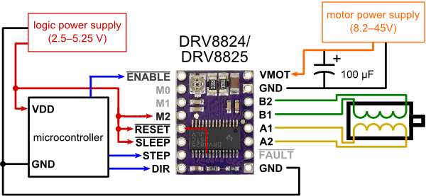
The minimal wiring configuration for the DRV8825's can be found on the Pololu website, but here is the wiring we used.
![]()
This configuration will hardwire the chip for 1/16th microstepping (as it ties M2 high).
The NOT-ENABLE line allows you to use a pin to turn them all on/off. It's held low by an onboard resistor, and driving it high disables the chips. In other words, not hooking it up works too.
The small red line over the chip is a hookup wire connecting from NOT-RESET(logic high) to pin 19 (decay select) and puts the chip in 'fast-decay' mode. Fast-decay mode can result in an annoying hissing sound from the steppers, but ultimately gives you better quality as it eliminates some microstepping related artifacts. We wired ours up to a pin header instead so we could use a jumper to experiment. It's a change I would recommend.
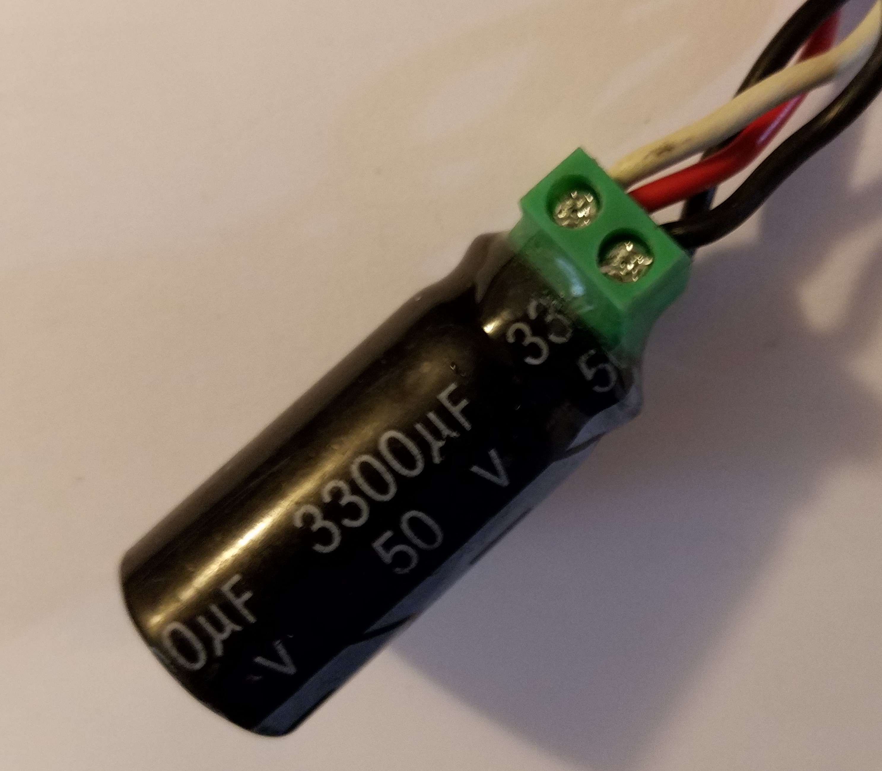
You are also supposed to add an external bypass electrolytic capacitor across Vmot power, and pretty close to the chip. This is to suppress the large LC spikes the chip causes when switching the mosfets. Without a bypass capacitors, you can easily exceed the voltage rating of the driver's power mosfets and pop goes the chip. We just used heavier hookup wire and a single, much larger than needed capacitor, and located it a few inches away. Seems to work.
Soldering a screw terminal to the bypass capacitor, and encasing the connection in epoxy made it reusable.
![]()
Arcus-3D-M2 - Liquid Cooled Stepper Drivers
Got moving water? Might as well use it.
 MasterOfNull


Discussions
Become a Hackaday.io Member
Create an account to leave a comment. Already have an account? Log In.