 Jan Petrik
New PCB revision is under way. I'm incorporating bugfixes from testing, and adding some minor stuff. Errata list is here.
0%
0%
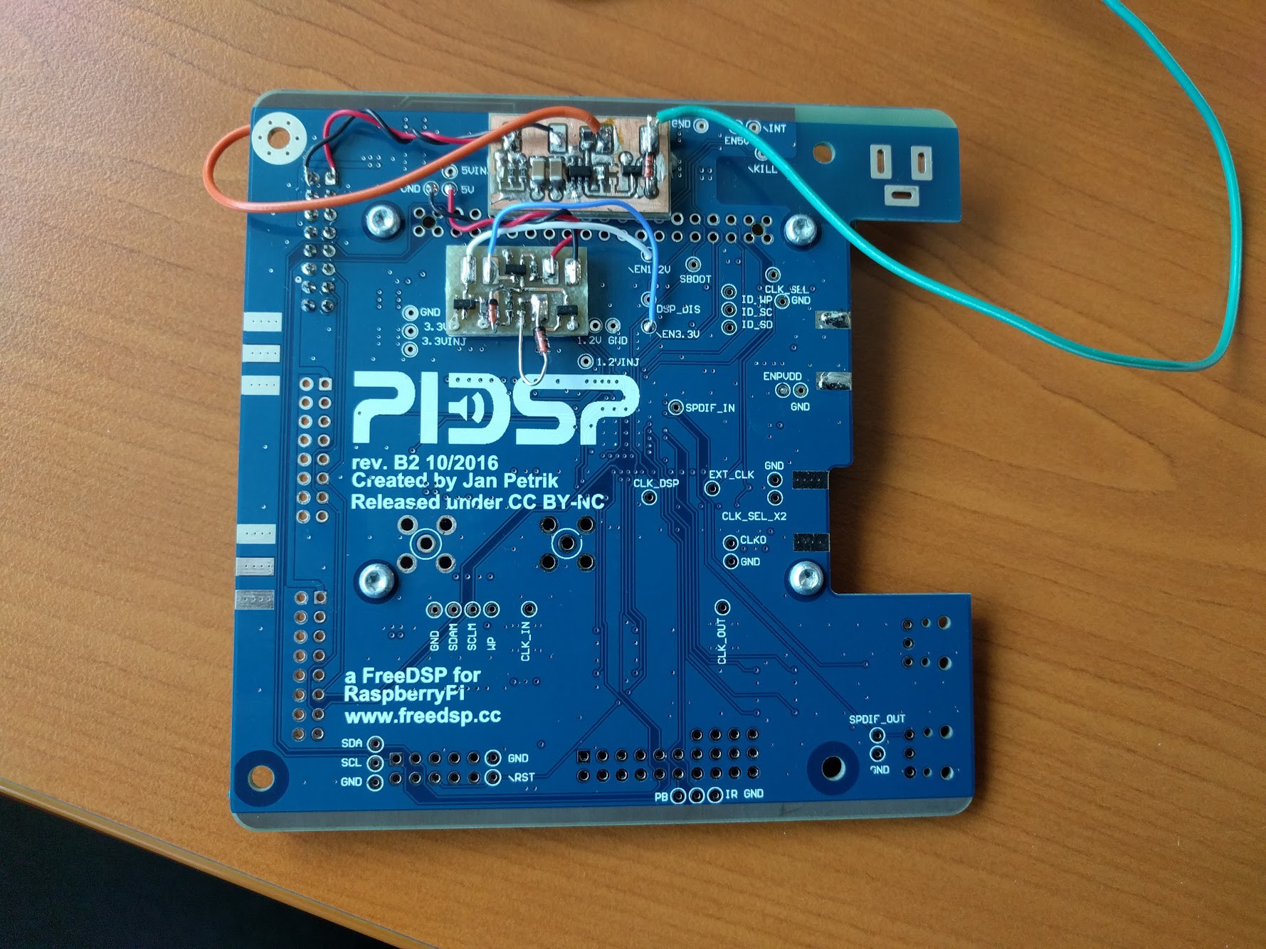
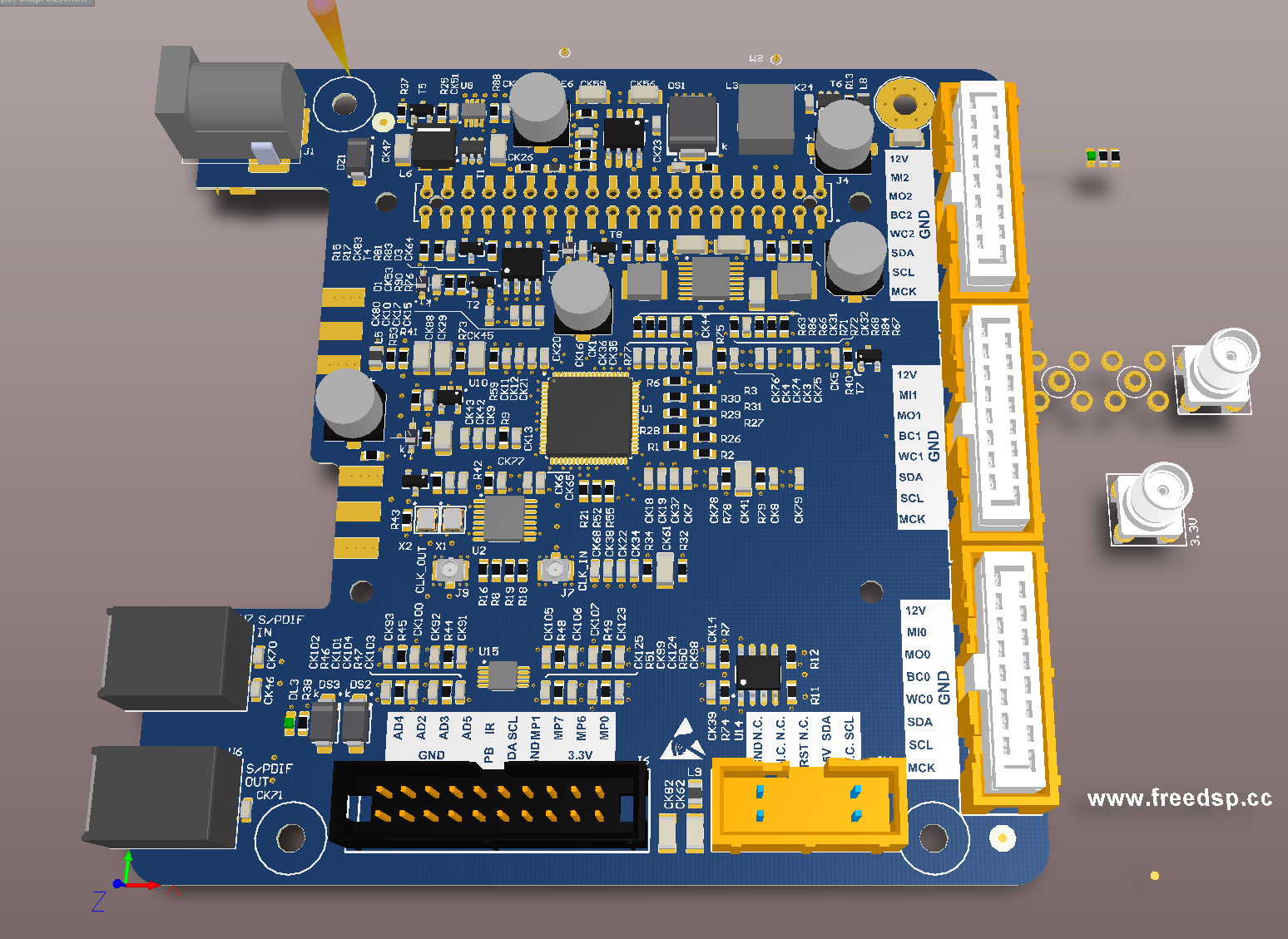
PiDSP
Perfect DSP for your loudspeaker project. Add Raspberry Pi for playback capabilities
Become a Hackaday.io member
Already have an account? Log in.
Just one more thing
To make the experience fit your profile, pick a username and tell us what interests you.
Pick an awesome username
hackaday.io/
Your profile's URL: hackaday.io/username. Max 25 alphanumeric characters.
Pick a few interests
Projects that share your interests
People that share your interests
 NuclearPhoenix
 mkdxdx
 OzQube
 High Altitude Ballooning!