Jan Petrik
-
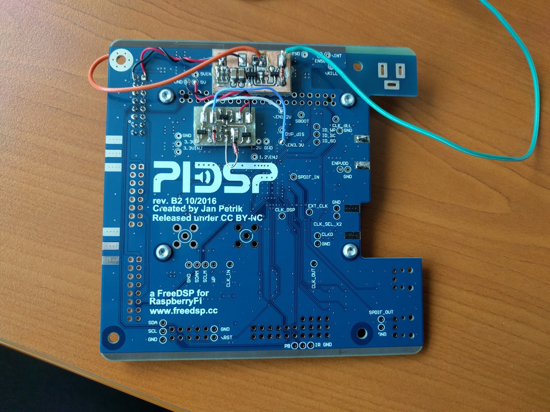
Testing the modules
08/31/2017 at 17:28 • 0 commentsHello, sorry for the summer break!
Anyway, I've tested the new sequencing and high side switch, both perform nicely.
![]()
-
High side switch + AMA
06/12/2017 at 20:37 • 0 commentsHi,
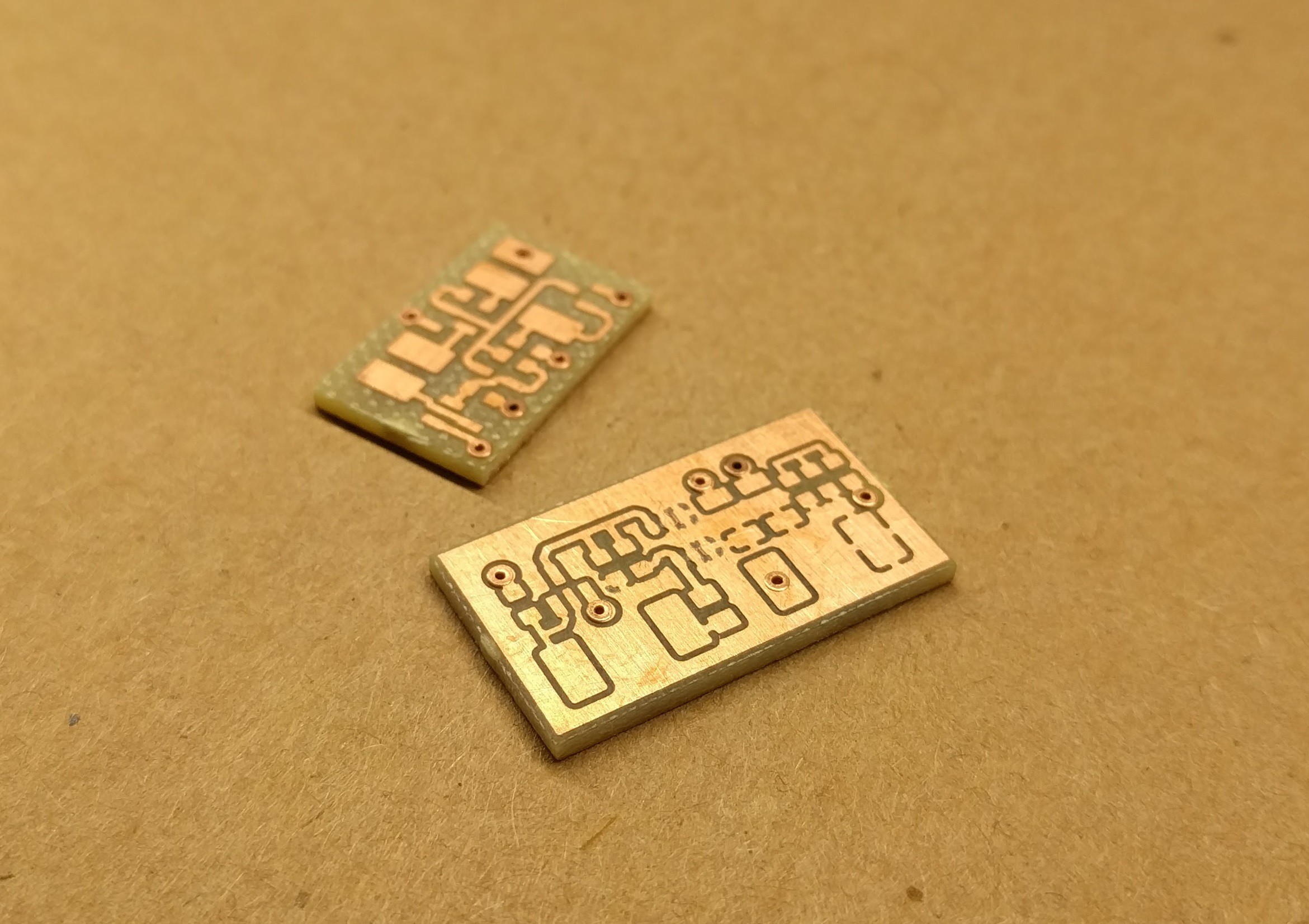
With B2 revision, there is no provision for powering down expansion board s(ADC/DAC etc.), which is pity. For B3 revision I've designed simple high side switch. Before I close the pcb design, I just wanted to test the switch, so I lets have some test-boards:
![]()
Second board is new and better power sequencing - resetting diodes and some minor tweaks.
Also we will have a AMA on 13.06. So if you feel like, please stop by!
-
More inductor testing
05/18/2017 at 16:51 • 0 commentsHi,
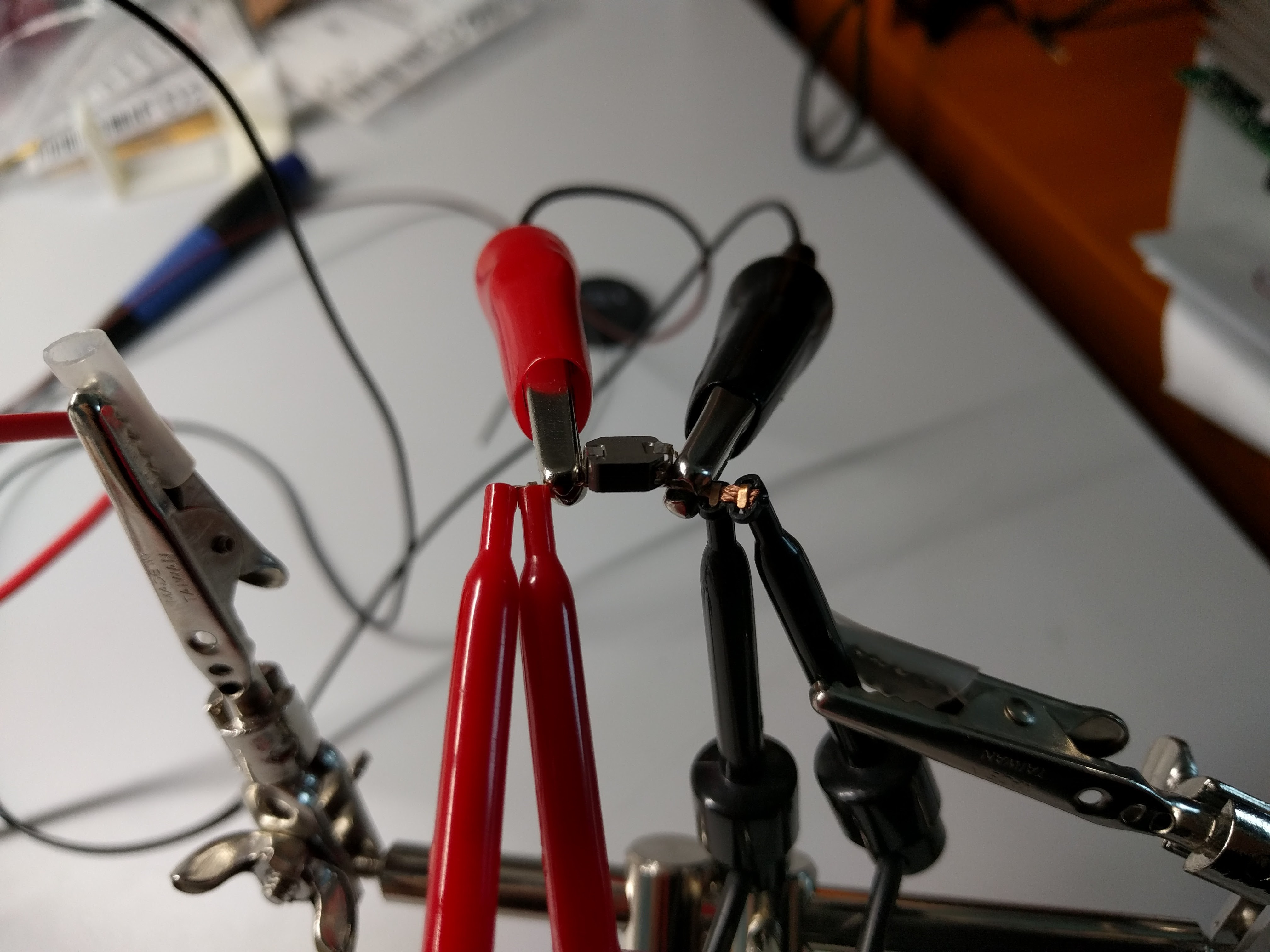
thx to my friend(thank you Honza) and his LabView skills I was able to do some crude C/W testing of the inductors. Test were rather rough - no climatic chamber/box, just a programmable power supply and constant power script in LabView. The winner is 7443340330(not on pictures), with cca 7.25C/W. The original part has C/W roughly twice as big. I have the new part soldered on one of blue boards and ready for some more testing :)
Layout is almost done, I'm going trough DRC checks and pondering about some footprint updates. Also two variants of rotary encoders are on the way - one from bourns, one from Alps.
Question for you guys (and gals.) ), do you like dents for volume control?
Take care,
Pitrsek
![]()
![]()
-
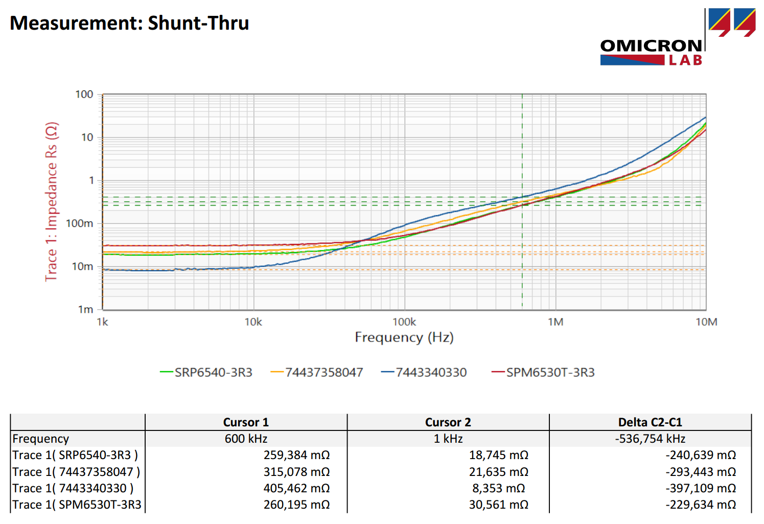
Inductor losses and other news
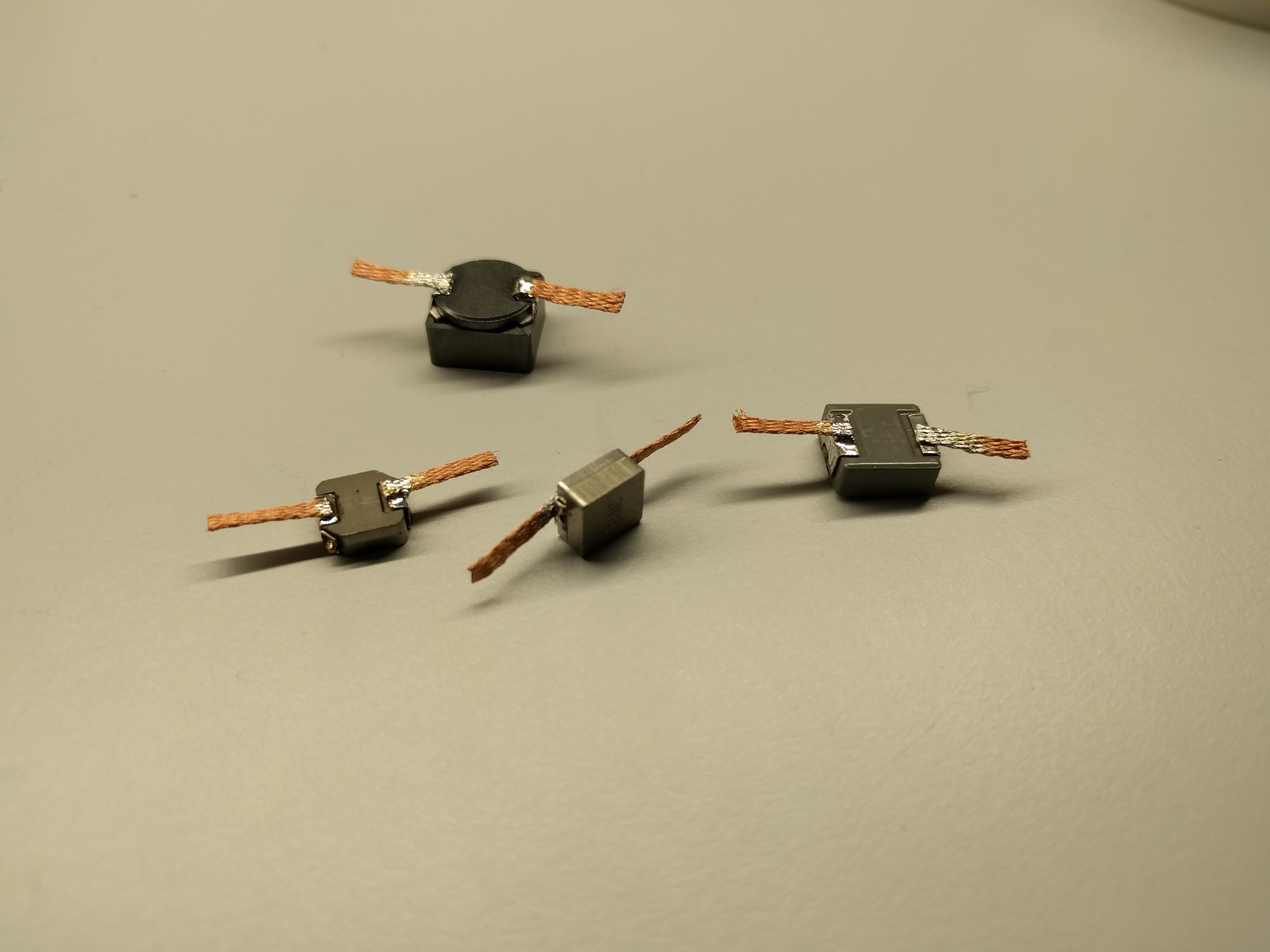
04/24/2017 at 22:37 • 0 commentsIt turned out that new inductors are not really better than old one(SRP6540-3R3). At least comparing real part of impedance (the part that is responsible for losses). One of the WE part is 4.7uH instead of 3.3uH. WE design tool was quite certain that I can get away with it. We'll see :)
![]()
They may be cooler than the original part, due to having bigger size/better cooling ability. Measuring C/W is next on the list + in circuit testing.
I'm leaving for OMICRON Lab Power Analysis & Design Symposium tomorrow. Last year was rather nice, hopefully this year will be even better. Then I'll be off for some traveling on weekend. So no more updates from me for rest of the week.
Mjjg from DiyAudio has received his PiDSP, so he can continue with linux driver development. Also one of my friend is joining in on driver development. So driver team is twice the size of HW team :)
Oh, and I've ordered enclosure and started working on the front panel design.
And that would be all for today.
P.S.: I'm still looking for quality mechanical rotary encoder with smooth action. I've tested just few, but so far it seems that optical ones are in different league. The feel of optical encoder is really nice...
-
Tip for quality rotary encoder wanted
04/19/2017 at 18:56 • 0 commentsHi,
I'm looking for a quality rotary encoder with switch, any recommendation?
Also new inductors arrived today, I should have impedance measurements tomorrow.
-
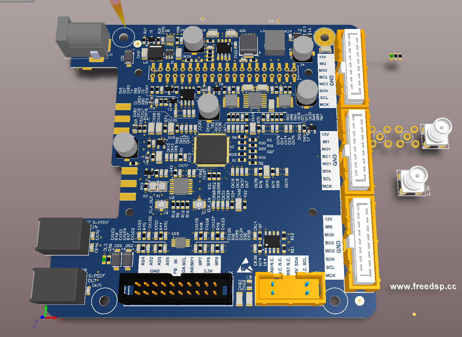
Cleaning-up the layout
04/17/2017 at 14:05 • 0 commentsStill some stuff to clean-up, but PCB starts to look quite all-right :)
![]()
-
Sins of 5V buck..
04/14/2017 at 14:55 • 0 commentsStill Fixing the stuff I missed on last revisions.
One of the more shameful mistakes was thermal design of main 5V buck. It could not deliver 3A with temperatures I would consider reasonable.
I kinda did not pay enough attention to small print in the datasheet |O. Go and take look at PCB that is used for specifying package thermal resistance, that PCB is bigger than you would expect...
I sandwiched buck be
tween edge of pcb and RPI connector. I missed my goal of 3A output by about half an amp. Also I did not verified used inductor beforehand, AC losses were way to high. So for next revision I've improved thermal design for buck and diode. Since I have a little more board estate I can go for a bigger inductor. Samples are on the way(WE 74437358047). And I'll test the inductor before sending boards to production.
I've also discovered that I did not performed "remove unused pad shapes", so there was not really much copper in the ground plane in between RPI connector. That compromised heat transfer into the rest of the board. That is fixed now, so hopefully we'll get better cooling. I'll probably go for 35um copper thickness on next PCB as well - to see the effect of changes. As you can see the difference in web width is quite big - actually now its more than twice the original width....
Old:
![]()
New:
![]()
-
No more collision
04/12/2017 at 19:40 • 0 commentsNo more colliding of SD card and freeDSP connector. Also I think I can increase inductor size :).
![]()
-
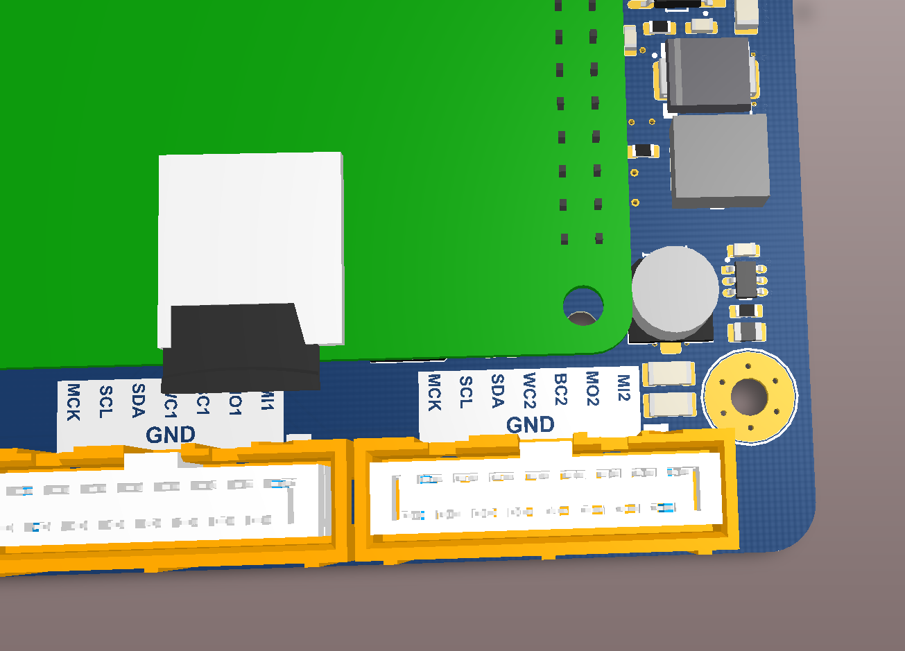
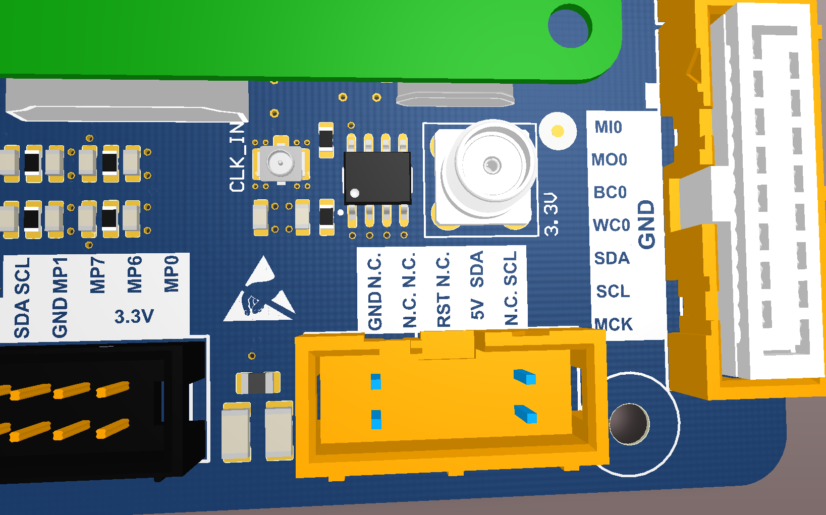
Better silk-screen
04/12/2017 at 19:38 • 0 comments![]()
Going trough the errata list. Among many other things, we can now power down boards that are connected with freeDSP connector, you can use cable relief with middle connector(no more colision with RPi), and we have better connector silk-screen.
PiDSP
Perfect DSP for your loudspeaker project. Add Raspberry Pi for playback capabilities