Fred Fourie
-
Versions... (2025)
6 days ago • 0 commentsHere follows a quick review of the PCBs/Electronics I have used for the project up to now. The versioning follows a loose numbering conventions, but major versions get a fish name in alphabetical order.
Version 0
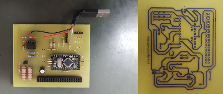
Home etched PCB, ran off a power bank that needed a current draw to stay active. Current draw was generated with a dummy load on a 555 timer to keep the power bank alive. Home PCB etching is extremely satisfying, although the rise of the Chinese PCB manufacturer for the hobbyist has made this practice nearly obsolete, I highly recommend giving it a try.
![]()
Version 1 (Albacore)
First PCB. This was supposed to be an ATMega32U driver board. It proved to be too complex- too much too fast. This one did not really get off the ground at all. There were way too many peripherals and not enough focus on robust core functionality.
![]()
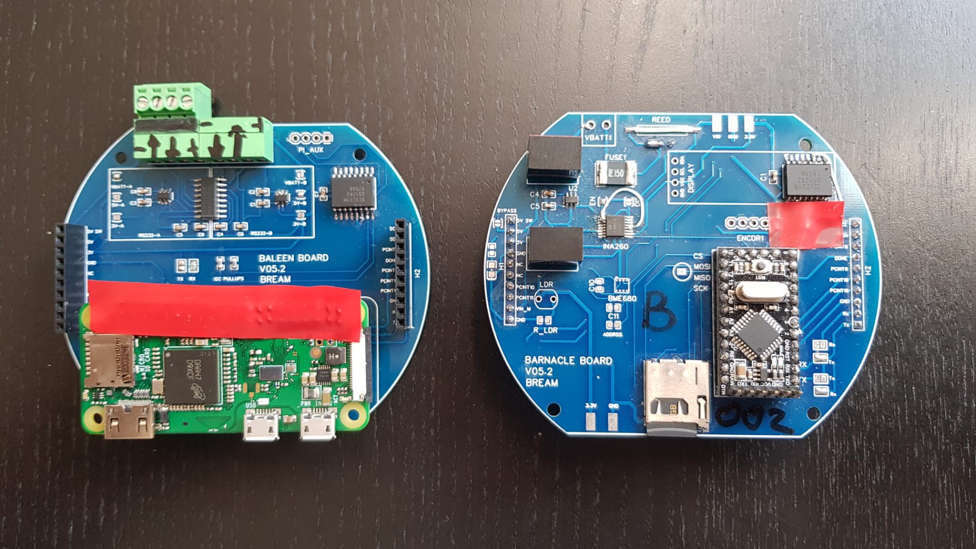
Version 2 (Bream)
The first stacking board approach. Version numbers on the silkscreen don't match this naming convention. This version did see some time in the water, but had a few small hardware fixes. Ultimately- it worked
![]()
Version 3 (Cod)
This was a iteration of the two board design ended up being one of the most successful versions as it saw the most time in the field ( See: "A short biased discussion on alternatives Part #2" ) . The RS232 interface on the Pi proved to be very useful for a bunch of other applications.
![]()
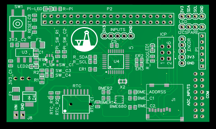
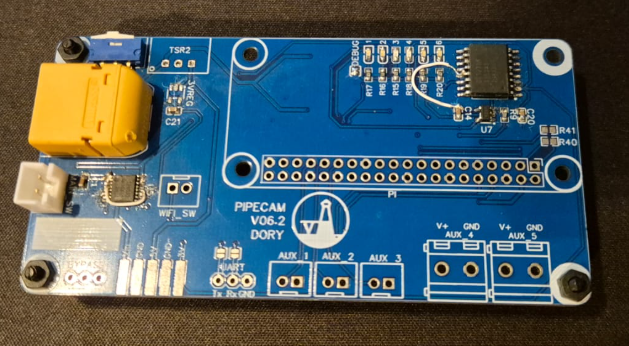
Version 4 (Dory)
From this version things get weird. Although Dory is my favourite PCB for this project so far, it was not successful. The new design gets rid of the stacking PCBs and of the micro-controller in attempt to simplify the control and especially the setup of the sleep interval.
![]()
Problems were primarily around getting the RTC to operate correctly without a microcontroller managing it. There where some really fun problems there and I would like to re-visit this design.
Version 5 (Elver)
This was part of my brief foray into ESP32 cameras ( See: "A short biased discussion on alternatives Part #1" ). Although I liked the approach and I LOVE ESP32s, I decided that it sucks a bit of the fun out of the project to keep pursuing it. The "off-the-shelf" solutions were actually just not a good enough fit for what I wanted to achieve. I primarily tested Elver on my bearded dragon's tank.
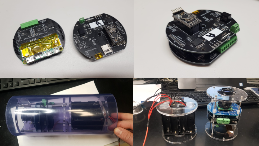
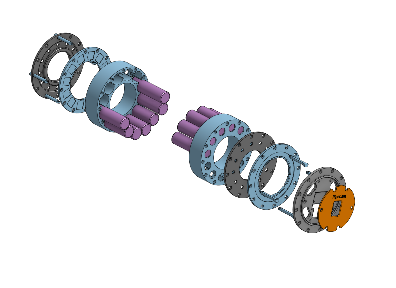
Version 6 (Flounder)
This has been the "current version" since 2023. This is a version where I just use a Witty-Pi on the Pi Zero ( See: "A short biased discussion on alternatives Part #2" ). The Witty-Pi does about 85% of what I wanted to achieve with the "Dory" version and decided to give it a shot. The facts are sometimes "good-enough" is actually just... well... good enough. This also gave me the opportunity to try my hand in addressing some of the mechanical mounting aspects of the project, which is not my strength.
![]()
The next post or two will be around this version of the project.
-
A short, biased, discussion on alternatives Part #2
08/21/2024 at 07:25 • 0 commentsAlthough work on the controller PCBs have stalled, I have been fortunate enough to use the exact hardware in 2 other projects:
1. A remote logger for an oceanographic instrument in Greenland: measure, transmit data, sleep
2. An long term underwater scanning sonar: do a sonar scan of the seafloor, sleep.
The second has been my avenue to produce my first paper and submission to the HardwareX journal, a small bucket list checkbox to tick. Instead of a photo timelapse I was able to generate a timelapse of seafloor changes for 30m over 3 months.
I have been eager to continue with this project again, with a new, improved controller PCB, but as years have passed since I have started the project I decided to check the market. And damn. I found a product that makes my efforts near unnecessary:
The Witty Pi 4 (L3V7)
https://www.uugear.com/product/witty-pi-4-l3v7/
Finding this thing made me swear a lot. I immediately bought one to check out and damn, it really is a near drop in replacement for my controller. UUGear has created an extremely capable companion board for a pi Zero, with some really useful and sensible software too.
If anyone ever in the future looks at this project and wants to build something similar, look no further for handling your Pi sleep cycle. Forget all the ploys I have mentioned before- even the TPL5111.
There are of course minor compromises, but really, everything you need to make a sleeping pi is here. My board of choice, the Witty Pi 4 L3V7 comes at a cost of about 24 EUR.
-
A short, biased, discussion on alternatives Part #1
08/21/2024 at 06:46 • 0 commentsAlternative to the Pi
After the availability issues of the last 2 years Raspberry Pi has widely announced that they are “back”.
Unfortunately, for this project the Pi Zero W (and the new successor the Pi Zero 2 W) has returned to the market with a considerable price increase.
The base Pi Zero W now is anywhere between 17-25 euros with camera modules skyrocketing from 20 euros up.
Although the ~60 euro that you will spend on getting a decent base up and running is still relatively low cost, I started looking for alternatives.
Pi is still SBC King
When it comes to finding a single board computer competitor for the Pi: There simply isn’t one that can compete with their price point. (and community support)
https://www.makeuseof.com/what-is-the-cheapest-single-board-computer/
Although I very much appreciate the higher power and industrial new generation Pies, the niche that the Pi Zero filled had seems to have fallen by the wayside.
So if not a SBC, what then?
ESP32 Cameras
The ESP32 has been my go-to microcontroller for a while. It’s low cost and extremely versatile. There have been loads of comparisons done between it and the “new” Raspberry Pi Pico but the native wifi/BLE of the ESP32 is a massive advantage.
https://www.makeuseof.com/raspberry-pi-pico-vs-esp32-microcontroller/
In recent years several dedicated ESP32 camera boards have popped up on the market
https://makeradvisor.com/esp32-camera-cam-boards-review-comparison/
at prices from 9-20 euros (camera included) so I decided to invest some energy into investigating this as an alternative.
Criteria I have decided to study are:
- Image quality
- Sleep power draw
- Peripherals
AI Thinker ESP32-CAM
The first board that caught my eye was the AI Thinker ESP32-CAM and will be the board I will be reviewing in detail.
https://randomnerdtutorials.com/esp32-cam-ai-thinker-pinout/
https://docs.ai-thinker.com/esp32-cam
Right off the bat this looks great.
Small module, SD Card, 2MP camera and LED “flash”. These are peripherals that I would need for this project.
So let's review this against our criteria:
1. Image quality
The 2 megapixel OV2640 camera is probably not going to be good enough for the underwater environments, but doing some research has shown that the board is actually compatible with several other camera modules, including the 5MP OV5640, which might be good enough.
Previous tests with the Pi Cameras has shown that the difference between the 8MP and 12MP cameras are not that big and that the 8MP is good enough. Perhaps the 5MP will still suffice.
The board also matches the 5MP module pin to pin and using the OV5640 as a drop-in replacement seems to work well.
Below is the standard OV2640 (~60 KB file size):
![]()
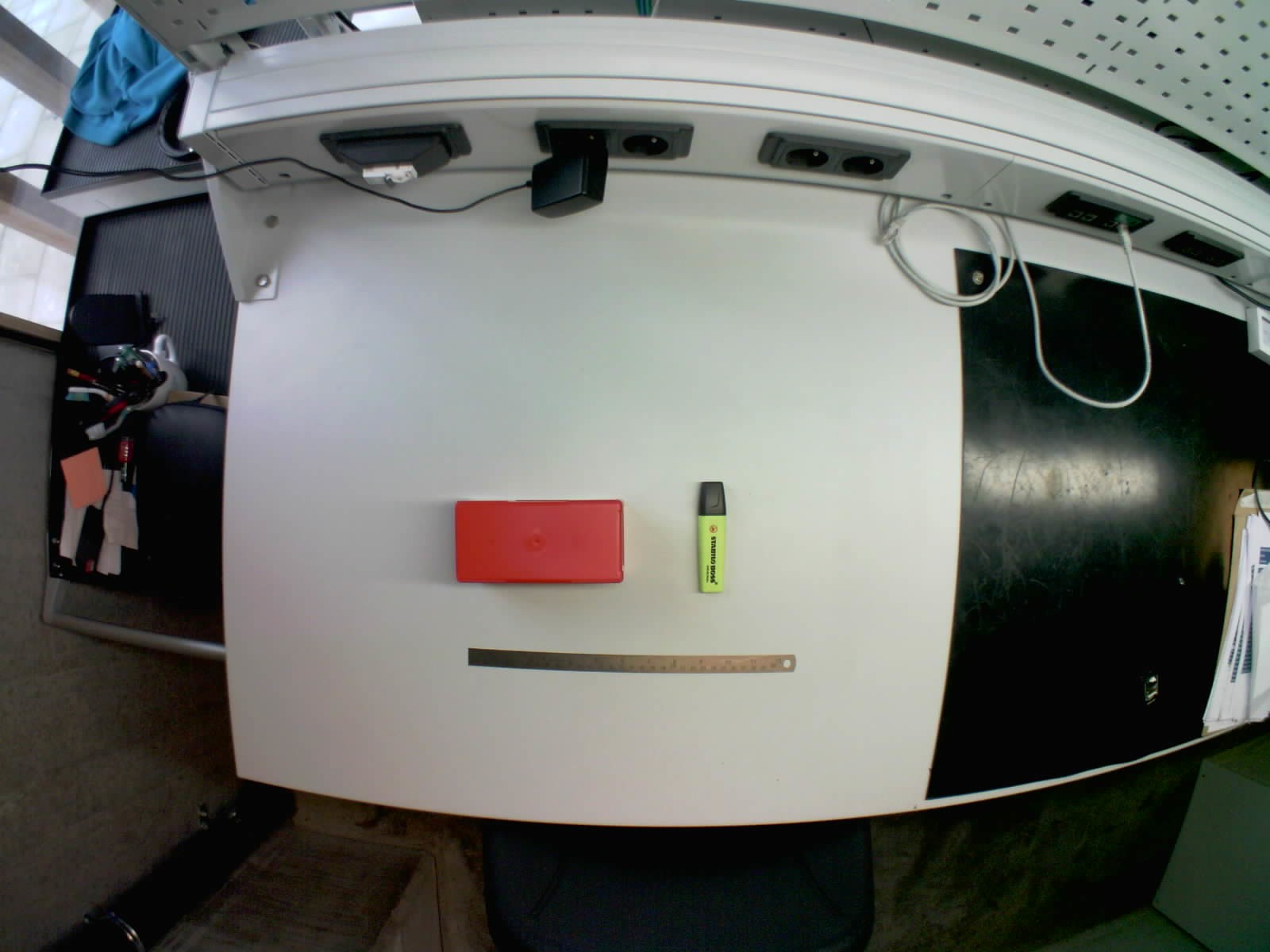
Here is the OV5640, with a fisheye lens from the same distance (~408 KB):
![]()
As you can see it is a massive difference. Certainly the OV5 + fisheye lens is a great combo for landscape or security applications. It is for sure worth looking into alternative higher quality camera modules for compatibility. Below is my quick comparison of alternatives.
Comparing other camera module boards for compatibility:
Manufacturer ESP32CAM WaveShare M5 Timer FLIP M5 Timer Cam module OV2640 OV5640 OV3660 OV3660 MegaPixels 2 5 3 3 ESP32 incl yes no yes yes USB incl no no yes yes SD Card incl yes no no no Price (EUR) 11 18.17 20.5 20.5 Pin 1 2.8V GND 2 GND 3V3 GND 3 CSI_D2 Y4 SIO_DAT 4 CSI_D1 Y3 2V8 5 CSI_D3 Y5 SIO_CLK 6 CSI_D0 Y2 RESET 7 CSI_D4 Y6 VSYNC 8 CSI_PCLK PCLK PCLK PWDN 9 CSI_D5 Y7 HREF 10 GND GND GND 1V2 11 CSI_D6 Y8 3V3 12 CSI_MCLK XCLK XCLK Y9 13 CSI_D7 Y9 XCLK 14 3V3 3V3 3V3 Y8 15 CSI_1.2V 1.5V 1V2 GND 16 CSI_HSYNC HREF HREF Y7 17 1k PWDN - GND PWDN PCLK 18 CSI_VSYNC VSYNC VSYNC Y6 19 CAM_RST RESET RESET Y2 20 TWI_SCK SIO CLK SIO_CLK Y5 21 CSI_2.8V 2.8V 2V8 Y3 22 TWI_SDA SIO DAT SIO_DAT Y4 23 GND GND GND 3V3 24 GND
2. Sleep power drawThe ESP32 typically has great low power capabilities and are super easy to put to sleep. For this project I aim to sleep in the sub milliAmp range.
Power consumption measurements I have done show a sleep current of ~19.1mA and a peak current use (when the picture is taken) of 170mA - 195mA. This is of course too high.
But WHY is it so high?
First of all, the “FLASH” Led is connected to one of the SD card data lines, so it will be active more than desired. This can be rectified by simply removing/desoldering the LED.
Measurements with the LED removed reduced the sleep current down to 5.6mA and peak current to 140mA - 170mA.
So what is causing the rest of the current draw? Let’s look at the peripherals.
3. Peripherals
SD Card
The built in SD Card is fantastic to get from nothing to timelapse very quickly, but there are some very real problems here. First of all there is the old problem (discussed here before) of SD Cards actually being unreliable little power parasites if not managed well. In this case, the power to the SD card is never cut, so this is very likely where +5mA extra sleep draw is coming from.
Additionally, resources online state that the maximum storage that can be handled is 4GB. To test this I loaded the SD card with 2x 3.7Gb image files and ran it. It seems to work okay.
GPIO: There are no real GPIO pins available on this board except for one general use LED pin.
Conclusion
There is of course tons more testing I could have done, but this is how far I got. My honest conclusion is that the ESP32cams are great for cheap camera projects, but the price point comes with limited room for improvements. The "high" current draw and lack of extra IO out of the box is enough to ward me off from future projects. I am sticking with the Pi Zero!
-
State of the project, March 2022
03/21/2022 at 19:01 • 0 commentsState of the project:
- PCB version is currently at V06.04. Code named DORY
- V06.04 is a single PCB with only two external peripherals: a power sensor chip and a RTC
- The new design ditched the external controller altogether
- There is no longer an external SD Card slot
- DORY now has two extra switches for toggling devices.
- DORY features wifi data download, to make testing easier
- A new housing with an external on/off switch was tested and flooded. (more later)
- Camera test have revealed that the benefits of the HQ cameras are not THAT great and that the V2 raspberry pi camera still performs really well
- DORY has not been in the water yet and is currently undergoing low power testing. (Hence no cool pictures as of yet)
Ditching of the micro-controller:
This is by far the biggest change to the project. The old versions of all relied on an external micro-controller (the Arduino ProMini clone) reading an SD Card to determine the sleep intervals.
This meant that, once deployed, there was no way to change this apart from opening up the housing and getting to the SD Card. This was proven a problem in when working in the field.
Further more, a way to use the RTC alone on to do the power switching of the pi was devised. Removing the micro-controller would remove the need for an external SD Card (discussed next), reduce the power and reduce the complexity of the project. Ironically, shortly after this design choice was made, I found that the Robodyn Promini boards which I had used for my previous boards has been formally discontinued.
Removal of the SD card:
Not all SD Cards are created equal. Between brands and individual units, SD Cards differ. This is became very apparent when I started measuring the low-power sleep modes in the previous iterations. Different SD Cards would push the power consumption from a couple of uA to as much as 1mA in some bad cases. While troubleshooting this, I came across this from another inspirational hackaday project:
https://thecavepearlproject.org/2014/09/22/high-sleep-current-problem-solved/
With all of these troubles in mind, I decided to ditch the SD Card.
The Great Silicon Shortage:
It has been incredible to see that usually, easy-to-find components are just globally out of stock. This has pushed the need to redesign the board with less component and towards designing for interchangeable footprints.
DON'T RUSH IT
Over the last hear I had the opportunity to deploy at sea. I quickly made a new housing and introduced a number of "new" components to the housing. This catastrophically failed within minutes of deployment. Mechanical stuff is not my strong point. So next time I should take my time, test the housing.
Alternatives:
If you have landed on this because you are itching to build your own project, similar to this. I have some good news for you. There are off-the-shelf components that will help you get rolling MUCH faster than waiting for this project. The best example I have found so far is the Witty Pi:
https://www.uugear.com/product/witty-pi-3-realtime-clock-and-power-management-for-raspberry-pi/
The near future:
The new DORY PCB is currently undergoing testing, so far all the peripherals are performing as expected and the PCB design seems sound.
The next step will be a redesign of the internals: a battery pack and a set of mountings for the PCB and camera.
And the hopefully! Back into the water she goes!
-
Colour Corrections
05/15/2021 at 21:26 • 0 commentsBecause the current version of the project has no light source, colour correction may be useful in deeper deployments. A simple method for colour corrections was applied that yielded good results.
Scripts obtained from http://www.fmwconcepts.com/imagemagick/uwcorrect/index.php was tested, and the following command gave the best results for this case:
./uwcorrect -m 2 -b 5 -s 10 target.jpg corrected.jp
Then this command was used to write a small batch processing script in BASH:
for f in ./photo/*.jpg
    do f2=${f%.*}_processed.jpg;
    echo "Processing $f as $f2...";
    ./uwcorrect -m 2 -b -10 -s 10 $f $f2
done
The results:
![]()
-
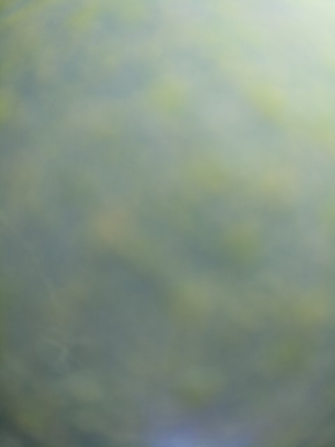
+3 weeks in the harbour: some results
05/15/2021 at 21:08 • 0 commentsRecently, I deployed two cameras in the local docks in very shallow (~50cm) water with a 4 hour day/night interval. The camera were not placed and ballasted well so they did move around too much to allow for a decent time-lapse.
Here are some of my favourite results from that deployment.
![]()
The photo above is with the Raspberry Pi HQ camera through a polycarbonate "lens". The discolouration seen at the bottom was an experimental LED. The LED did not yield conclusive results in this test.
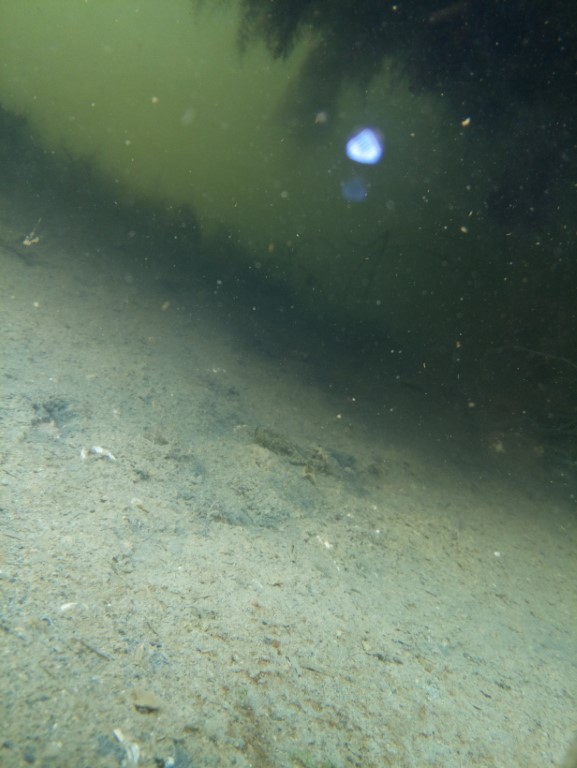
![]()
The photo above is the same scene (roughly) after three weeks in the water. The algae growth on the lens is pretty dramatic.
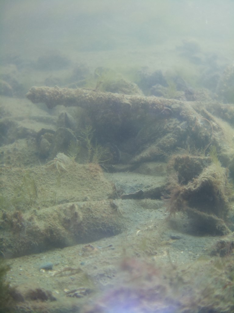
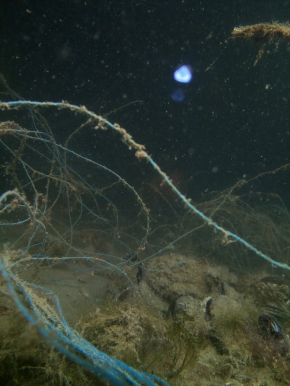
The next set of photos are with the raspberry pi v2.1 camera and a different experimental lens and LED:
![]()
![]()
These show that the 8MP V2.1 camera still produces very good results (although the polluted harbour is very clear) and puts into question the use of the HQ camera at three times the price. Because of better positioning, these images produced by this camera were far more interesting.
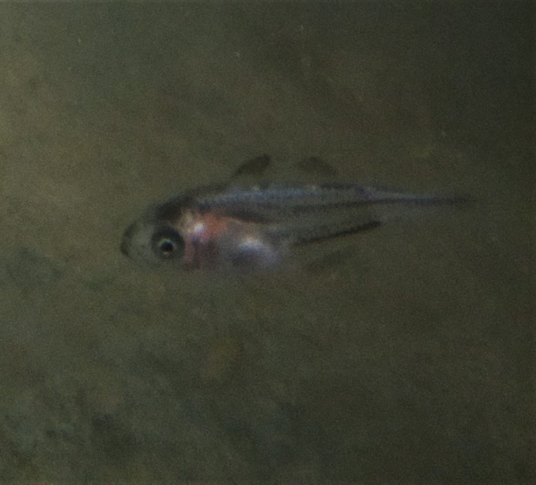
Here are some of my favourite animal sightings in the results:
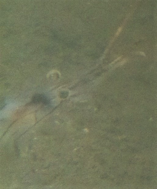
Yet unidentified juvenile fish
![]()
Shrimp:
![]()
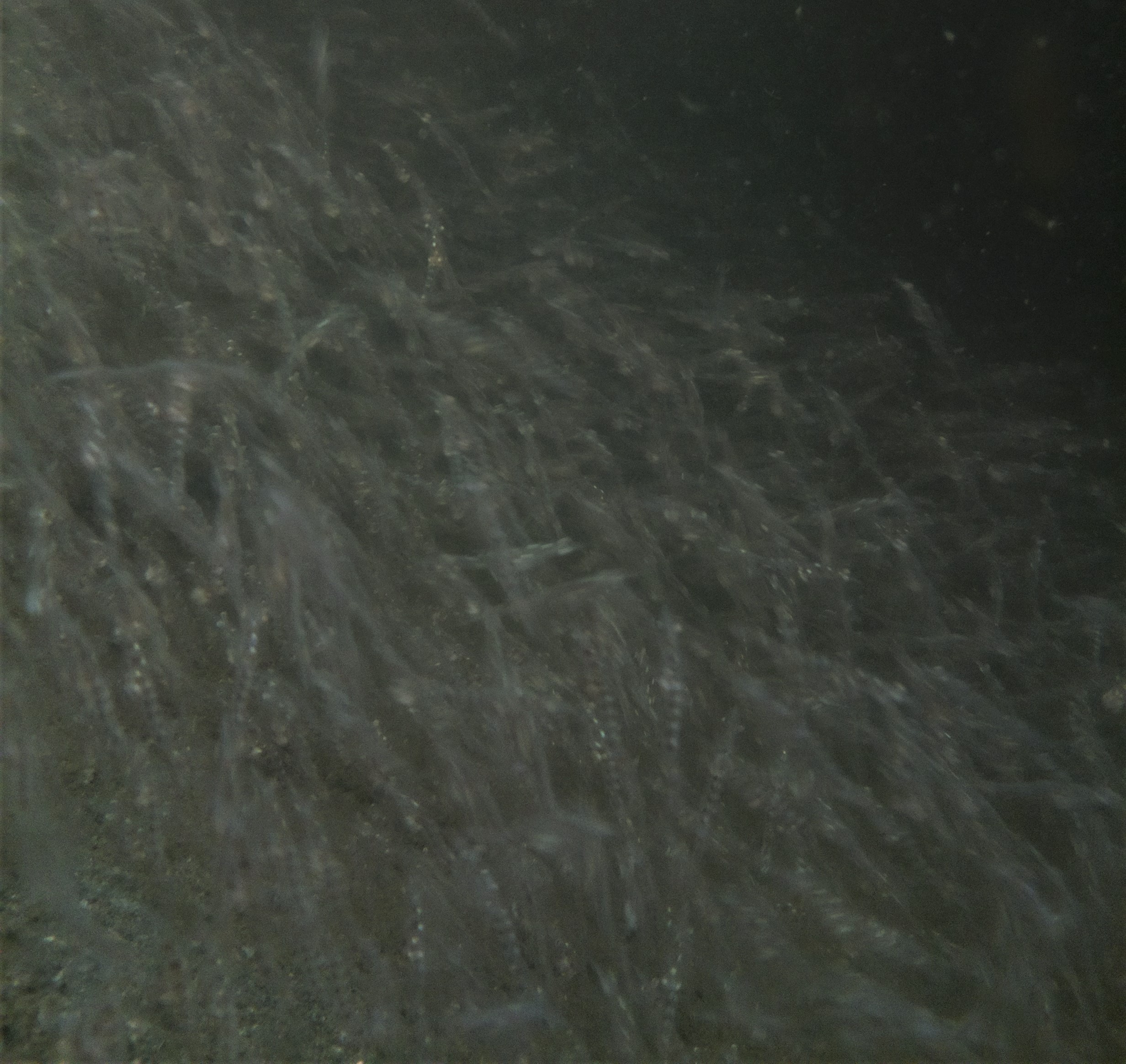
Swarming Mysid shrimp
![]()
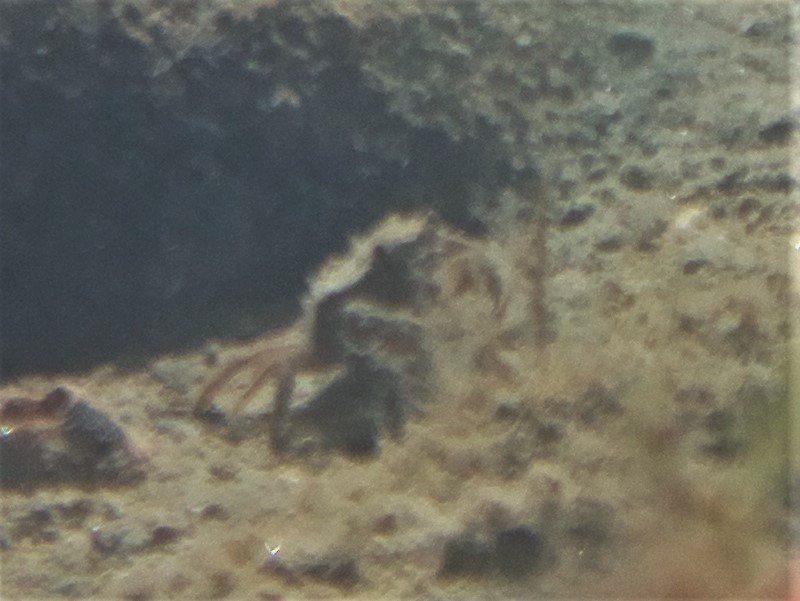
A little crab:
![]()
The results of this deployment has made me confident that all the current hardware performs as it should. The endurance is also very much with the spec of the project.
I believe that this specific version of the project is about one iteration away from being ready to be Beta tested.
More to come in the future.
-
Results: 4 days in the murky harbour
03/29/2021 at 17:59 • 0 commentsAfter some more tweaks I recently deployed the camera in the harbour and left it for 4 days. I removed all the images too dark to immediately see and applied some colour correction. (log about colours coming soon).
Deployment:
- ~4 days (dark photos removed)
- Interval: 4 min
- Location: Harbour, close to locks
- Depth: ~5m
Processing:
- Colour correction: correction script applied
- Frame rate: 5 FPS
- Number of photos: ~344
-
...More March results
03/08/2021 at 19:52 • 0 commentsA uneventful time-lapse of some mussels on the pillar of a pier.
Clearly visible mussel excretion. Night time edited out.
Interval: 2 min
Duration: 3 days
Depth: 30 cm
Number of frames: 380 -
State of the Project, March 2021
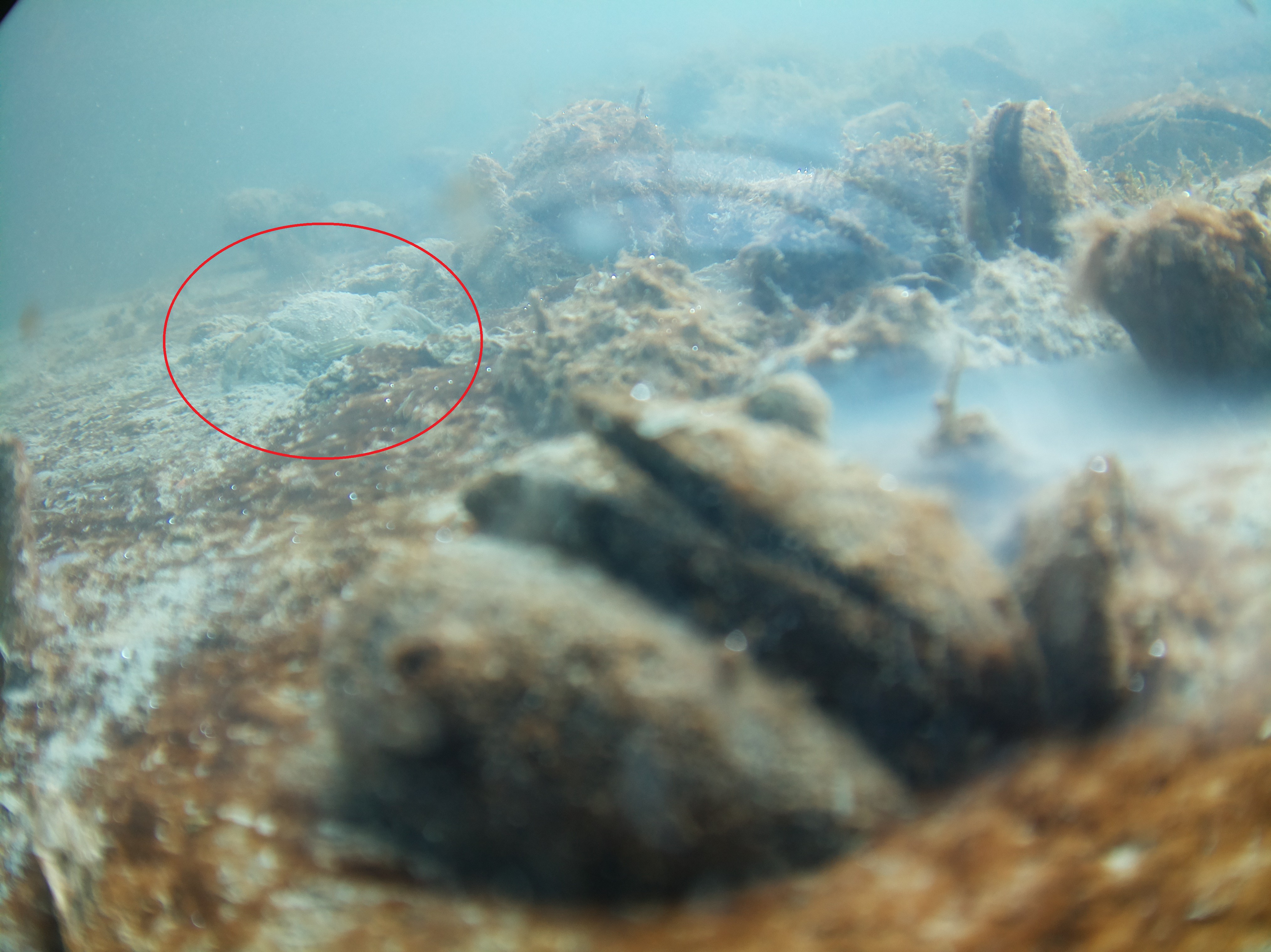
03/07/2021 at 13:41 • 2 commentsWe're back in the water for a new set of tests (finally)!
![]()
![]()
In the image above there are a few things to note, one: the nasty reflection caused by the transparent tube and internal mountings, BUT there is also critter, a small swimming crab passing the camera.
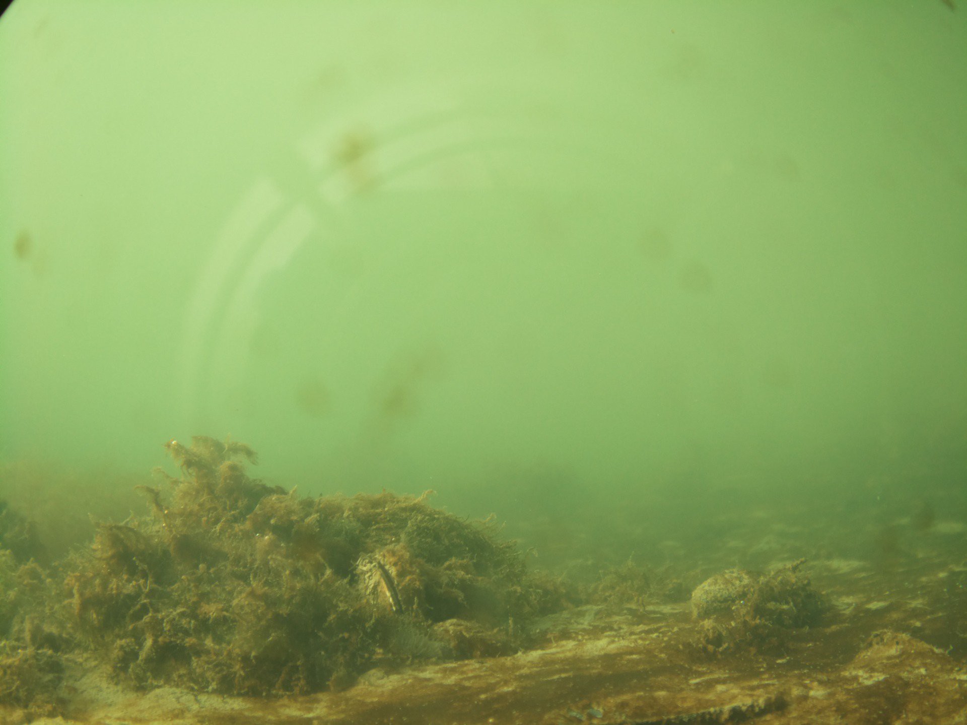
![]()
Another shot of a different angle, reflection visible, but a great showcase of the new HQ camera lens set to focus closer.
Here is a quick update on where I am at:
- I'm on the third iteration of a PCB, which was manufactured as V05.03 of the design. Code names Cod (alphabetical fish names for the versions that make it to production).
- PCB design is now two stacking PCBs, one with the MCU and some toys called the "Barnacle board" and the second, a carrier board for the pi, called the "Whale" or "Baleen board".
- PCB is now a larger rounder shape.
- The PVC tube, although bulky, is still the simplest and most reliable housing
- The camera has been upgraded to the Pi HQ camera which has been fantastic
- Current version has not been fully optimised as "low power" yet, but is the lowest power version so far.
- As I write this the camera is in the water for the second test deployment to try and iron out some more kinks. Yes, there are quite a few.
- User interface has been scrapped.
- LCD screen has been scrapped.
- Rotary encoder button has been scrapped.
- Project is still made with primary building blocks off the shelf, but the custom PCBs have some extra peripherals.
There are quite a few design choices to justify, which I will briefly go over here.
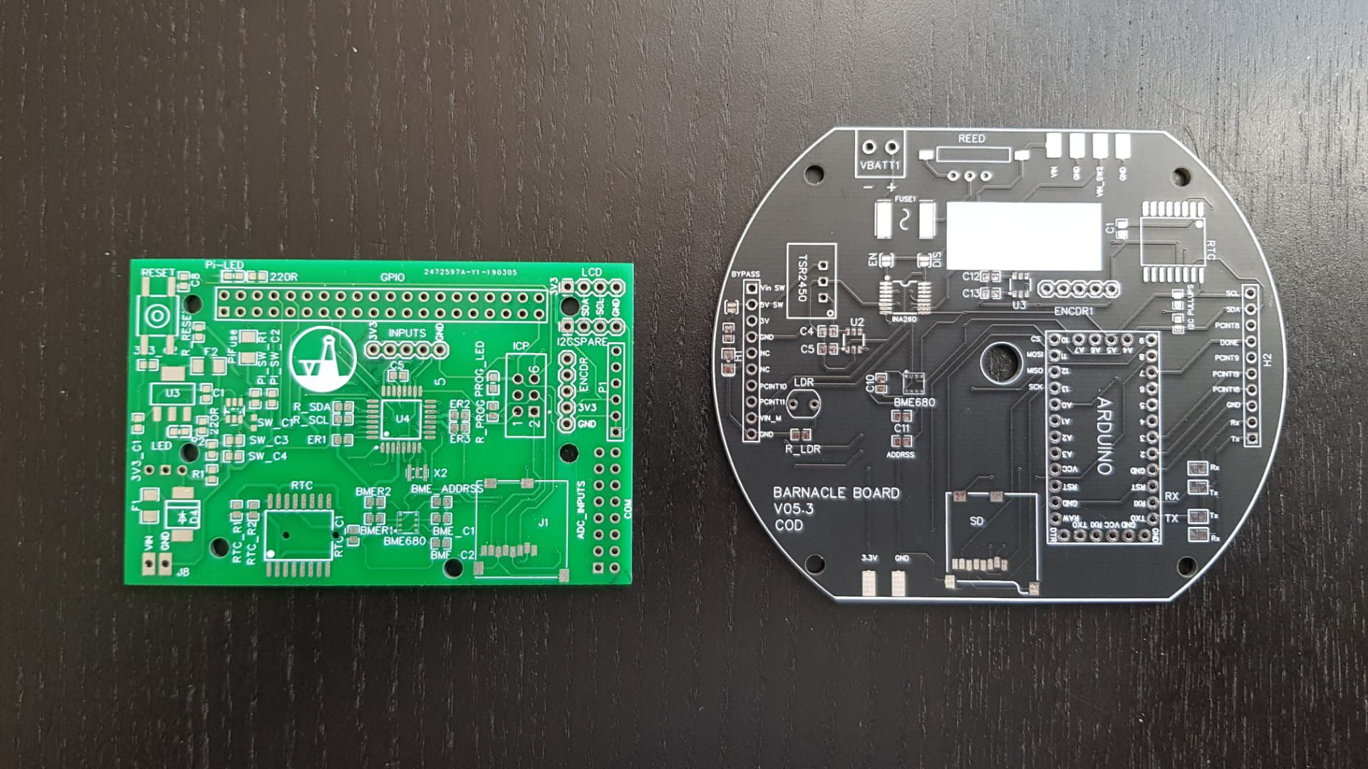
- PCB size. Below is a photo which compares the sizes in the "Ablacore" version (green, left) versus the latest "Cod" version (black, right). The Albacore was ambitious for my skill level at the time. I spent maybe weeks troubleshooting that board and there where many issues I found to be just too time consuming to fix. I found flashing a bootloader not to be trivial. I took a step back and decided that the space I have in the tube would allow for a bigger board, which makes the design easier to troubleshoot and the PCB shape was made to mound easier in the tube.
![]()
- Microcontrollers and the carrier board approach. To it's core, this project is a simple intervalometer. There are tonnes of amazing MCUs to use for something like this. I chose to stick with the ATMega328. Because troubleshooting and flashing over bootloaders was too time consuming at the time, I decided to move away from making a custom MCU board, and just going with a carrier board for an off-shelf arduino clone from Robotdyn. Lastly, frying or bricking an MCU does happen and discarding a pcb that was working perfectly otherwise is a pain for this prototyping phase.
- Stacking boards. The design changes between versions showed me the need to have some versatility in how the boards can be used and instead of planning for every change. The "Barnalcle" stacking on the "Baleen" has proven useful in the design process. Keeping the two parts of the circuit separate has made troubleshooting relatively easy. Plus it looks cool.
![]()
- Scrapping the UI. The Albacore version had a small screen to give users feedback to the mode and settings of the camera. This meant that a LOT of time was going into designing a control method that was intuitive yet still manageable on the firmware side. Although I enjoyed this, I felt that the amount of time it took to get it "just right" kept the project from getting wet.
- Power pack. Initially I decided that the I would go as simple as possible for the power pack for the project. A few iterations in, I decided that this was not good enough. I've used small lead acid batteries and off-the-shelf powerbanks, but found that the 18650 Li-ion battery tech was very mature and super accessible, which pushed me into building some really basic 18650 rechargeable packs. Also- turns out that I really enjoy power pack design. Just not so good at it.
I hope to add some more logs and explanations in the coming weeks as I do more tests.
-
Why the project stalled
11/26/2019 at 20:29 • 0 commentsI was at a very exciting point when I last worked on this project:
1. I was getting some cool results
2. I just took delivery of my first PCB for the project.
3. There was a lot of interest.
Then life happened ... HARD. I took a new job opportunity in a different country, uprooted my life, packed, sold my car, gave up rent and had to filter through my worldly possessions for what will make it into my two bags for my massive move. Many aspects of this project did not make it into the bags.
In the time it has taken for me to find my feet the project truly stalled. One big obstacle to getting started again is that I felt that the connection I had with the sea (and my neighbourhood kelp forest) has been lost. And in a big way I am still grieving that loss.
Without this turning into too big of a therapy session- I am now itching to get back in the saddle, but the pipecam as it is in the current vision may not be enough to explore the sea as it exists in my new home. Finding parts and materials in a new country with a different language has proven hugely difficult.
Time to rethink and reconsider my approach.
PipeCam: Low-Cost Autonomous Underwater Camera
Low cost autonomous underwater camera for long term deployments and exploration