Fred Fourie
-
An update.
09/10/2018 at 05:34 • 0 commentsI've been trying to do an honest update on the progress of the project. It's been slow going, but there has been LOADS of progress.
At the moment I'm in the trial and error phase of designing a controller board.
What the controller board does:
- Control
- UI
- Power management
I'm about a month away from getting back into the water. Of these three aspects, the user interface has taken most of the time.
UI
This has been taking most of my time. If you can avoid it.
How users interact with a device is a massive study on its own. I've been juggling giving the users many control options while keeping it as intuitive as possible. This has taken many iterations and hardware changes. It's hard to draw the line between what's possible and what's practical. I think I've finally struck an acceptable balance in practicality/functionality. At the moment users can set up the device with a dial and a tiny screen for feedback.
Control
The PCB design & etching process is quite rewarding, but it has been a bit of a slow slog. I've made many mistakes in the designs and I'm close to creating a 4th iteration of the board which will hopefully be the last version before I start adding some extras. The design also keeps changing as I learn more about more suitable parts.
Power
Power management has been a real eye-opener. There is a lot of control I need to add to reduce the overall power consumption of the project. The power banks I've been so excited about has proven to have some real limitations. This is worth a log in the future, but I've basically decided to scrap them. In short, they are too smart for their own good.
I've also come to the conclusion that the project is at a cross-roads. I see this splitting off into two branches. One being the quick and easy one, that folks can build on the cheap and get in the water fast (with some limitations). Hopefully I'll finish a how-to guide for this in the next few weeks.
-
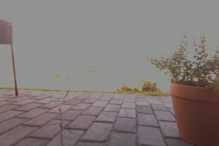
Feeding Time at the Research Aquarium: Timelapse from Video
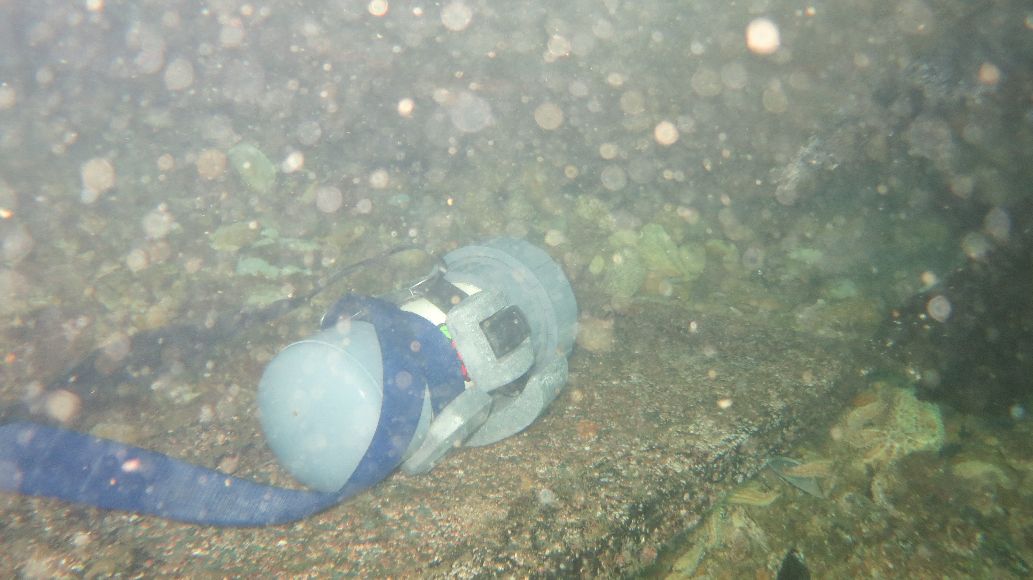
06/04/2018 at 05:24 • 0 commentsI recently got a chance to drop the project in a tank filled with West Coast rock Lobster at the local research aquarium during feeding time. The camera was set to do 15min videos overnight.
Here is a timelapse made from the first 15min of footage:
Problems encountered:
- Low light (nothing I can do about that at this stage)
- Camera did not switch over to next flash drive after current one was full
- Focus was set too far forward to catch all the chaos right in front of it
-
Two drops: Time-lapse vs Video
04/25/2018 at 05:50 • 0 commentsWhile I'm still busy with the low power electronics, I'm trying to use the camera to get a feel for the capabilities and limitations... and to figure out how to make it user friendly.
So over the last weekend I did two ~5hour drops, both from about 10:00 to 15:00 for the best lighting.
The first was a 30sec interval time-lapse at the entrance of a small cave.
- Depth: ~2.5m
- Mode: Photo
- Interval: 30sec
- Exposure: 'Beach'
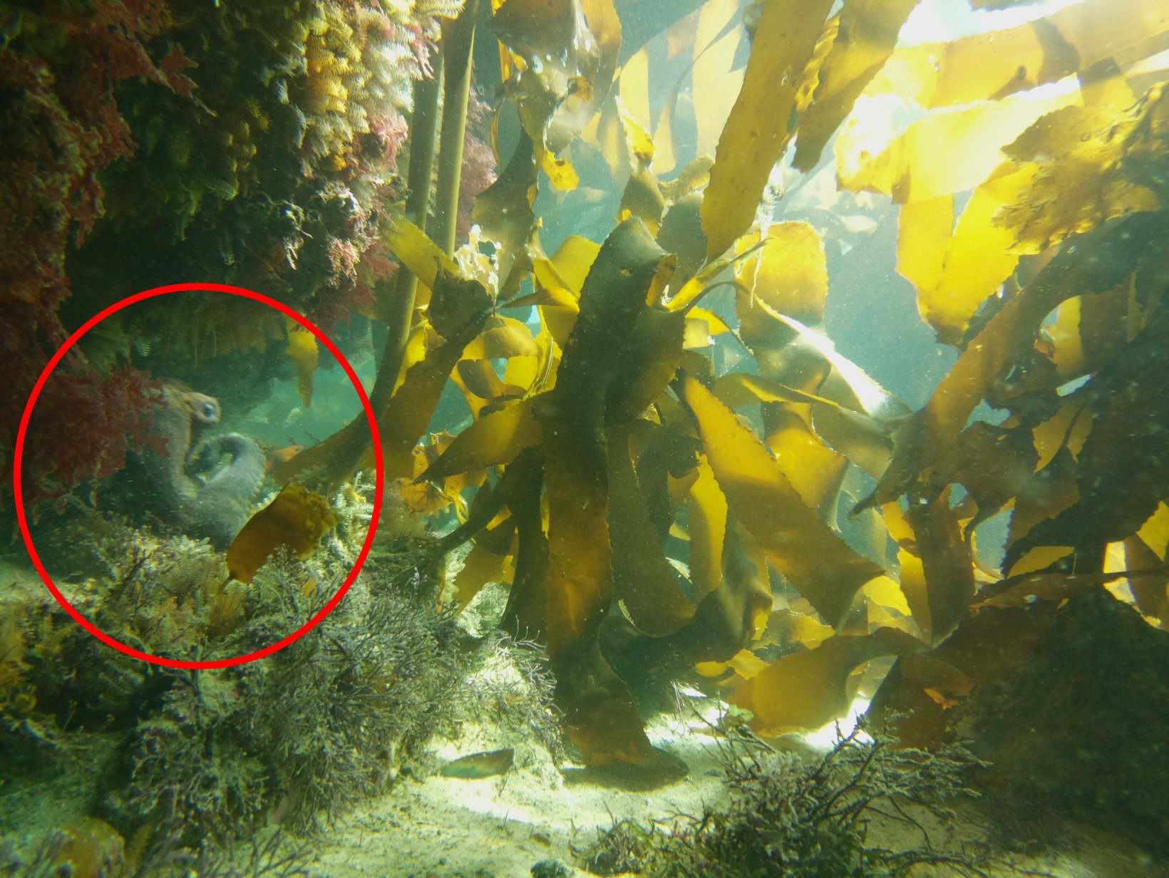
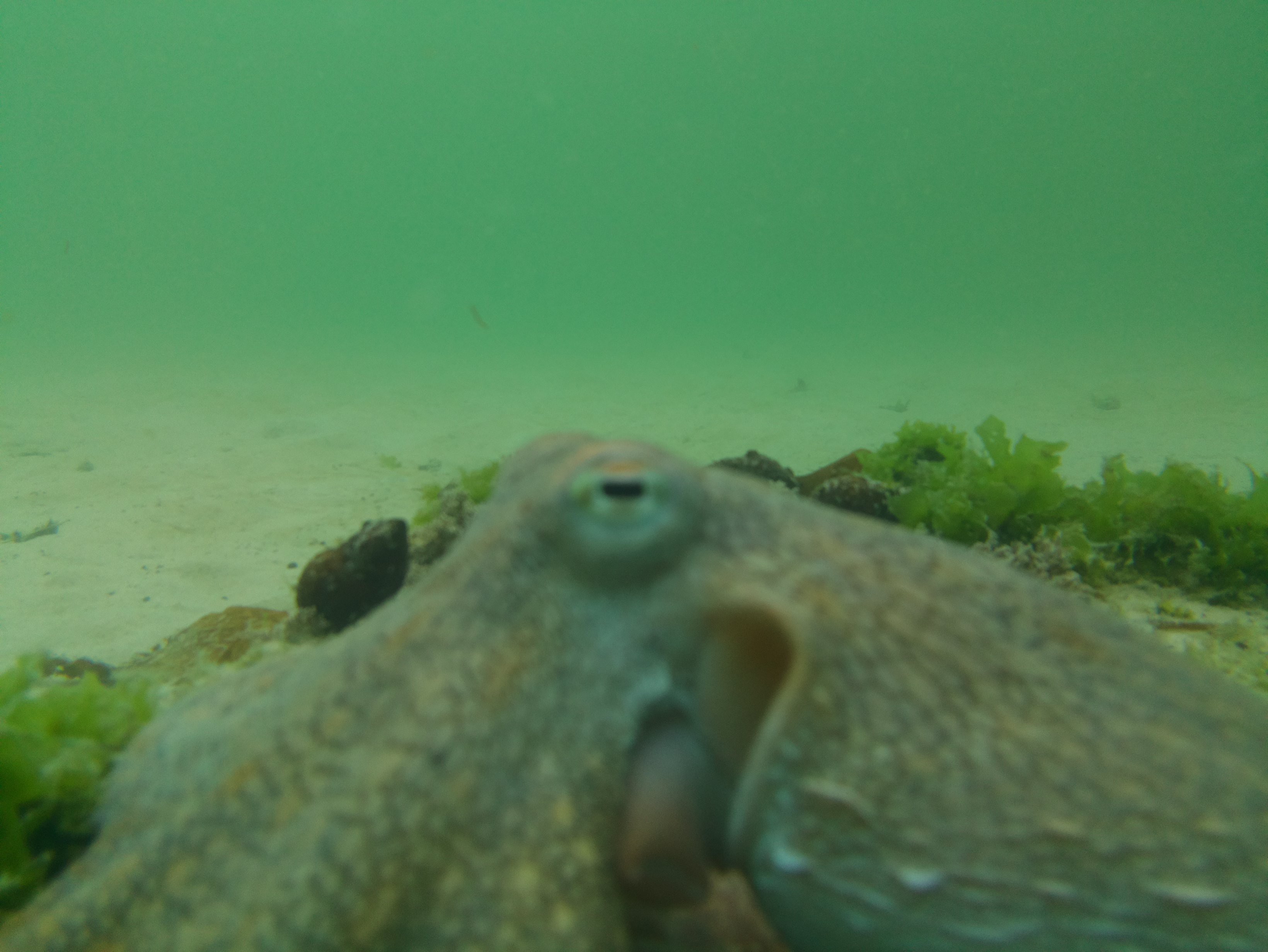
About two hours into the deployment, an octopus discovers the camera, fiddles with it and points it into the cave. Which is both delightful and frustrating. The time-lapse misses most of the action. The pipecamera does not deal with low light conditions that well at this stage :\
In case you missed it, here is the culprit:
![]()
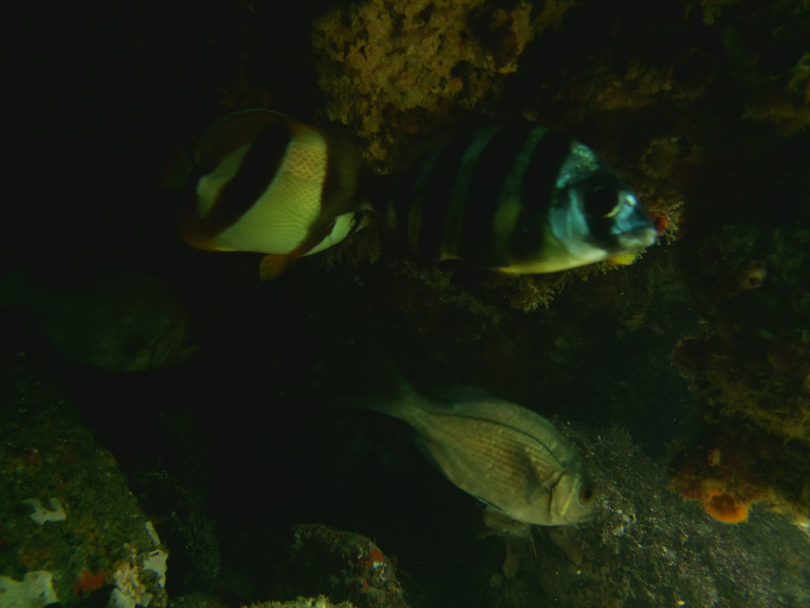
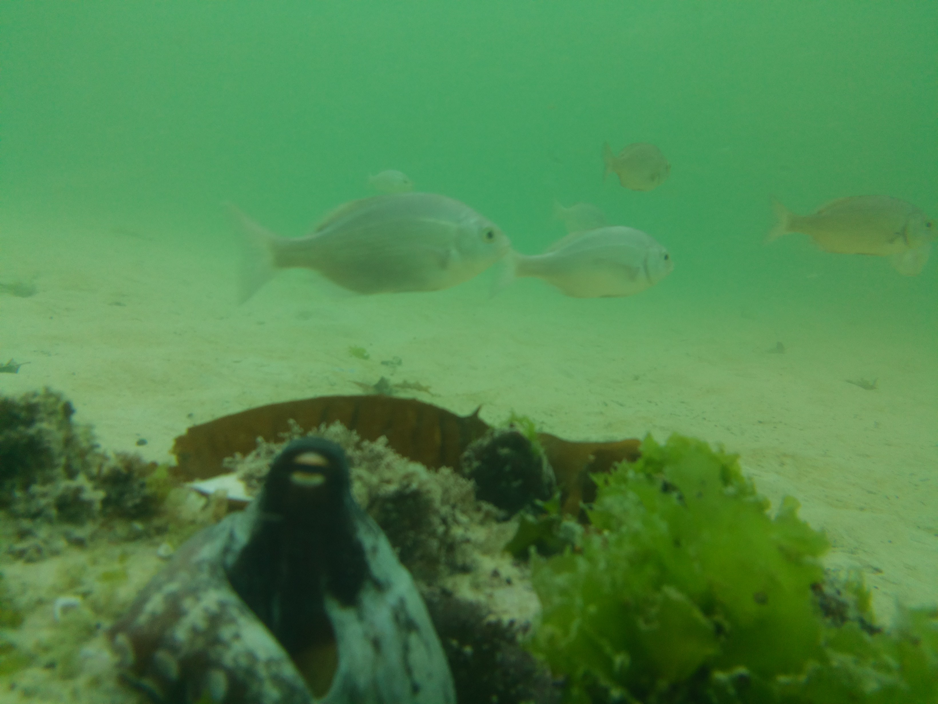
The rest of the photos taken are very dark, fortunately there are some interesting fish hiding in the cave, but it's too dark to do a time-lapse of these photos. I will consider rather setting the exposure to 'auto' in the future to deal with such... interferances.![]()
The second deployment was done from 10:30 - 15:30.
- Depth: ~1.5m
- Mode: Video
- Video lenght: 15min
- Interval: 15min
- Exposure: Auto
Because I missed so much action in the time-lapse the day before, I decided to just go with continuous video.
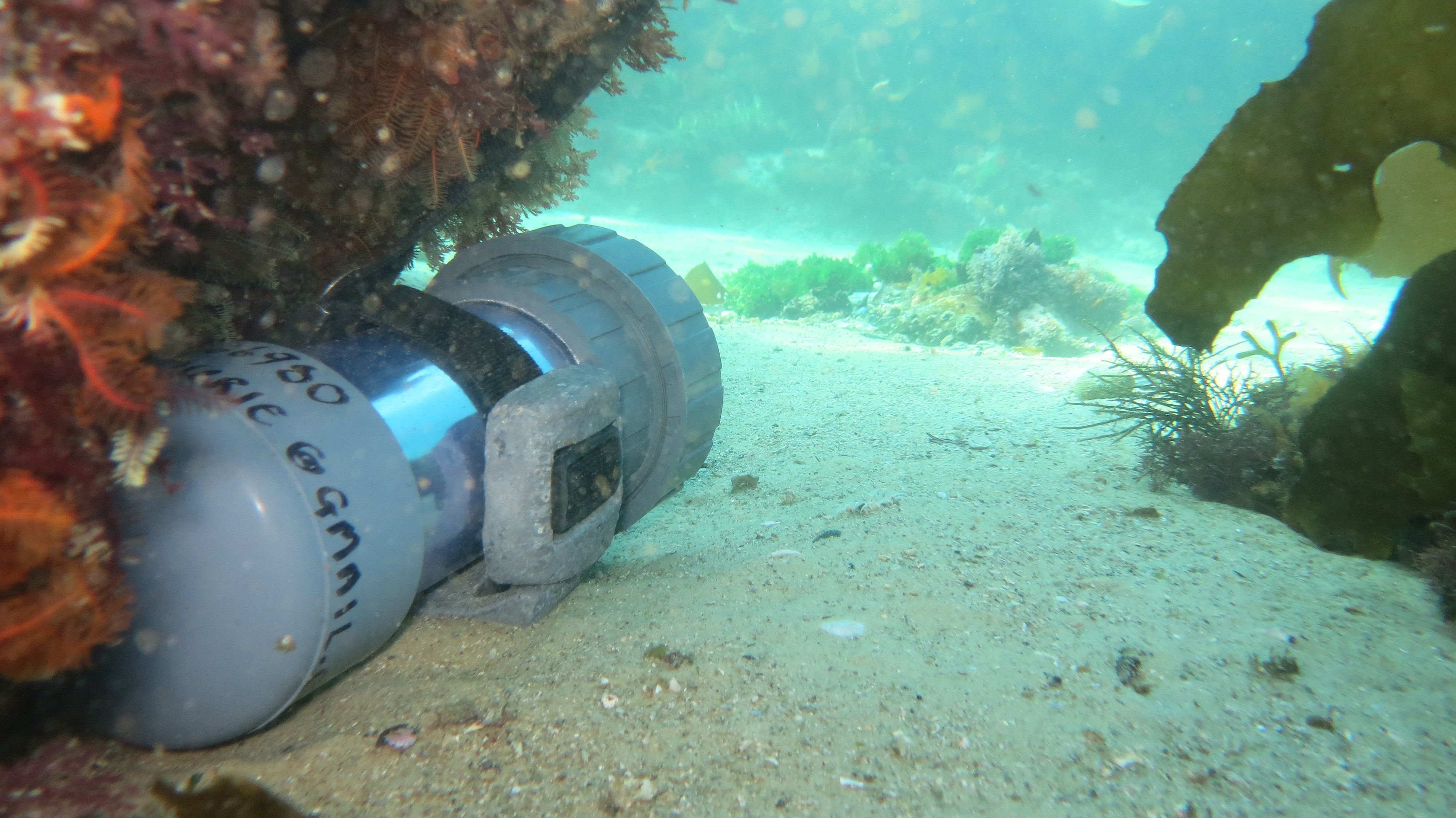
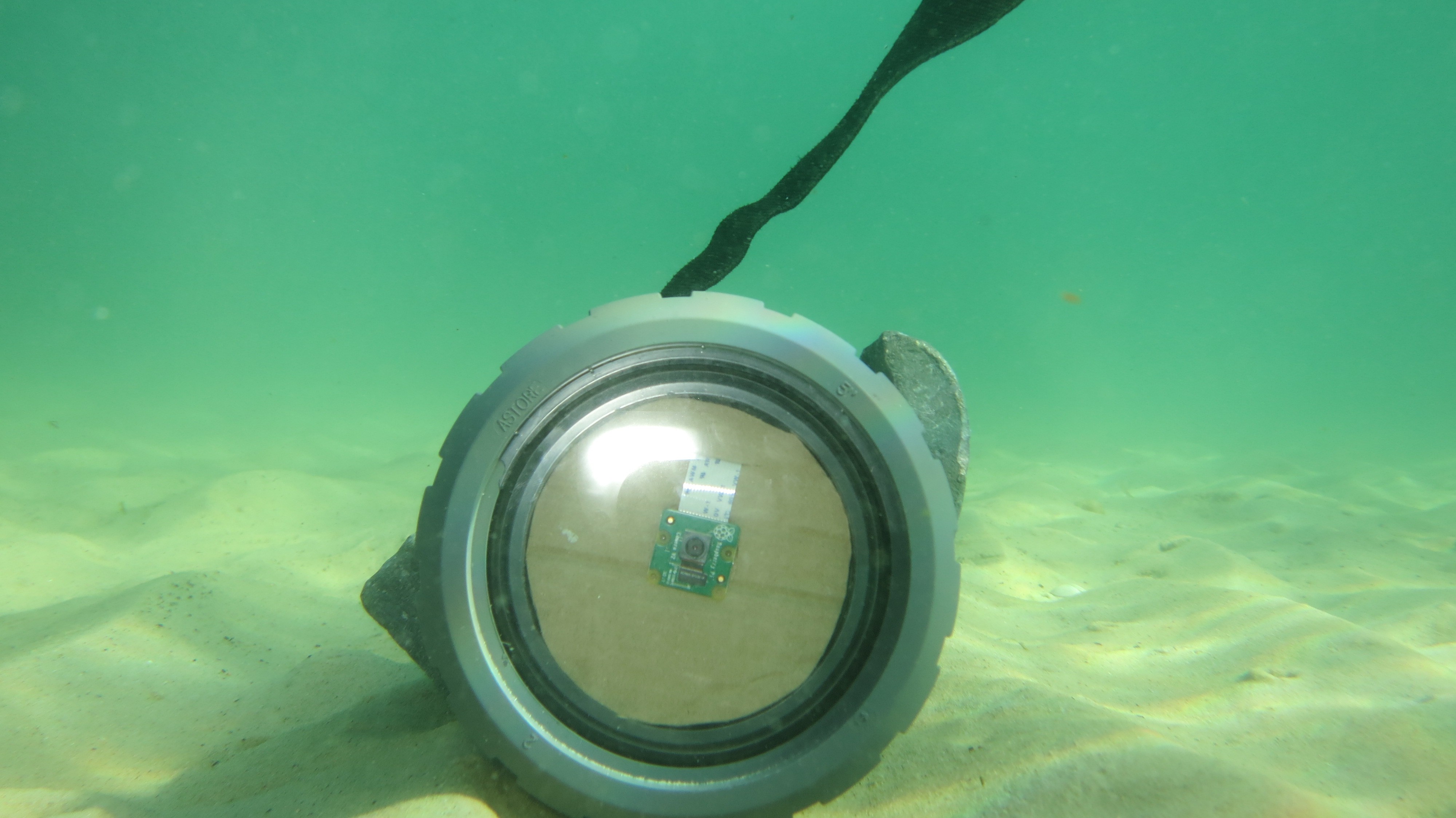
I placed the camera under a small overhang looking out to a small rocky outcrop. The camera eventually shifts in the surge, which is the reason for the skew video later on. I will need to look into adding a bit more weight in the future.
![]()
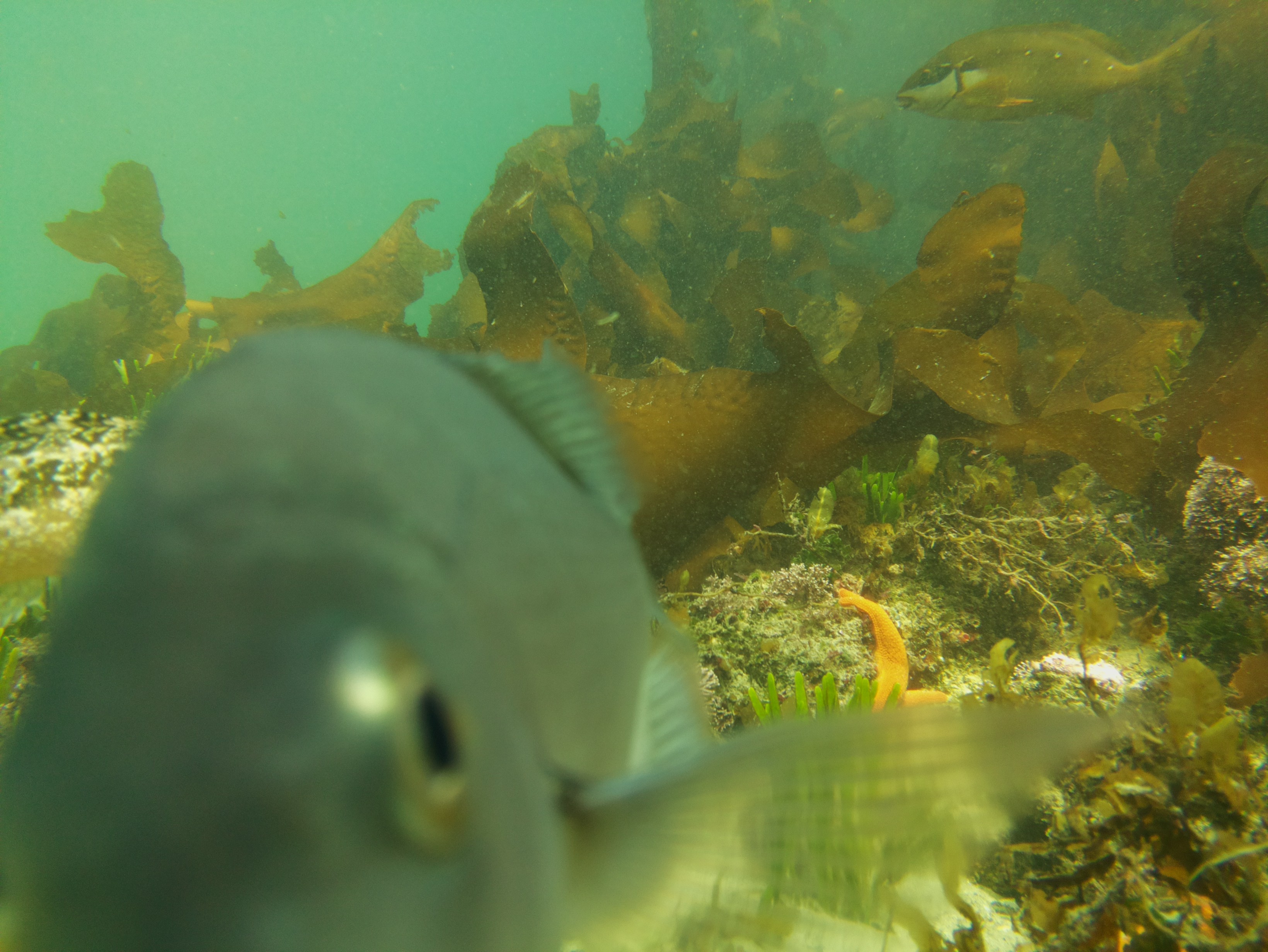
At first I thought the footage was pretty boring, but the problem with having 5 hours of footage is that you just skip through it, often missing some of the fun stuff that are only a few seconds long. The little outcrop actually got quite a few visitors.
After a second round of looking at the results (on recommendation from my video journalist wife), here are some of the highlights:
A school of fish visiting the deployment:
A cuttlefish hunting past the frame (LOVE IT):
Below I took a about a 10min snippet over two videos and converted it into a time-lapse. This is the kind of footage I'm interested in getting more of:
-
Risking the first overnighter
04/03/2018 at 05:24 • 0 commentsHere is some results and comments on the first overnight deployment.
![]()
Details and findings:
- 1 minute interval time-lapse was set
- Pipecam was rested on a small reef on the edge of a kelp forest .
- ~2m depth
- Resting with a 3kg weight belt
- Cronjob set up to operate only between day light hours which is roughly 07:00 - 19:00 at the moment, which looks like this:
* 7-19 * * * script.py >> output.txt - Was recovered with no damage or leaks
- The pipecam ran for about 25 hours before running out of power.
- The timezone of the pi was not the same as the cron, leading to a 2hour discrepancy
- About 2.7 Gb of photos was recorded, which in this case was about 660 photos
- At least two groups of divers found the camera at the location
- Fish are very interested for about the first hour of deployment
And here is a video of the results:
Some conclusions:- Needs better identification signage for passing divers
- Add STATUS Led to easily see that the project is still alive
- Check timezone and sunrise/sunset times with pi timezone
- Project is way more power hungry than anticipated (probably the USB hub adding more power than expected)
- Kelp forests are pretty, but they make for VERY busy time lapses and is better suited for video
- A night time deep sleep will score another ~12 hours on the current setup
Now for some bench tests before we put it in the water again.
-
Hammer time...
03/26/2018 at 08:14 • 0 commentsDylan and I completed a rush V1.5 as described in the previous log.
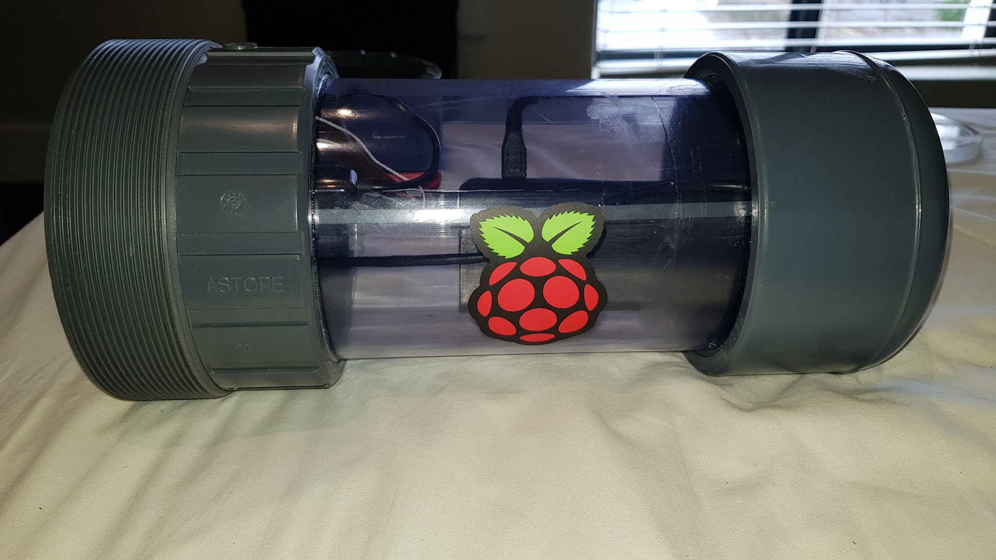
The new version sports a flashy transparent housing, but is essentially still the same concept with upgraded parts.
![]()
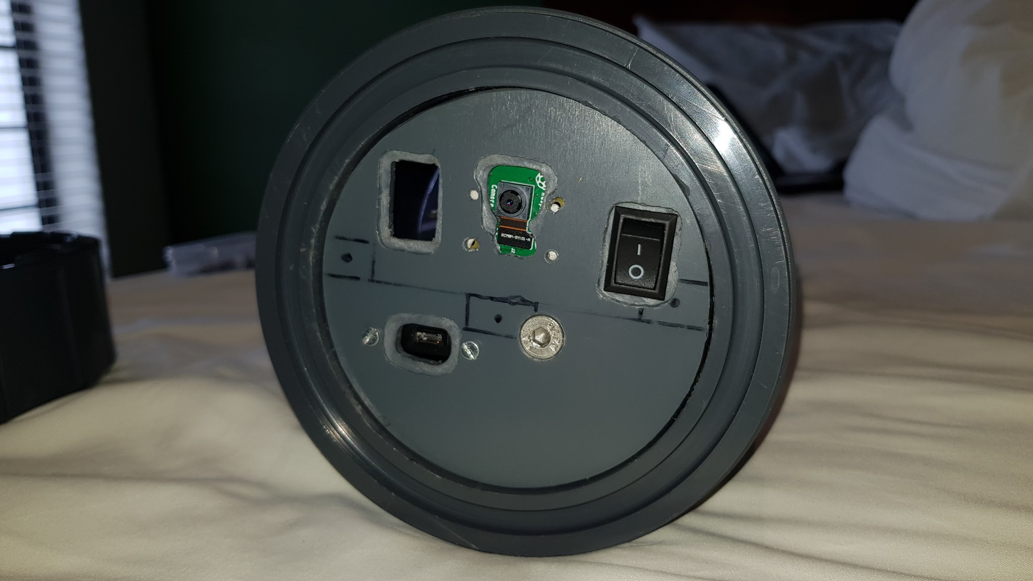
The internal mounting has also been changed so that the on/off switch and recharge port is accessible by only removing the lens.
![]()
The next phase of the project is just to hammer it: Test it as much as possible, tweak settings, refine user interaction and push the housing to see what it's actual limits in the water are. We will construct a second camera to test this phase. One of my continuing questions is whether we need to do video or time-lapse: The short answer is "it depends"
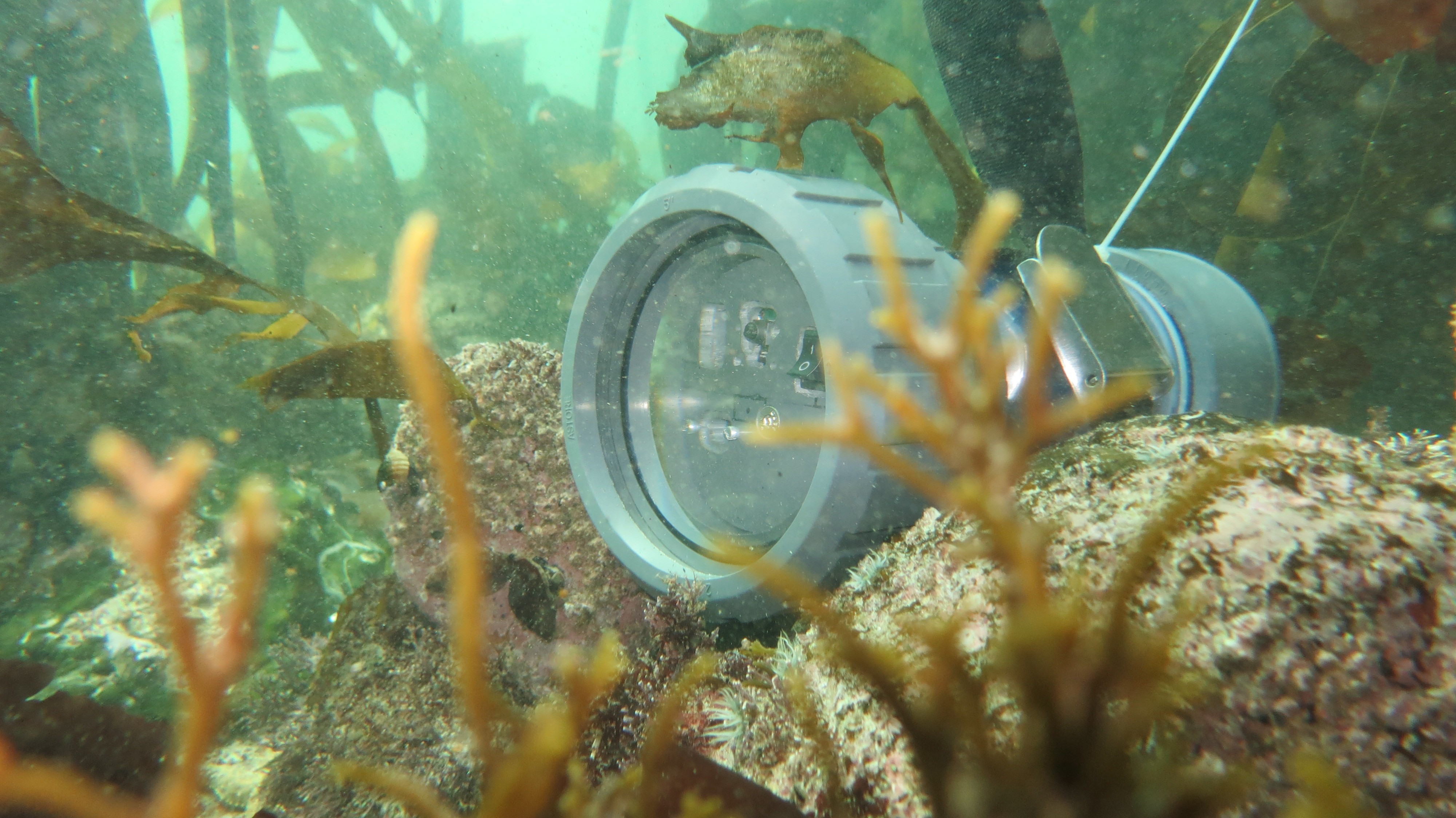
As an intro in this phase I dropped the pipecam into a local kelp forest for a bit to test the new video modes (Take ~15min videos very 15mins).
![]()
A short clip from the results of this test:
![]()
Next test is hopefully a week deployment in a marina?
-
Modifications after some tests
03/10/2018 at 18:09 • 0 commentsFour main things have become clear from the first set of tests.
![]()
1. Power will need to be increase/managed
The sealed lead acid battery is a cheap but bulky solution. The 12V 2.4Ah battery costs about R130. I have the space to easily double up on that battery, so that gives me 12V ~4.8Ah for about R260. BUT I can get a power bank with a similar form factor at 5V with 10 Ah of capacity at a prices of ~R270 PLUS I don't need the DC regulator board. So it's a bit of a no-brainer. I'll be swapping over to a lithium ion power bank.
![]()
I have also decided to change from the Raspberry Pi 3, to the Pi Zero W to clamp down on the overhead. This means a loss of 4xUSB slots, which I will need to recover with an external USB hub which may mean a little bit of a extra power penalty.
2. Storage space needs to be increased
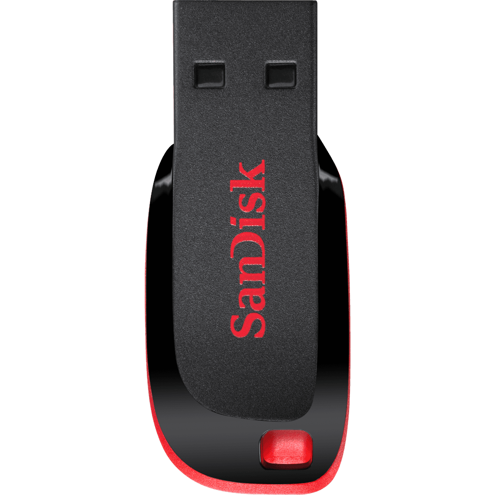
Good video chows space. No way around it. I need to beef up my storage capacity to match the battery endurance. Time-lapse operations are a lot easier on storage, but video needs to be of good to maximum quality to make it worth it. My preference so far is the SanDisk Cruzer Blade flash drives, because of the small size and ease with which it can be removed from the Raspberry Pi after operations. I also like that they come in way-out colours, which make them easy to ID.
![]()
3. Housing need further tests
A minor/slow leak was found on the housing during the second test. Luckily the internals were protected by the internal mounting which lifts the electronics off the bottom. I have my suspicions on what is causing the leak.
I handed over the housing over to Dylan (the mechanical wiz and partner in the project) for testing and he will be building the a new housing while I focus on some software and electronics.
![]()
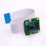
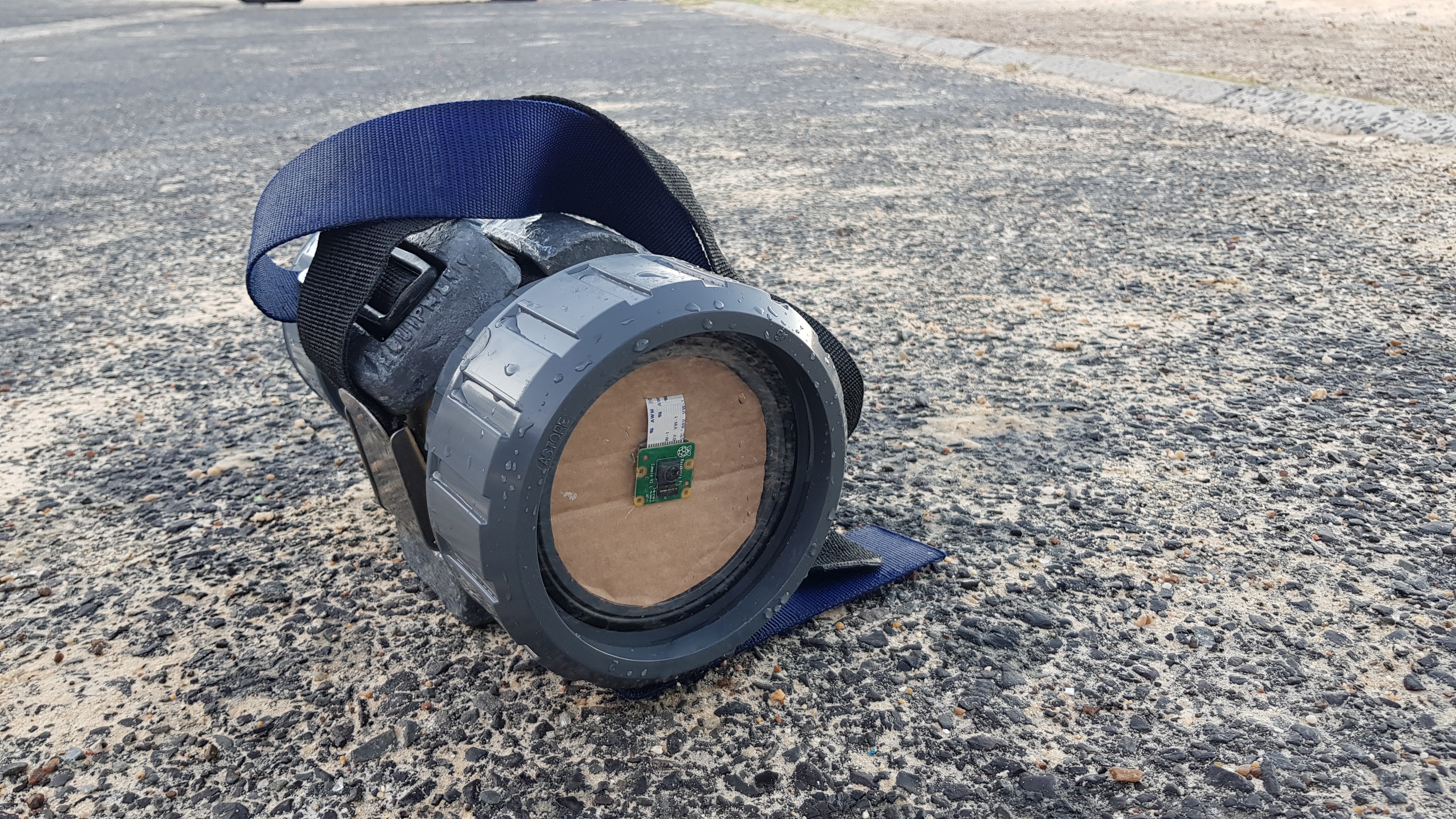
4. The Raspberry Pi V2 module is NOT robust
Part of the reason why I'll be looking at the electronics: Looks like I fried a V2 camera module, even after taking care to handle it as little as possible. I will need to look into having a case 3D printed. The board itself is notoriously prone to static and has a rather fiddly ribbon cable. The board sports a crypto-chip to discourage cheap clones, which I can forgive to an extent. Still- for ~R400 it is still hard to beat. It's strike one for the module. I've had to order a new module, hopefully I can refine my design so that there is even less interaction with the board and it can prove that it's still the best choice for the project.
![]()
-
Results!
02/27/2018 at 05:37 • 0 commentsFor the first water test I've set the camera to 2 photos per minute and deployed it for about an 1 hour in ~2m of water (at a beach close by). Where I tested the camera there are LOTS of octopus, so they made for good subjects.
The small 2.4Ah lead acid battery can do around ~5 hours with the current configuration.
![]()
![]()
Being impatient I moved the camera around a few times, but this turned out to be good for the tests.
Below are some of the results:
![]()
![]()
![]()
And here is a time lapse:
![]()
Notes and issues:
- Resolution: 2 photos per minute is not fine scale enough. I was hovering a couple of feet away and there was two octopus fighting over the hiding hole. Footage missed that completely.
- Focus: I will need to determine where the best range of focus is for the camera. In this case I missed it.
- Light: The Raspberry Pi V2 handled they underwater lighting REALLY well. Or shall I say a lot better than what I thought.
- Ballasting: To keep it in place, two weight belts were used. +4kgs of weight was put on.
- Feedback: Consider a ON light. Note LED lights will have an effect on animals. So might not be worth it.
Moving forward (the immediate future).
Do another test:
- Test video. Test power consumption with video.
- Find ideal range for the focus.
-
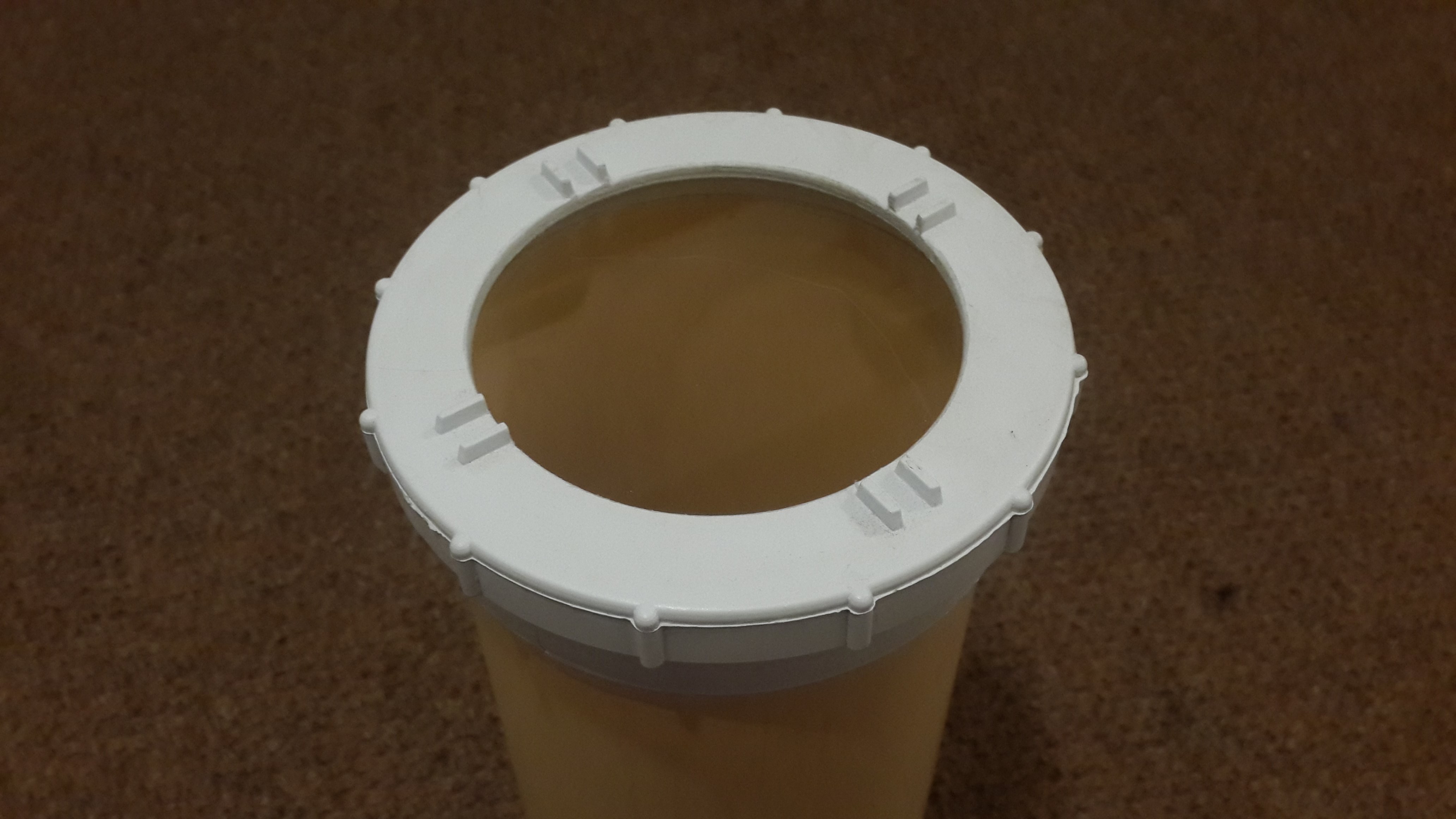
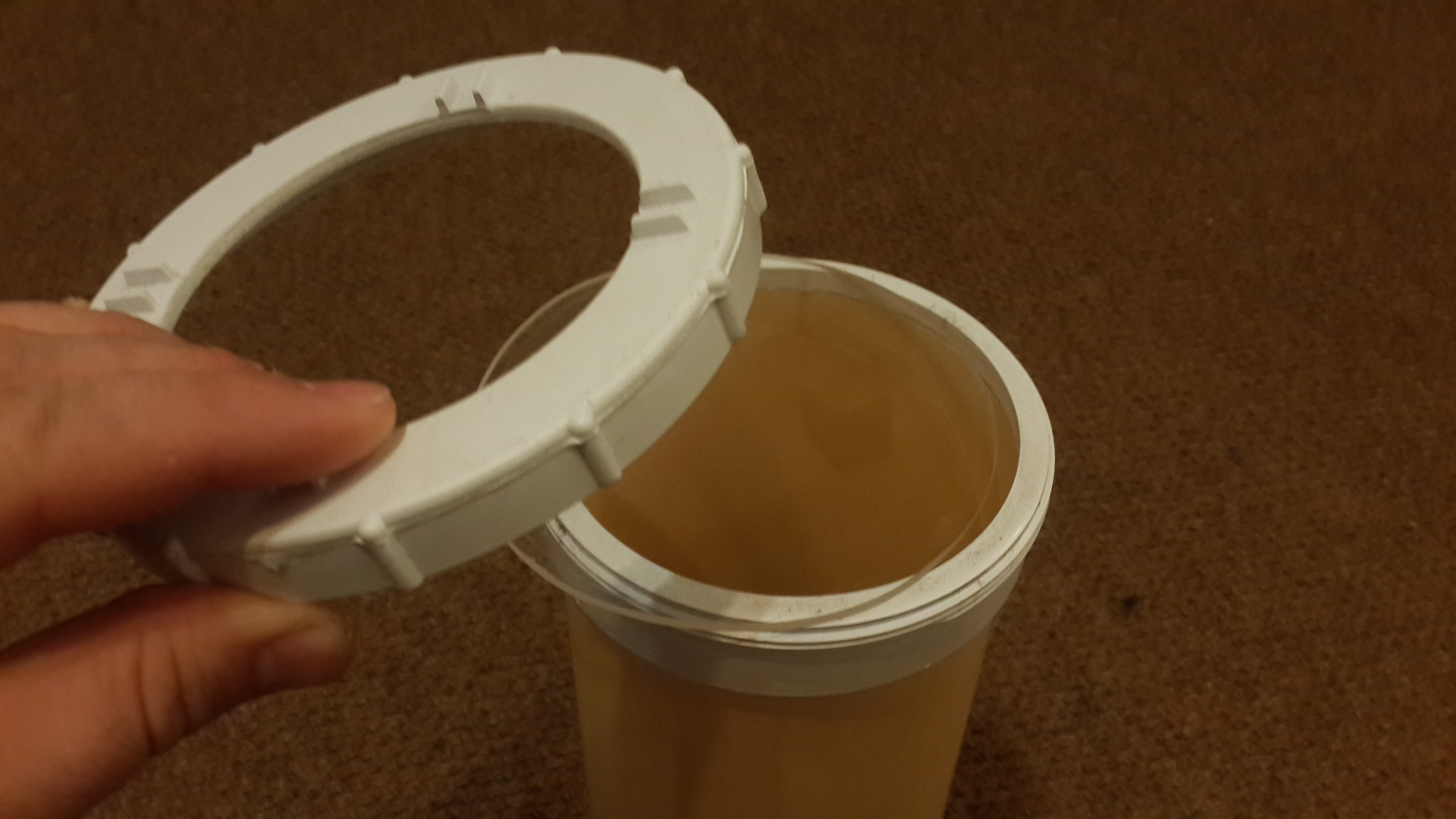
Housing V1.0: a New Hope
02/24/2018 at 17:03 • 0 commentsThere has been considerable progress in this project. This is mainly because I have been asking for help (who knew).
![]()
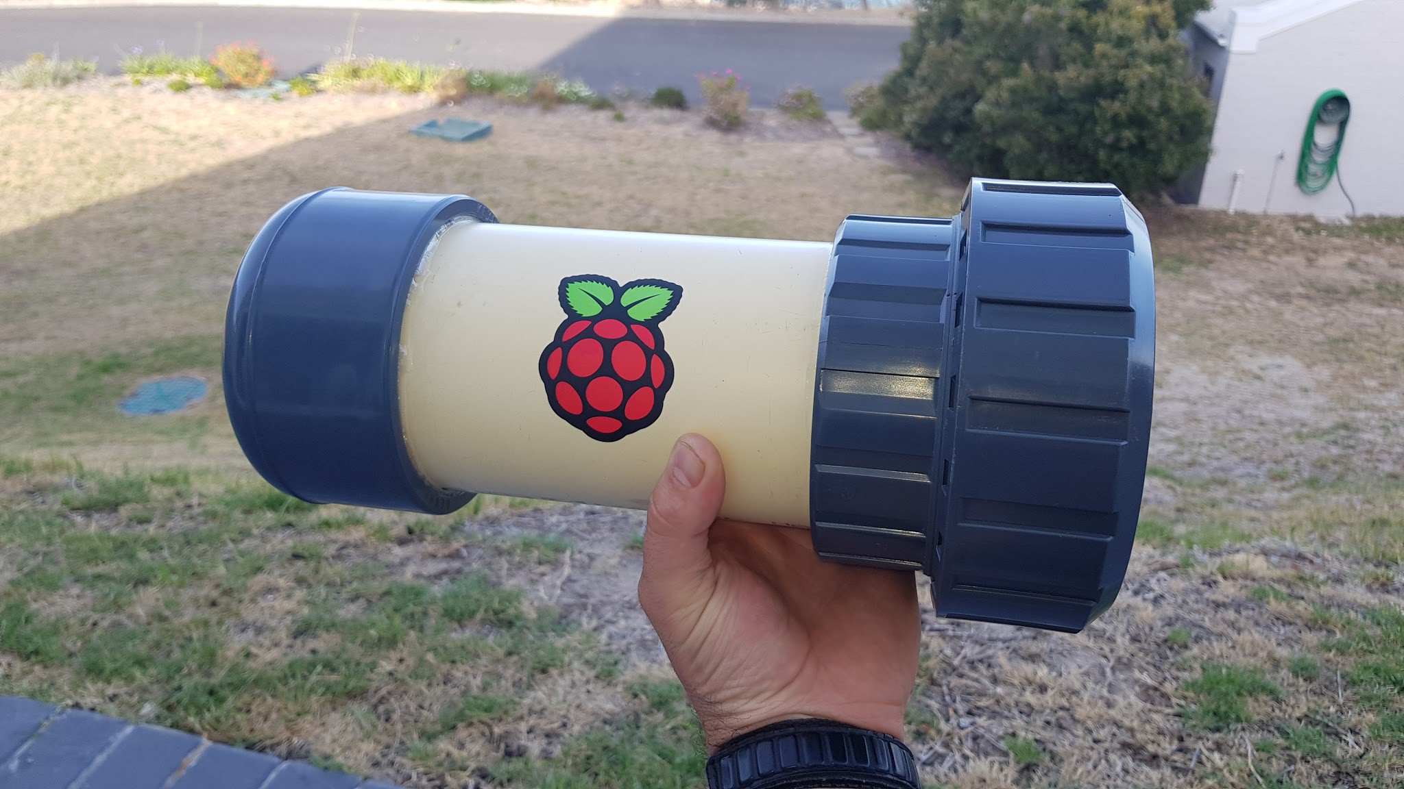
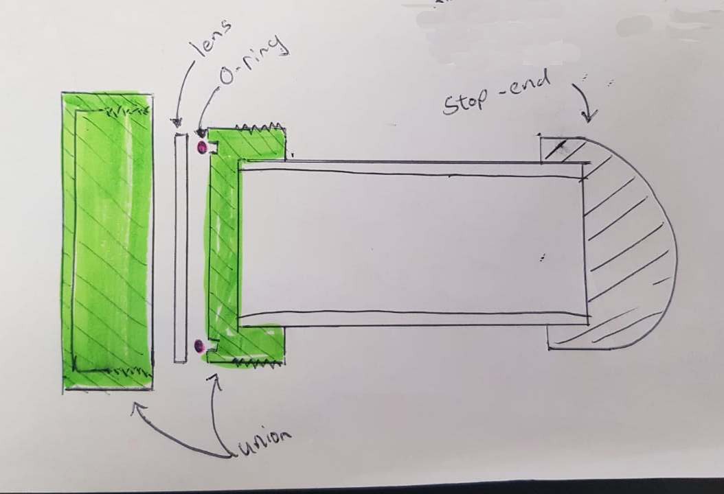
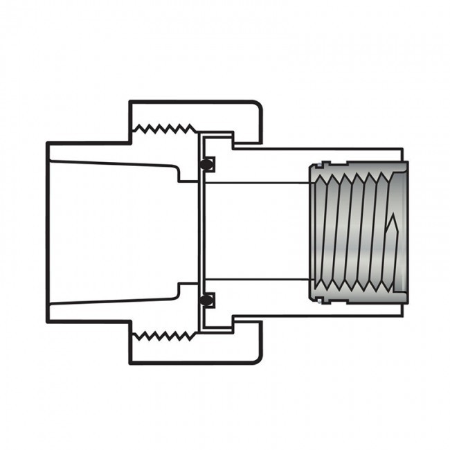
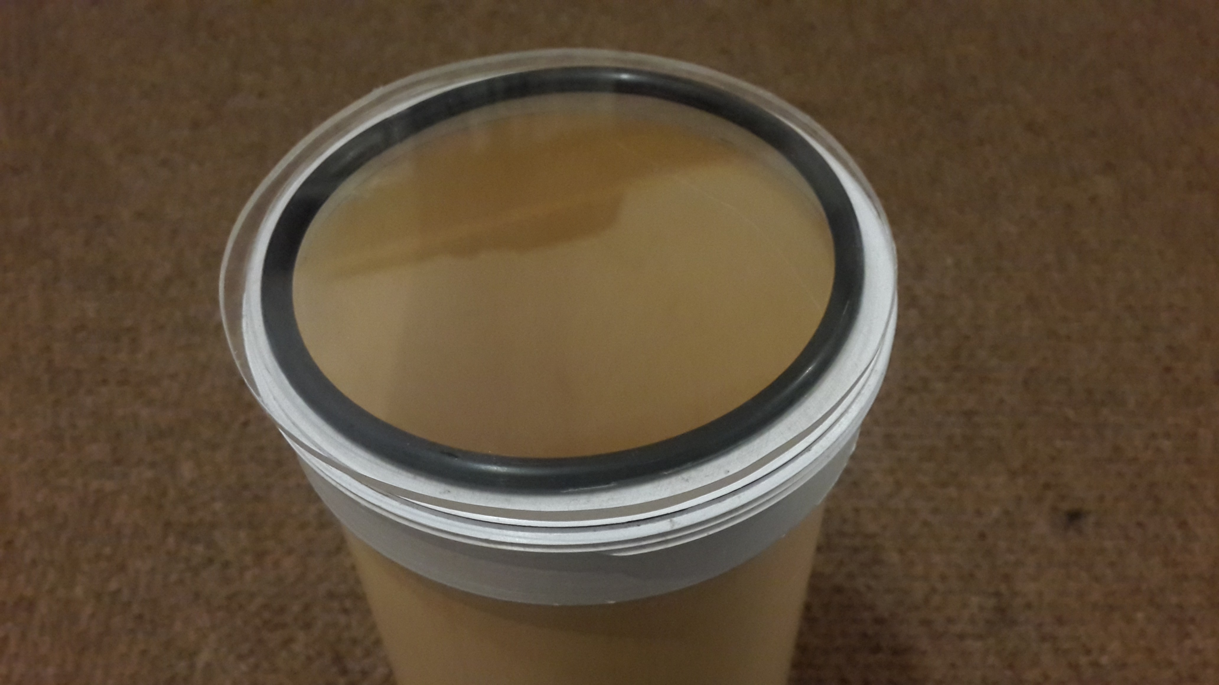
The new housing allows for a great seal and easy access to the electronics. The key to the progress has been the PVC union used to hold the lens and letting go of the tethered idea.
![]()
![]()
The pipe used is still the 110mm waste pipe, but the new heavy duty fittings has given me the confidence that this project will perform the way mechanically as I hoped.
Summary of what has changed since the last log
- Now using a Pi3 instead of a Pi2
- Camera module is now the PiCam v2
- Raspberry Pi sticker on the tube- totally worth the R15
- Real Time Clock added to keep time for timelapse intervals
- Unit is now self contained and runs off a battery (making a gland brings up issues)
- Lens is now 10mm perspex
- Voltage regulator is now a proper DC-DC adjustable Voltage regulator module
- ON/OFF switch
![]()
The parts (costs in South African Rands)
- 110mm Waste pipe (ordering 1m transparent PVC 110mm pipe at a specialist plastics place costs about R300)
- 110mm PVC Female stop end (CA1) (costs about R50)
- 110mm PVC union (comes with an oring groove and oring) (costs about R160)
- 10mm Perspex lens (costs about R80)
- Raspberry Pi3
- Raspberry Pi camera module V2
- 12V, 2.4 Ah Rechargable sealed lead acid battery
- Adjustable Dc-Dc voltage regulator
- DS1307 RTC module
- ON/OFF switch
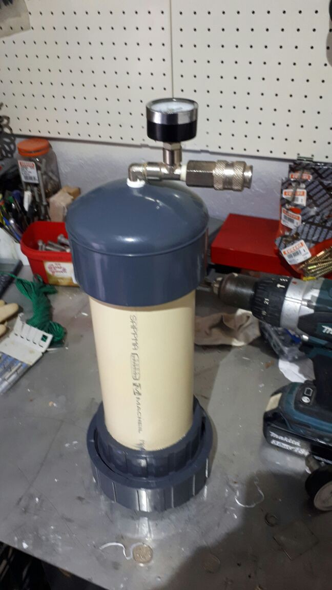
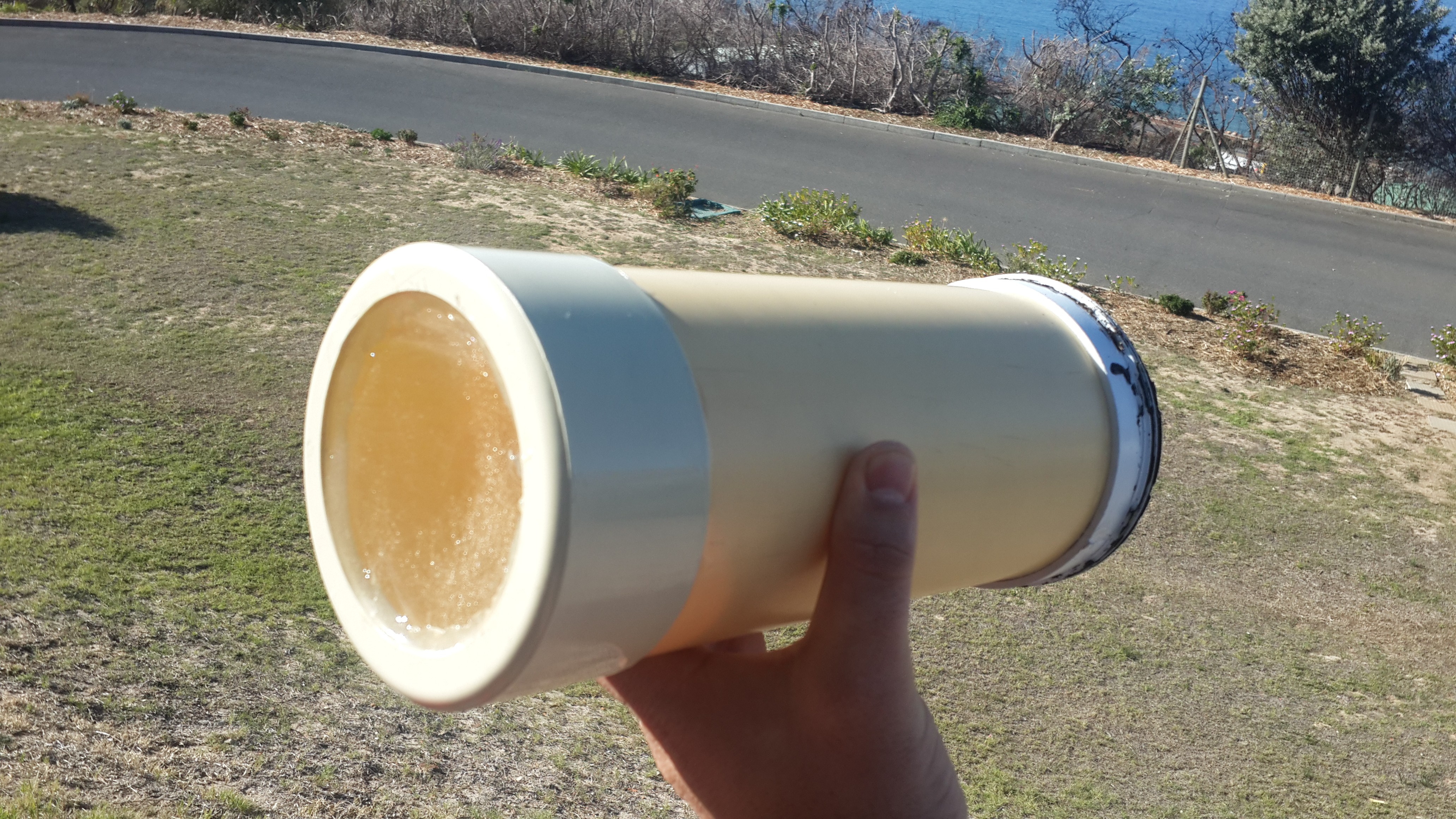
Testing
I approached a friend for help. I gave him the housing and within and hour he had it rigged up and was pressure testing the housing.
![]()
![]()
These tests revealed a few things:
1. The housing- as is does not leak.
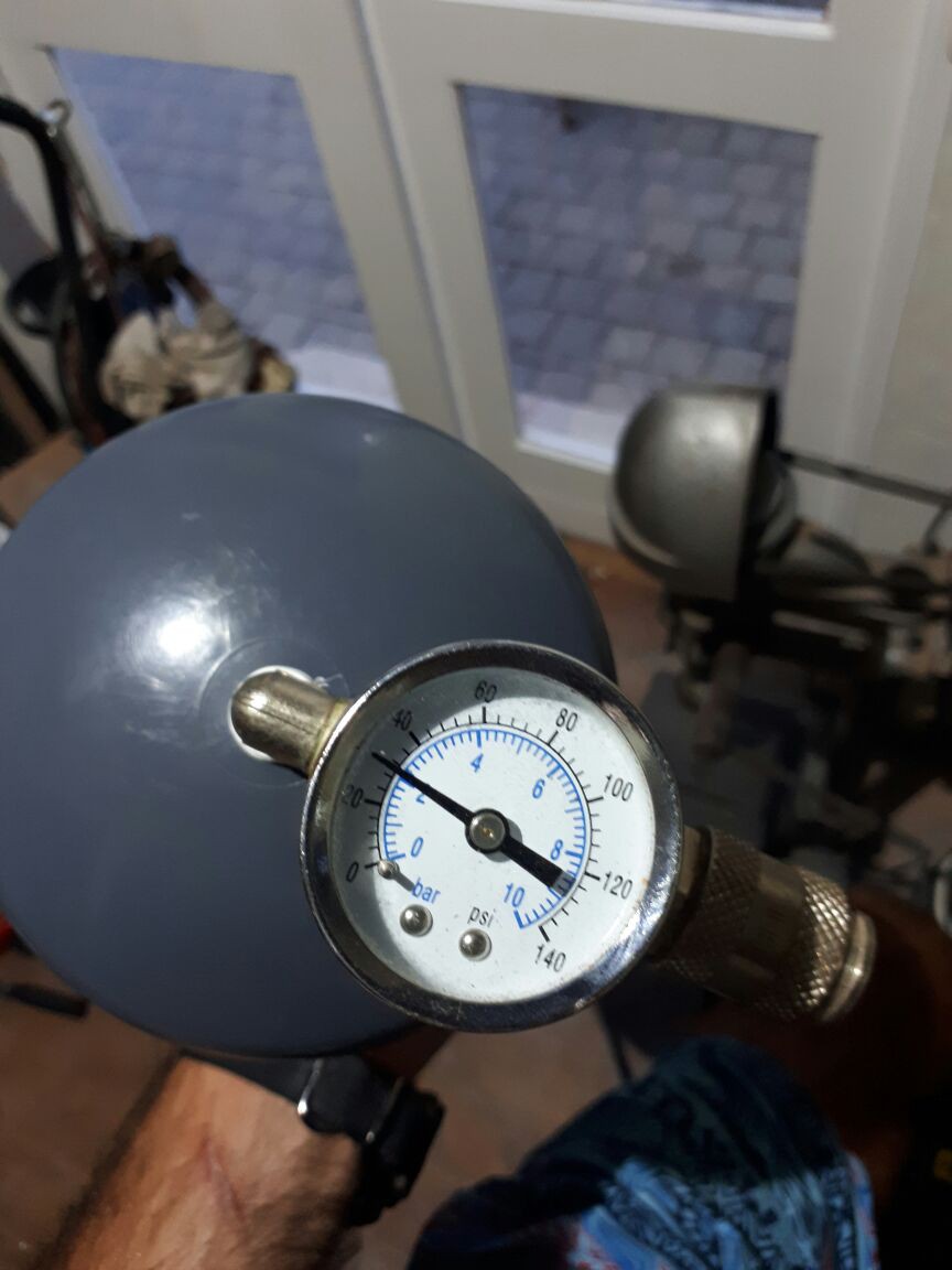
2. The housing could hold 2bar of pressue
3. The 5mm perspex lens leaked when pushed beyond 2bar
4. A 10mm lens was cut, it held 4 bar no problem.
4 bar is good enough for what I need.
Internals
From my last field test I learned that I need to pay more attention to the internal mountings of the units.
![]()
![]()
![]()
![]()
![]()
Software
Here is some of the work I've done on the software side to get the project to alpha testing:
- Made USB drive automount
- Installed the I2C RTC
- Installed apache2 - to have a health webpage
- Wrote a python script that does the following:
- Get the date and time
- Takes a photo using raspistill command (picam has been producing poor photos- will investigate later)
- save the photo to the USB drive if it is present and name it the timestamp
- save the photo locally if the USB drive is NOT present
- check the available space on the disks
- count the number of files
- write health status to a json file
- Add script to crontab
Here are two photos to compare a raspistill and python-picam photo:
Default photo taken from python-picam:
![]()
Photo taken using the raspistill command (exposure mode set to 'beach')
![]()
Moving forward
It's already obvious that there is a need for more power and better power management. A slightly longer housing will suit more batteries better.
Internal mountings should NOT be overlooked as easy. I will consider a small distribution board to tidy up the wiring and mount the RTC in a sensible way. The current internal cradle is made from hardboard, but a plastic or perspex one would be nice.
For power management I would include a Arduino via I2C to the raspberry pi to give current and voltage reading from the battery. The Arduino could then control the interval of switching the Raspi ON/OFF. The Arduino can also sport an LDR to only switch pi if the light levels are sufficient.
On the software I would make a simple web page displaying the following diagnostics:
- Power levels
- Disk usuage
- Latest photo
Software also need to be able to handle low power states and full disk events
Current Testing
The pipecam is ready for a set of Alpha tests. I had to stop myself from throwing it in the water straight away. The dry test will help correct the photography and get an idea of the system endurance. Minimum endurance should be +2hours (or anything better than a GoPro). The estimation on theoretical values has the endurance at around ~5hours. Test is set to take a photo every 5mins- which is what I believe I would be using for the first set of water tests as well.
-
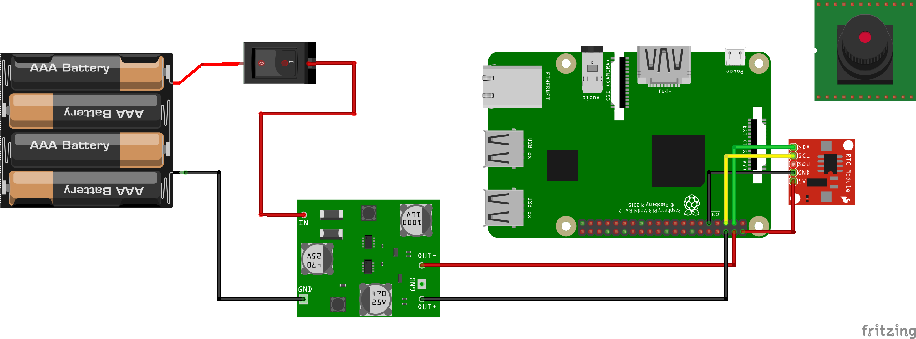
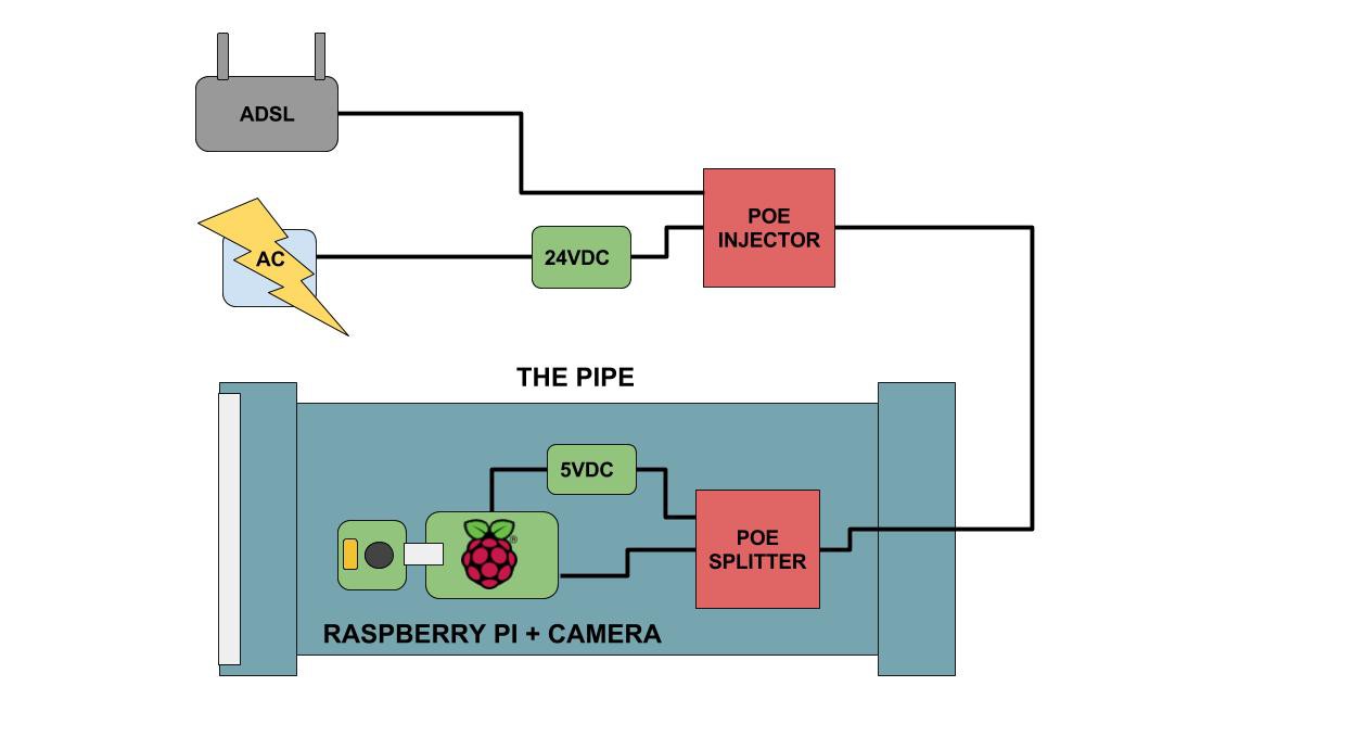
Block Diagram
07/21/2017 at 18:53 • 0 comments![]()
-
Housings: Failures
05/25/2017 at 18:49 • 0 commentsThe housing is one of the two key parts of this project: the "underwater" part of "underwater camera".
Here I've failed a few times already. This log aims to show the failures and explain how they were tested and why they failed, specifically looking at the lens interface.
These are mostly jumbled thoughts with many typos and grammar mistakes.
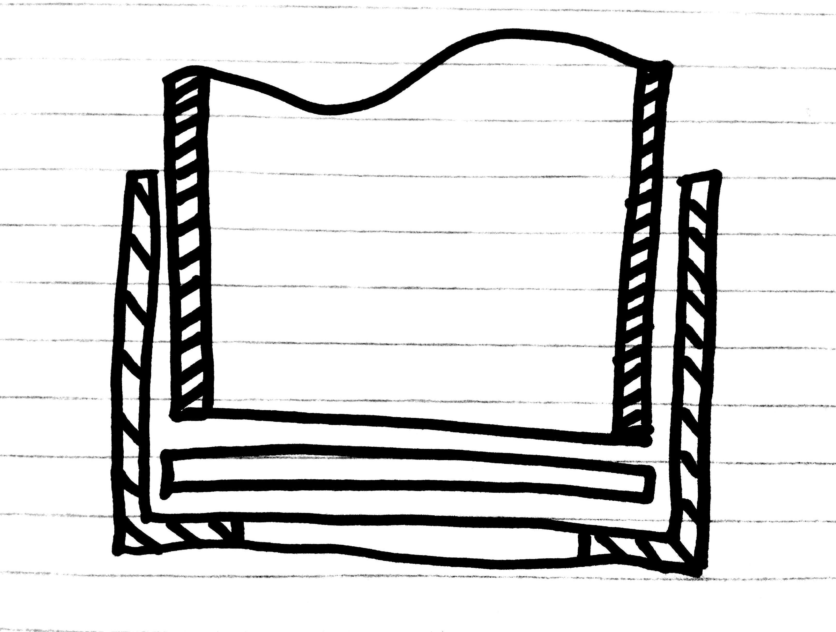
The basics
- Tube:
- 110mm PVC Waste water pipe was selected as the base chassis for the housing. This is because it is cheap, easy to find, relatively durable and provides ample space for electronics on the inside.
- Lens:
- Lenses was cut out of 3mm clear Perspex (Plexiglas or acrylic glass) sheets by use of a jigsaw. This was what I could find from scrap Perspex collected from signage companies.
Housing 1
The first idea was to use an off-the-shelf, screw-on access stopend for the lens on the one end and a female stopend on the other.
- The female stopend was glued in place with PVC-weld.
- The screw-on side was drilled with a hole saw to make a viewing port.
![]()
![]()
Then, to create a seal I made an o-ring. Making a custom o-ring is actually pretty easy. In this case I bought an o-ring from the pool section at a local hardware store and cut it to the length I needed for it to fit. I then used a drop of superglue to tack the two ends together. Hold in place for a few seconds and you should have a surprisingly robust o-ring.
![]()
The housing is then suppose to close with the o-ring seating under the lens, held in place by the screw on cap.
Problems:
- The area where the o-ring seats is too small.
- The o-ring was way too thick, leaving not enough thread for the screw-on cap to grip and create a decent seal.
- Apart from the o-ring being too thick, the amount of thread did not allow for much play.
- Leaked
This approach *might* work with a smaller o-ring.
Housing 2
For my second attempt at a housing I swapped the end caps around, using the female stopend as a lens holder.
I drilled the female stopend with a hole saw.
![]()
I the glued the perspex lens to the drilled stopend with PVC-weld and then glued the assembly the pipe with some pressure to clamp the lens tight to create the seal.
![]()
I then glued on the threaded access stopend to the back and used black silicon glue as a sealant, and screwed it on to create the back seal. I use black glue because it's easier to see where I've missed a spotted when cleaning the thread after opening it.
Problems:
- During my first water tests (dunking it in a bath) I found that it leaked on the back threaded end. I fixed this by applying more silicon glue. I the glue smeared it into the thread on both sides and then screwed the two parts together.
- On my second test, the housing withstood the bath, but could not hold up in 3m of water for 3 minutes. (I used the local dive shops pool for the 3m test).
- Leaking housing embarrassed me in front of a curious crowd.
- I then read up on bonding acrylic glas (the lens) and PVC (the pipe). Turns out that they don't play nicely and never really bond properly.
- To try to save this idea, I applied a generous amounts of clear epoxy both inside and outside in hope to form a lasting seal.
- On the next 3m water test the housing leaked again.
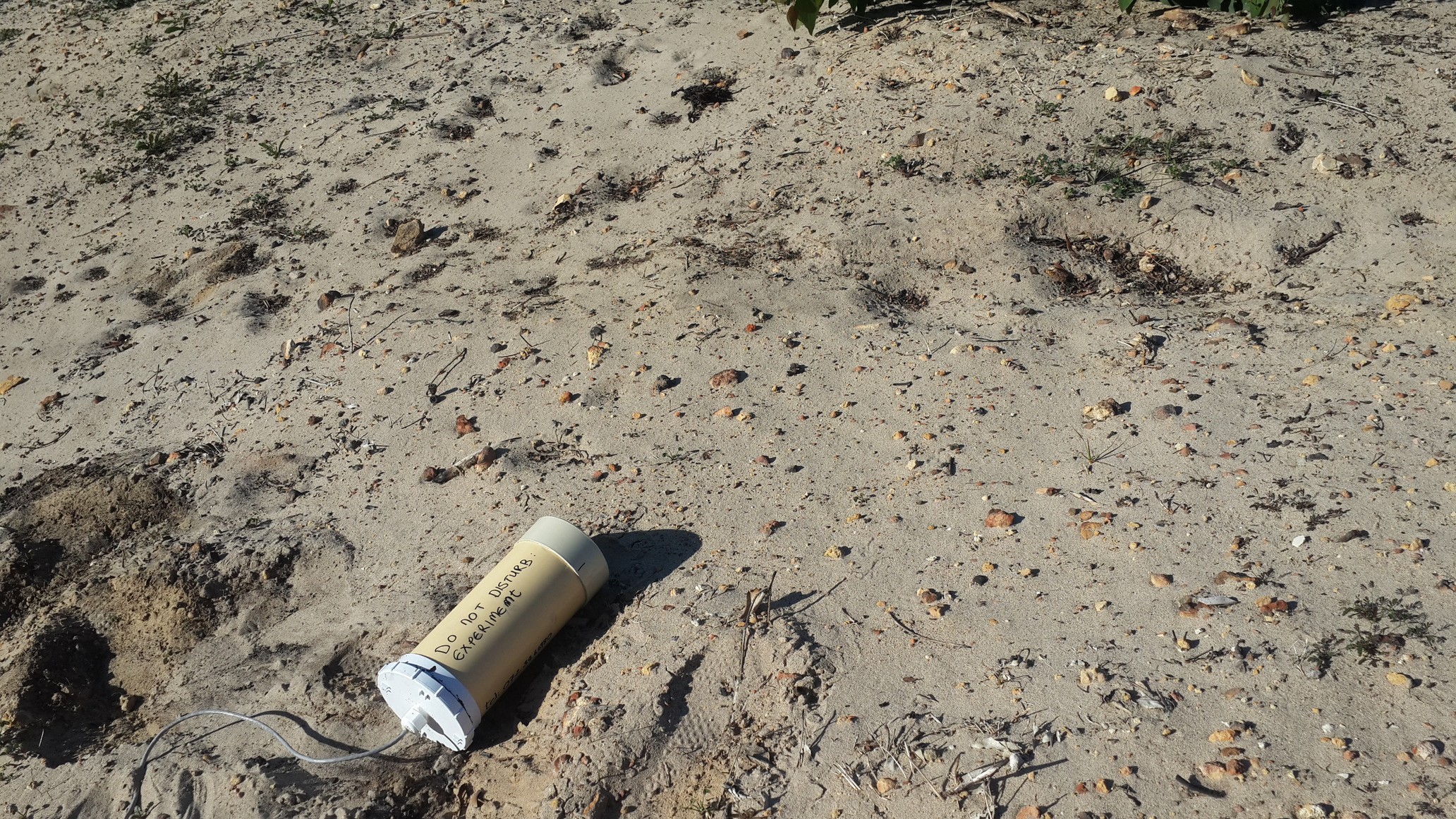
Housing 2 was used for a field testing on land while housing 3 was being brainstormed. The field test actually revealed that there is still a lot of thing to consider with regards to how the Raspberry Pi and electronics will be mount internally.
![]()
- Tube:
PipeCam: Low-Cost Autonomous Underwater Camera
Low cost autonomous underwater camera for long term deployments and exploration