STFDock
Turning a Griffin MultiDock 2 into a self-contained OpenSTF device lab
Turning a Griffin MultiDock 2 into a self-contained OpenSTF device lab
To make the experience fit your profile, pick a username and tell us what interests you.
We found and based on your interests.
stfstf init script (/etc/init.d/stf)Worldtalk - 1.62 kB - 05/16/2017 at 06:42 |
|
|
adb-serveradb server init script (/etc/init.d/adb-server)adb-server - 1.30 kB - 05/16/2017 at 06:41 |
|
With the init scripts for adb-server and stf now in place, and the stf init script tweaked to wait 10 seconds (for the wifi to connect) and automatically determine the Compute Stick's IP address to pass to `stf local`', nearly everything was set.
External USB ports for the Orico hub
In order to maintain the external appearance of a stock MultiDock 2, and to remove the need to physically modify the enclosure, I decided to replace a few of the MultiDock's USB ports rather than add additional ports. It'd start to get cramped if you tried to fit more than 10 devices into the MultiDock anyway, so it's not terribly limiting. I found some short USB extension leads with panel-mount ports on AliExpress, and once they arrived, I designed an adaptor plate to take the place of an original MultiDock riser card. It took a few revisions, but once I'd got it dialled in, I printed a few off. With the panel-mount ports I bought (and probably most readily available ones, unless you can find slimline ones), it's necessary to cut a small chunk out plastic off the body of the panel-mount socket; I could have designed an adaptor plate which didn't require this, but it would have been more difficult to print reliably, and would have made it bigger and bulkier. You can find the adaptor plate on Thingiverse.
Preparing the hardware
While removing the main PCB from the MultiDock in order to replace the USB socket with an internal USB cable (to plug into the Orico hub), I noticed that the internal power supply is quite potent - 12V @ 12.5A, or 150W. Since I was removing 3 of the original ports to replace them with ports from the Orico hub, I figured there ought to be plenty of power available - especially since most of the devices won't go anywhere near the 3A @ 5V which it could theoretically supply per port - to skip fitting a separate power supply in for the Orico hub, and instead power it straight off the 12V output of the MultiDock's PSU.
I removed the PCB from the Orico hub, soldered a wire link across the momentary power button so that it powers up automatically, and tacked a couple of chunky wires on to the power pins from the DC barrel jack. I then used some Sugru to mount the Orico hub at one end of the MultiDock, as well as to provide strain relief for the USB cable which is now soldered on to the MultiDock's main board in place of the original socket.
Assembling the STFDock
When the Sugru had been setting for a while, I attempted to assemble everything, only to realise that I'd mounted the Orico hub vertically - which meant that there was no space to plug anything in to it (spacious though the electronics cavity may be, it's not terribly tall). Luckily, I was able to get a spudger under the Sugru and prise the hub free, and remount it (with more Sugru, of course) onto the side of the MultiDock, where it just narrowly fits under the device shelf - but with enough space for devices to be plugged in horizontally. The power leads which I tacked on to the Orico hub simply screw in a pair of the MultiDock PSU's output terminals.
The Compute Stick fits nicely on the opposite side of the MultiDock to the Orico hub; as I may want to remove it at some point, I decided against Sugru, instead using some blu-tack. It doesn't have a lot of wiggle room anyway, though there are some exposed metal surfaces/objects which the HDMI plug could potentially bump into should the Compute Stick come loose - so I covered the exposed metal (and the HDMI plug) with masking tape before mounting the Compute Stick. Two USB cables run across the interior of the MultiDock - the micro USB cable which came with the Compute Stick to power it from the Orico hub, and the USB3 cable which came with the Orico hub, to plug the hub into the Compute Stick. The MutliDock is the plugged in to the Orico hub using the short USB cable which replaces the original external (upstream) USB port.
With the Orico hub and Compute Stick installed, I then reinstalled 7 of the 10 original riser cards (one port...
Read more »Starting on boot
Starting from a basic template, I created a couple of init scripts: one for the ADB server, and one for STF itself. RethinkDB comes with an init script - just follow the instructions (copy the sample config file into /etc/rethinkdb/instances.d and edit as desired). These init scripts worked, but at the same time I was writing them, I was also experimenting with various USB hubs (including the MultiDock's), and at one point ended up with a USB hub which I was sure had previously worked perfectly no longer playing ball with several devices. After much poking around, I discovered that the ADB server needed to be running as root in order to see and talk to all of the devices - even with the relevan udev rules (per the Android developer docs). I adjusted my init script accordingly, and didn't really think much more of it.
Ubuntu rebuild
Even after "caffeination", the Compute Stick wasn't anywhere near stable enough. The SUSPEND_METHODS="none" fix definitely put a stop to the auto-suspend after a short period of "inactivity", but after a while (anywhere from an hour or two to the better part of a day) it was still falling off the network for no apparent reason. I restored the Compute Stick to its factory state using the recovery partition (just as well I hadn't got around to removing it yet) and started fresh; a different project with another Compute Stick had revealed that the default Unity environment isn't as much of a hog as I'd initially thought (after tuning, at least), so this time I've stuck with that. Removing as much unneeded software as possible and tuning what I can (including installing compizconfig-settings-manager and disabling a bunch of plugins etc which I didn't want/need) has resulted in a pretty lean system which is happy to run STF on an ongoing basis.
USB hubs, revisited
Having ordered and now received the Plugable USB hub recommended by the STF documentation, it was time to figure out which combination of hubs made sense to use. I unboxed the Plugable hub to start testing, only to find that it had two problems: just like the Orico, it has a momentary power button, making it difficult to mount inside the MultiDock; and the two oldest devices (Galaxy Nexus and Galaxy S Wifi 4.0, both 6-7 years old) aren't detected at all by the computer when plugged into it. The power button turns out to be something of a non-issue, as it'll happily power up and work just fine with the button held in - so I can either short it out or simply mount it such that the button is permanently held in. The compatibility issue, however, is a bit trickier to deal with. A quick peek at the hub's innards reveal it to use FE1.1s [pdf datasheet] hub controllers, with no obvious way to change its behaviour (I suspect that it's the Battery Charging 1.2 support which causes the problem, as the devices in question charge happily but don't appear as USB devices). I then suddenly remembered that the compatibility issues I saw with the MultiDock matched those that I experienced with other hubs when the ADB server wasn't running as root, which made me wonder if I'd tested the MultiDock at the wrong time; I've now reassembled the MultiDock's innards, and sure enough, most of the devices work on it! Unfortunately, the old devices aren't supported (as per the Plugable hub), but plugging the MultiDock into the Orico hub gives a good balance - newer devices can be plugged directly into the MultiDock, while the older ones can be plugged into the Orico hub. Subsequent testing of the Orico hub has revealed that it also powers up without issue if the power button is simply held in permanently, so it's a viable option for legacy device support.
The revised plan
In light of the above, my revised plan is something along these lines:
After the software tweaking mentioned in the previous post, I was pretty happy with how it was running. A BIOS update got headless mode working with no other changes required; before the update, the Stick wouldn't boot without a display attached - just sitting there with the power LED lit but not doing anything useful.
I decided to leave it running for a while so that I could monitor for any memory leaks etc, and was rather puzzled to find that it seemed to die after sitting for about 5-10 minutes without any keyboard/mouse input (even if I was connected via SSH). The power LED stayed lit, but it didn't respond to any kind of input. I tried plugging the display, keyboard and mouse back in and booting back into the GUI, and found that it did the same thing. It seemed to be going to sleep / suspending itself, but I couldn't convince it to wake up - and no options I changed within the GUI seemed to change this behaviour.
I tried a few options found around the web (i.e. Ask Ubuntu), and eventually found one which works: set SUSPEND_METHODS="none" in /etc/default/acpi-support (and restart acpid). So far, so good!
The Intel Compute Stick comes with Ubuntu 14.04 LTS preloaded, running the full-fat Unity interface. In an effort to minimise RAM usage (to keep as much available for STF as possible), I've replaced Unity with lubuntu-desktop (LXDE) and removed a whole bunch of default packages which aren't relevant. If you choose to replace Unity with something lighter (such as Lubuntu/LXDE), it's probably a good idea to run `sudo apt-get clean` (and/or remove some unwanted packages) after installing lubuntu-desktop but before logging out of your Unity session, so that there's some storage space free; my Compute Stick ran out (a decent chunk of the already tiny 8GB is taken up by a recovery partition, which I may back up and then remove), resulting in neither Unity nor Lubuntu/LXDE wanting to start - both just showed the wallpaper after login, with no other UI, and wouldn't respond to anything. If you do get stuck in that state, try dropping to a console (ctrl+alt+F1) and running `sudo apt-get clean` in order to free up some space before you log in.
Closer inspection of the MultiDock's daughter boards reveals that the USB hub is connected to port 1 on the TS3USB221A. Per the datasheet, we should be able to tie the switch pin low in order to lock it to port 1. As the TS3USB221A is in a 10-Pin µQFN package, soldering directly to it would be a massive pain in the posterior. Luckily, the trace was reasonably easy to follow - a via right next to the pin drops it through to the back of the board, where it runs up to another via right next to pin 6 on the PIC. Each of the PIC's pins is almost as big as the entirety of the TS3USB221A, making it a much friendlier target for modding - and luckily, there's an ICSP header right next to the PIC, with a ground pin within easy reach.
Lifting the PIC's pin 6 from the board and soldering a jumper wire in its place, connected to the ICSP ground pin, does appear to have locked the TS3USB221A to port 1 - and one phone which didn't work with the unmodded MultiDock now happily works when plugged into the Orico hub via a modded daughter board. Unfortunately, that's not all that's needed; some devices seem to cause the PIC to switch something on the power rails (understandable, since it's trying to switch the port over to a dedicate charging port controller), resulting in the device's USB connection 'bouncing' continuously.
It's possible that the MultiDock's hub and/or daughter boards are broken, as I picked the MultiDock up second hand (well below full retail price) - and I've noticed a red LED blinking constantly on the MultiDock's main board, just beside the first USB2514B hub controller IC. With this in mind, and the lack of apparently quick-and-easy hack to make it work how I'd like it to, it's back to my original plan of removing the original electronics and replacing the whole lot.
Since the MultiDock's USB hub doesn't seem to be suitable for this project, it'll have to come out. I've done a bit of exploratory rummaging around inside it. As long as you have a T20 "security" torx bit (with a hole in the middle), the MultiDock is very easy to get into. Simply unscrew the back plate, then remove three screws and slide out the device tray, and the electronics are exposed. (Photos will be added soon - I need more light!)
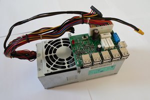
The internal construction consists of a metal-cased power supply, a large flat PCB which holds the USB hub controllers (3x SMSC/Microchip USB2514B) and a few other components, and a series of 10 vertically-mounted boards with the USB sockets and status LEDs on them.
Each of the 10 vertical boards is connected to the main board by a short USB mini-B male to mini-B male contains a surprising amount of circuitry, including:
I haven't reverse engineered the whole thing yet (far from it), but so far I've been able to determine that the TS3USB221A is used to switch the USB port between the USB2514B hub and the TPS2511 dedicated charging port (DCP) controller. I'm guessing that the PIC is deciding whether to switch it to the hub or DCP controller, and that my compatibility issues are being caused by it connecting most of my devices to the DCP rather than the hub. I'm not currently sure how it decides - but may be able to figure it out from a closer inspection and/or a bit of probing. A minor hardware hack to tie the TS3USB221A's port selection pin either high or low (depending on which port is which) may also be an option, if I can find a safe/easy connection point. If I can force the ports to hub mode, it'll still remain to be seen whether that allows the devices to draw sufficient current to charge (or at least maintain, rather than draining the battery).
While I wait for the Compute Stick to arrive, I have OpenSTF deployed on my old ThinkPad T430. Plugging the MultiDock into the ThinkPad, it was recognised as three four-port USB hubs (two of them are connected to ports on the third, providing a total of 10 usable ports for devices - 4 on each of two hubs, plus two on the third hub). This seemed like a good start, but of the four devices which currently make up my OpenSTF device lab:
It doesn't seem to matter which port(s) I use on the MultiDock - each device behaves the same, no matter which port (and thus which internal hub) it's connected to. This means that the MultiDock's original electronics are going to be useless for this project, but that's not a big deal as I've already got an Orico 7-port powered hub on the way which should hopefully work.
Create an account to leave a comment. Already have an account? Log In.
Although the project is now complete, I still need to sort through and upload some of the photos I took of the various electronics (MultiDock main board and riser cards, plus the Orico hub).
This project is great! Do definitely upload photos, will be waiting =)
Become a member to follow this project and never miss any updates

 Raphael
 rbtsco
 Martin
 Torbjörn Lindholm
Wicked Cool... Minds a spinnin now.....