-
A Window to the Soul
04/30/2017 at 18:59 • 0 comments![]()
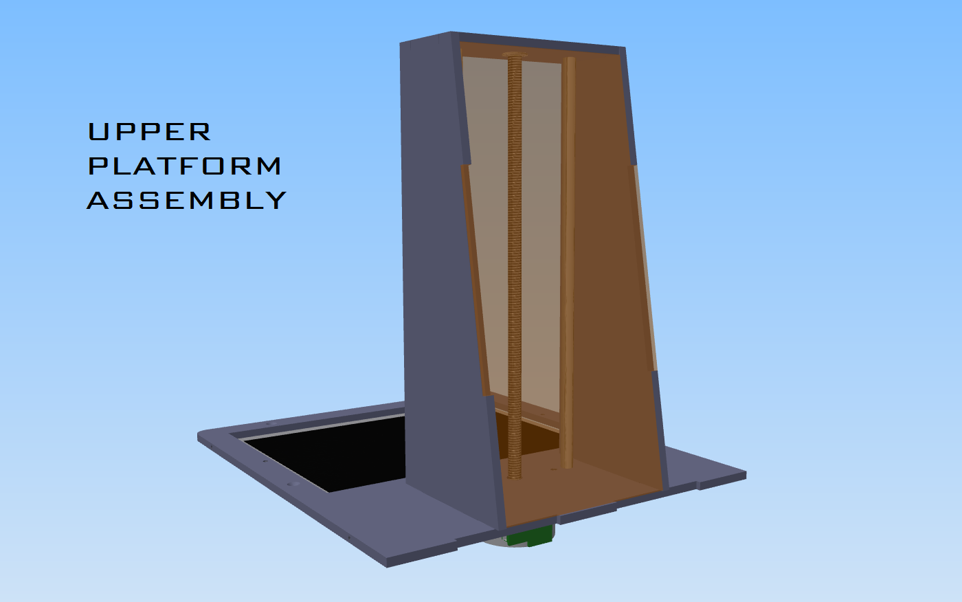
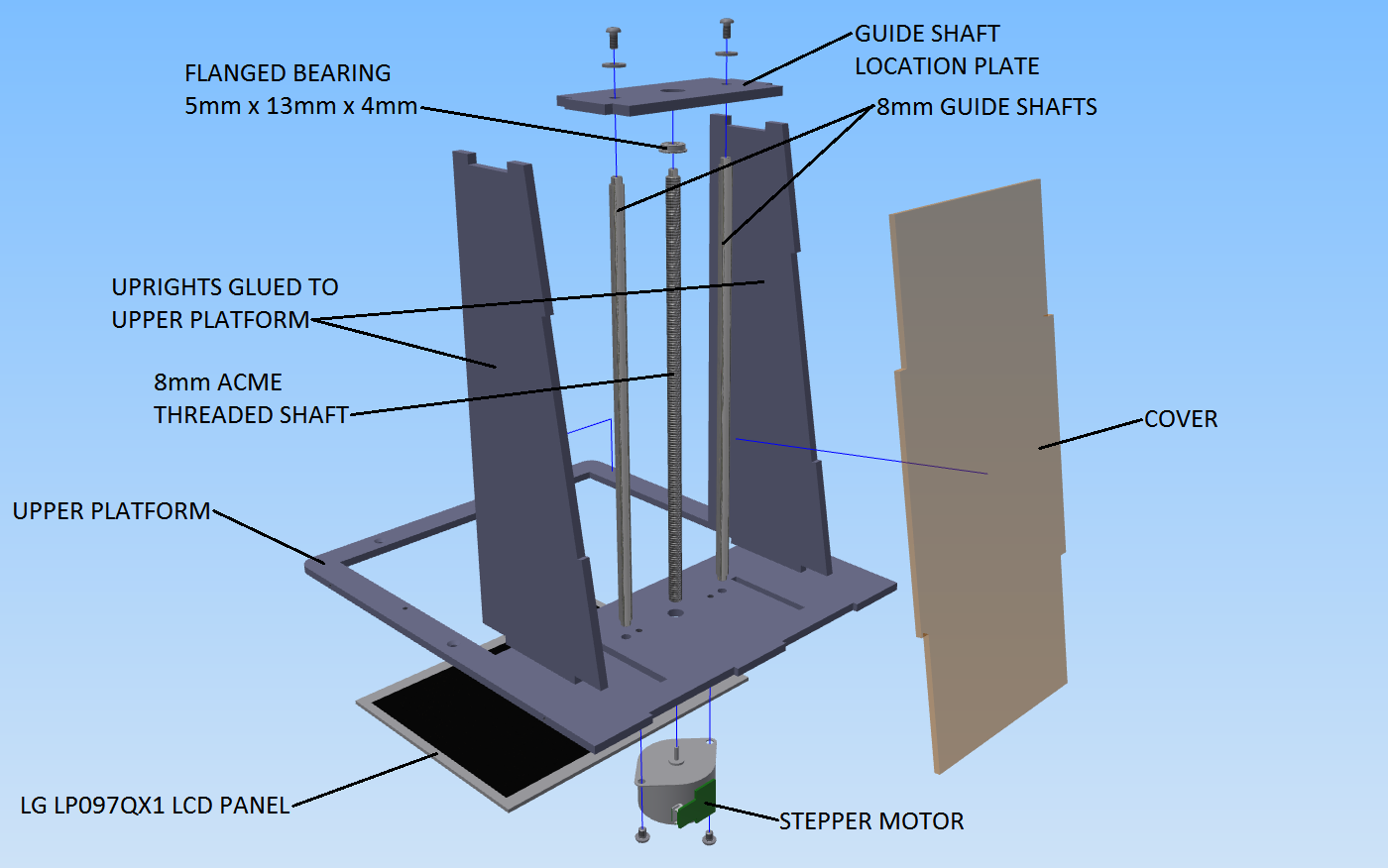
The upper platform will be responsible for housing the all important LCD display and guiding the build platform to the heavens.
![]()
The LCD display and stepper motor are fastened to the bottom of the upper platform from underneath.
The uprights are glued into the upper platform creating the support structure for the guide shafts and ACME threaded shaft once the guide shaft location plate has been screwed into place. The ACME threaded shaft is fastened to the stepper motor via interference fit and is radially located in the guide shaft location plate with a flanged ball bearing.
A cover is attached to the rear in order to stop light pollution in the build cabinet whilst the machine is in operation.
I am a bit concerned that the 8mm guide shafts are a bit flimsy for this build. Particularly when printing a large object. In future iterations I would like to move to either 12mm guide rods or, preferably, a guide rail with bearing block. For cost reasons and initial experimentation I think this will be okay though. A ball screw would also be nice, but that is very costly.
-
Up, Up, Up and Away!
04/30/2017 at 18:02 • 0 comments![]()
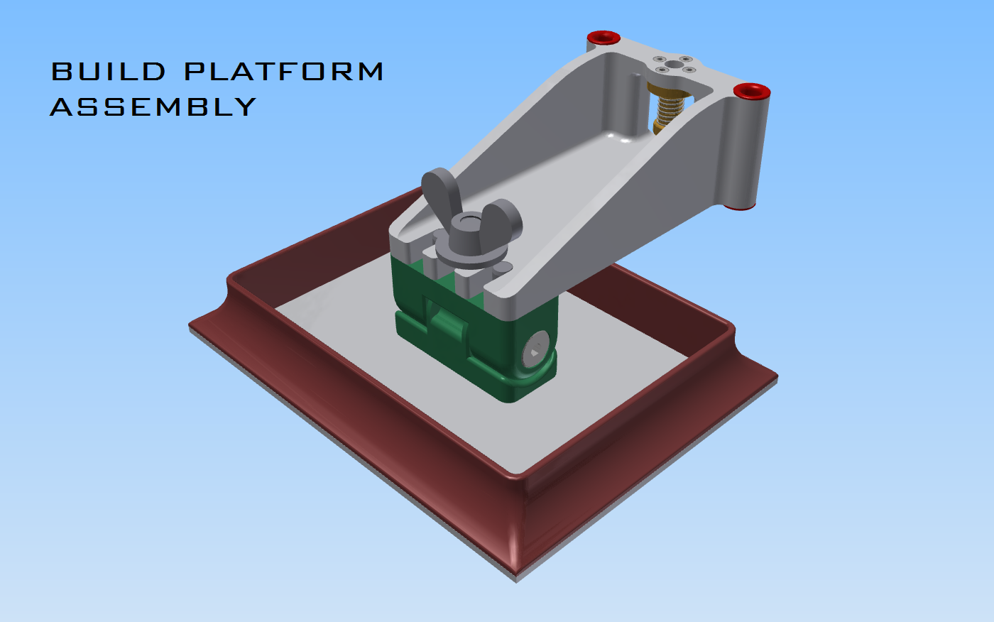
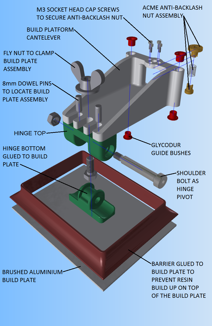
Most of the build platform assembly will be 3D printed by Shapeways or a similar service. This includes the resin barrier, both hinge elements and the cantilever arm. It would be fun to replicate these parts with the machine once the first iteration is built!
![]()
As can be seen above, the actual build platform is brushed aluminium plate. This is a light, durable material that the resin can adhere to and be removed from. Pockets underneath the hinge bottom and the resin barrier allow for them to be epoxy glued to the build platform.
The main function of the resin barrier is to prevent resin from pooling on top of the build platform as it raises out of the resin. Its secondary purpose is that of making the build plate more rigid.
The hinge is there to facilitate adjustment so that the plane of the build plate may be parallel with the plane of the LCD display. The pivot is a standard 10mm shoulder bolt.
The build plate, resin barrier and hinge make up the build platform assembly. The build platform assembly slides horizontally to and from the back of the machine so fasten and remove it from the machine. It locates in the cantilever arm via the 8mm dowel pins and then gets fastened by hand tightening the M10 fly nut.
The cantilever is guided up and down the guide shafts via the Glycodur bushes and is raised and lowered when the machine is in operation by the anti-backlash ACME nut.
-
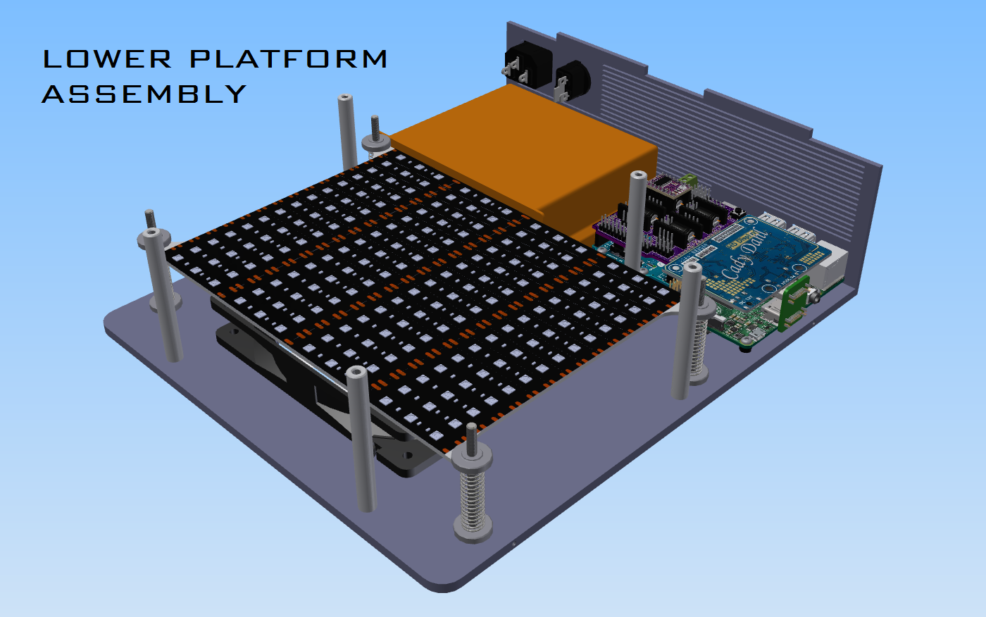
The Electronics, The Soul
04/30/2017 at 17:17 • 0 comments![]()
So I'll elaborate a bit more on what drives this project in this log. I have a little more hardware than required for an absolute minimum setup, but I will discuss why at the end of the log.
![]()
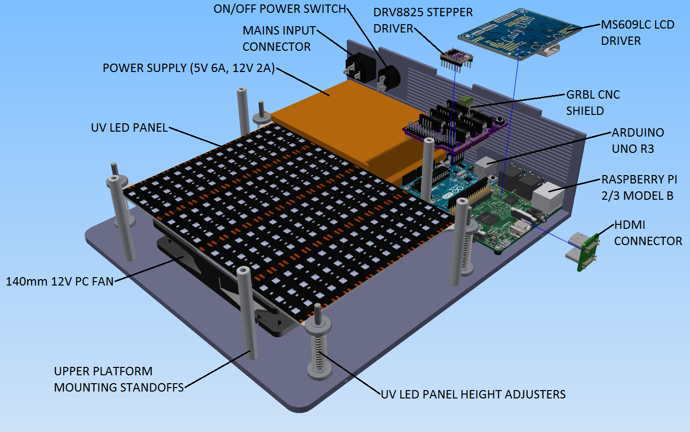
To start off, the project needs juice and for that I have chosen a dual output switch mode power supply giving 5V 6A and 12V 2A. 12V is required by the LCD driver, the LED strip, z-axis stepper motor and the 140mm PC fan, so 24W should be more than enough. The Arduino Uno R3 and the Raspberry Pi 2/3 Model B are powered by 5V.
The Raspberry Pi will act as the brain of the machine running Nano DLP allowing the machine to be networked. GRBL will be running on the Arduino handling the movement of the z-axis and keeping the limit switches in check. NanoDLP handles the slicing of the model and then the projection of each sectional layer. It also instructs GRBL when and how to move the build platform.
To connect the LCD driver to the Raspberry Pi an HDMI connector will be used that is commonly found in Raspberry Pi LCD display kits that mount atop the Raspberry Pi.
A Pololu DRV8825 stepper driver will be used to drive the stepper motor interfaced with the Arduino via a Protoneer GRBL V3.0 shield. This driver is capable of 1/32 stepping which means that the z-axis resolution will be 0.00016mm (0.9 deg/step stepper motor, 2mm pitch ACME thread).
The UV LED panel will be made up of UV LED strip that has a density of 60LEDs/m. The LED panel is height adjustable to get uniform light saturation through the LCD display.
Cooling of the electronics is achieved by the 140mm fan with the cooling path being from the rear of the machine through the vents towards the fan and out underneath the machine. Power is supplied to the machine via the mains input connector and then controlled via the on/off switch located on the back of the machine. The upper platform is fastened to the lower platform via standoffs.
As mentioned, there is some hardware in this setup that will become redundant, but I included it in the first iteration of the machine so as to give myself options and room to experiment. NanoDLP can handle the stepping of the motor etc, but I thought it would be nice to have a microcontroller in the machine so that if it is needed, it is there. It can handle extraction fans, tilting servos or anything else that I can't foresee at this point. If indeed only z-axis handling is required, then a simple stepper driver carrier board can be interfaced with the Raspberry Pi. I have also added in height adjusters for the LED panel as I need to experiment to find the optimal height for even light saturation projected onto the panel. Once I have established this I can replace them with simple standoffs.
-
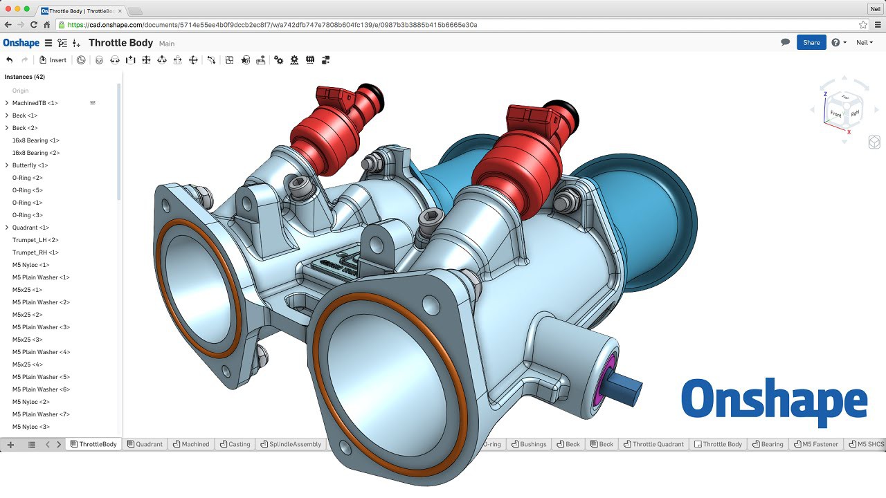
Moving to Onshape Soon...
04/30/2017 at 11:55 • 0 comments![]()
To further the Open Source cause, this project's CAD will soon be migrating to OnShape. Onshape facilitates a no limitations free account that hosts open source projects.
The reason I have chosen Onshape is because it is far more in line with other professional CAD offerings that I am used to. It also deals with version control automatically and allows contributions from anyone that wishes to get involved.
-
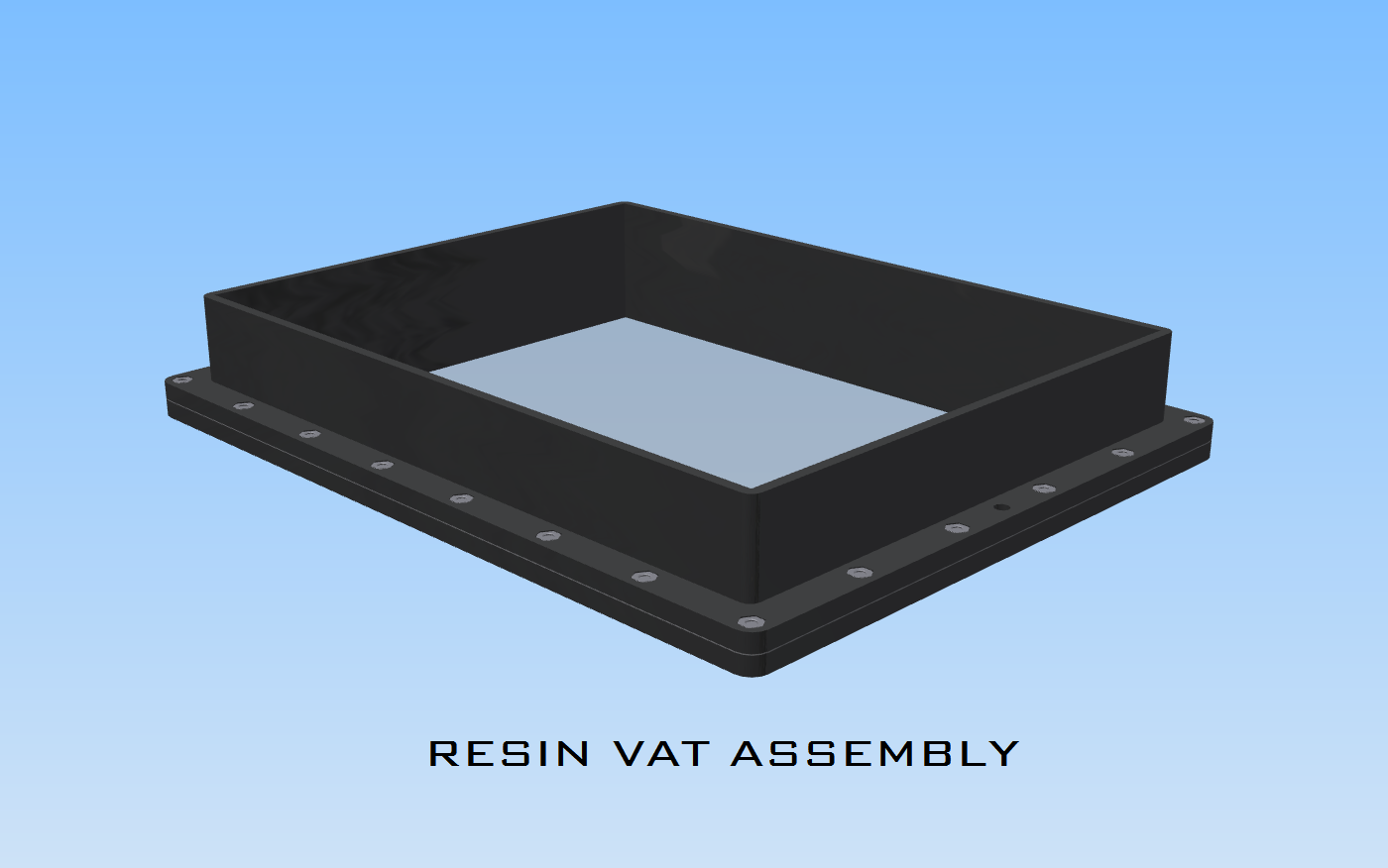
The Resin Vat
04/27/2017 at 11:58 • 0 comments![]()
The resin vat is far more important than first glance suggests, it is not just a vessel to hold the resin such that it does not get all over the place and cause havoc! Below one can see the construction of the resin vat...
![]()
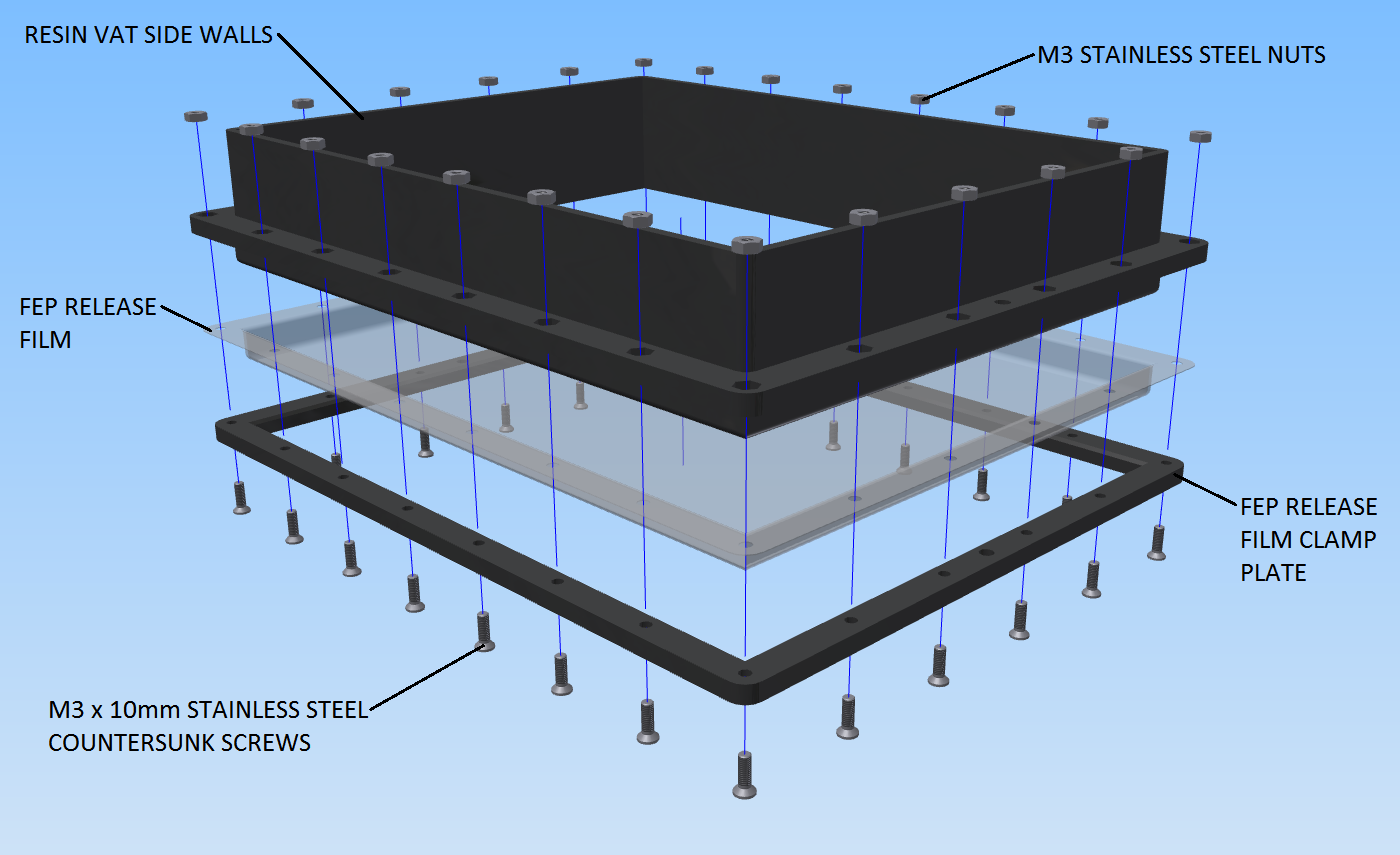
The crucial part to this assembly is the bottom floor of the vat which is made up of 0.3mm FEP film (Fluorinated Ethylene Propylene). Since this is the window to the soul of the printer, there are three properties of the FEP film that are important:
- UV and White light tranmissibility
- Releasability
- Flexibility
Since this version of the printer is an experimental platform it will accommodate both UV and White light sources. Thus the transmissibility of the light source is important, affecting both exposure and curing times.
Releasability and flexibility work hand in hand. Some printers incorporate a tilting vat to peal the most recently cured layer from the bottom of the vat. This helps to prevent the printed object from being pulled off the build platform and thus preventing a print failure. Using a flexible film eradicates the need for a tilting mechanism because as the print is rising after exposure, the film will deflect causing automatic pealing from the outside of the layer section toward the inside of the section.
The FEP film is a consumable of the the printer, for which testing must be done in order to determine life span.
The general idea for the construction of the resin vat is to sandwich the FEP film between the Clamp Plate and the Vat Side Wall flange allowing for even tensioning of the film as the fasteners are fastened.
Low Cost, Open Source, LCD based SLA 3D Printer
An open, superior, low cost alternative to FDM 3D printing that takes advantage of high res LCD technology and modern curable resins.