 Gintaras Valatka
-
1Step 1
All that is needed is Arduino and unused digital pins. Having a bigger board like Mega could accommodate more LDRs. All that is needed is digitalWrite(). The same board can also drive PWM pins to drive LEDs that drive LDRs.. clear? good!
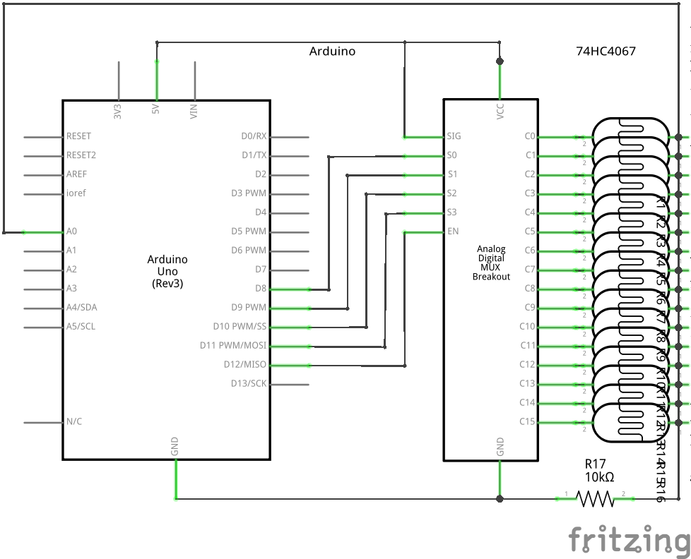
I wanted to have fun and used 74HC4067, 16-1 Analog Mux from Nexperia, http://assets.nexperia.com/documents/data-sheet/74HC_HCT4067.pdf
so the instructions part, of switching on/off 5vdc will be based around muxing, the rest is pure arduino, use anything that shines the light, use port expanders, go bonkers !Yes, plugging Analog Mux Z pin(common input or output) to 5vdc and driving LDRs :D (it can do Digital multiplexing and demultiplexing too)
![]()
-
2Step 2
Connect and play, please bear with me while I'm Fritzing, in the mean time here is some video candy
No numbers can ever replace a nice plot!
-
3Step 3
Use data sheet to find out the peak spectral response and tune your LEDs to that wavelength.
![]()
Having unbranded and undocumented LDRs makes the whole thing much more interesting. Might write a sketch for doing just that, finding LDR spectral peak response using RGB LED etc
-
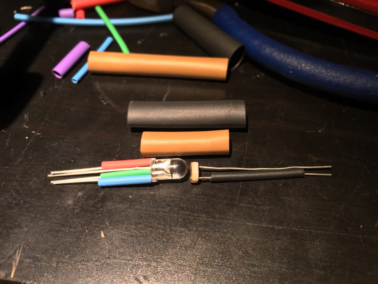
4Assembling Variable Resistor
RGB LED & LDR double insulated from any light with heat shrink tubing and almost ready for PWM - I used common anode(in my case - Arduino Due) As the board reboots, I get all the lights ON 'clipping' until the server connects to the board.
GinLab = GinScope, GinGen etc - Program ∑ Control ∑ Run!
UI is @GinLab https://hackaday.io/project/20700-ginlab-20700![]()
LDR Pot | Making | Matching | Plotting
[ In the quest of making programmable Lab ] First use case: controllable vRef for Adc todo: test it in signal chain

Discussions
Become a Hackaday.io Member
Create an account to leave a comment. Already have an account? Log In.