-
Bluetooth Module Mounting
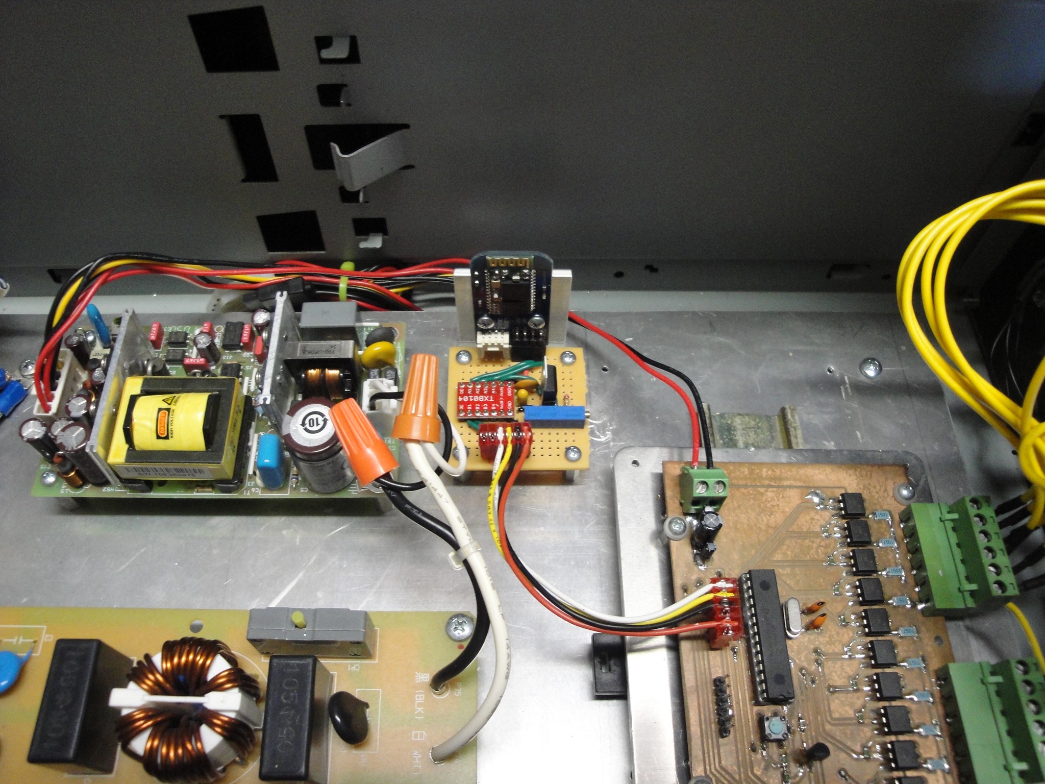
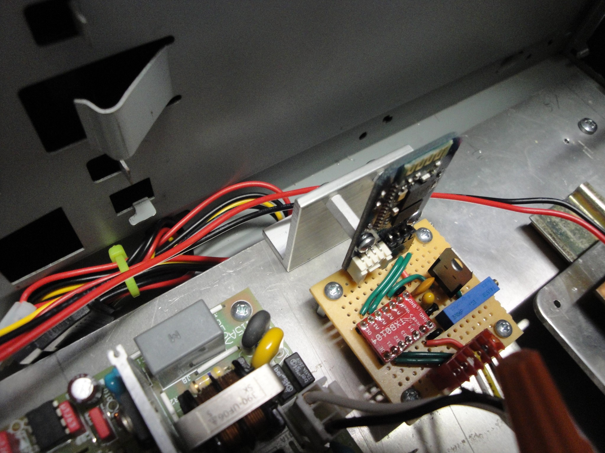
01/17/2015 at 22:34 • 0 commentsGot around to mounting the Bluetooth module inside of the controller box. The board was soldered up (as seen in a prior log) and the HC06 was only mechanically held to the main board via its electrical connections. This proved to be too flimsy. So an angled aluminum bracket was made to support the HC06. This can be seen below:
![]() Here is an overview of where the Bluetooth module is located within the controller box:
Here is an overview of where the Bluetooth module is located within the controller box:![]()
-
Claw Machine App
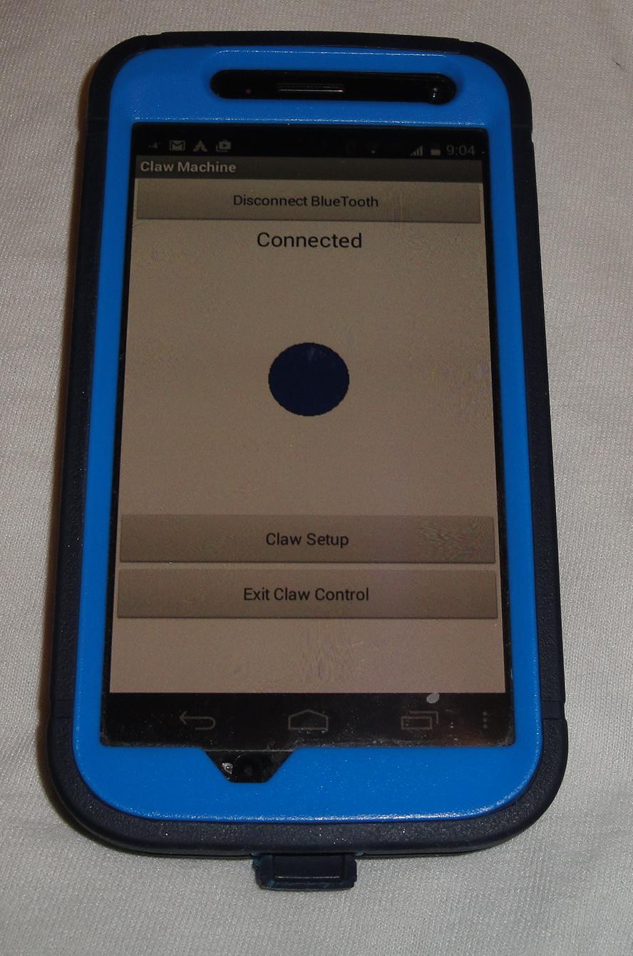
01/09/2015 at 01:50 • 0 commentsHere is a video showing the claw machine app being used:
The blue circle for controlling the movement of the claw has been replaced with an image of the claw.
-
Ideas to improve Claw Machine Control Options
01/08/2015 at 12:20 • 0 commentsThe way the app is built, will allow for an analog style of control of the claw machine. This would allow for a varying speed of the claw according to that control input. Right now the claw machine is incapable of taking in different speeds in a real time fashion. Instead a user would have to go into program mode to change the speed which would stop all movement.
So some more options for the I,J,K,L commands is wanted. The thought now is to add a single byte prior to the control command (I,J,K,L) that would contain the speed. This will range from 0 - 255. Similar to changing the speed of the claw machine in program mode only now it will be byte instead of ASCII. This way I will not have to use the ASCII to byte converter that is currently used.
The thought is to use the following format:
<begin byte speed input><byte speed><direction command>
Where:
<begin byte speed input> Single byte that will signal the claw machine that a speed/command string will be sent
<byte speed> Single byte containing the speed ranging from 0 - 255
<direction command> Currently used claw control commands I, J, K, and L.
This would be integrated into the serial interrupt routine. Currently the interrupt detects the I, J, K and L characters and fills a step count down timer and does not fill the receive buffer with the control character.
To sense the speed, the receive buffer will need to be used to remember the speed input. The speed will be placed into the buffer only if it sees the begin byte speed input. After it sees the speed it will adjust the stepper speed timer to the speed requested.
This opens up an issue where the with the current stepper speed timer. If this value is changed with the claw machine app, then the physical joystick will be forced to use that value for its control. It could be setup to allow for separate timers, one for the app control and one for the joystick control.
Along with creating speed adjust, it would be nice to include an accel decel feature. The abrupt starting and stopping of the claw movement would then be a nice transition.
This would have to be implemented into the stepping routine and would require another counter for the length of time to accel/decel. Which would be nice to be able to control in the menu structure.
As this is developing into more control and features, I would like to explore common protocols that are used in machine movement/control along a serial communications path. This might require a rewrite of the program which would force a spin off of this project with a completely different controller.
-
Claw Control App Change
01/08/2015 at 03:18 • 0 commentsTrying to make a cleaner look for the controls, I ended up switching to an image sprite on a canvas. The image is a blue dot and the user will move it up/down/left/right to control the claw machine forward/backward/left/right respectively.
![]()
To cause the claw pickup routine to initiate, the user will flick the phone.
What would be nice is to add an image of the claw instead of a blue dot, but this will do for now.
Also added to this is the capability to disconnect from the Bluetooth connection and a button to close out the application altogether.
-
Bluetooth Module/3.3V Power Regulator
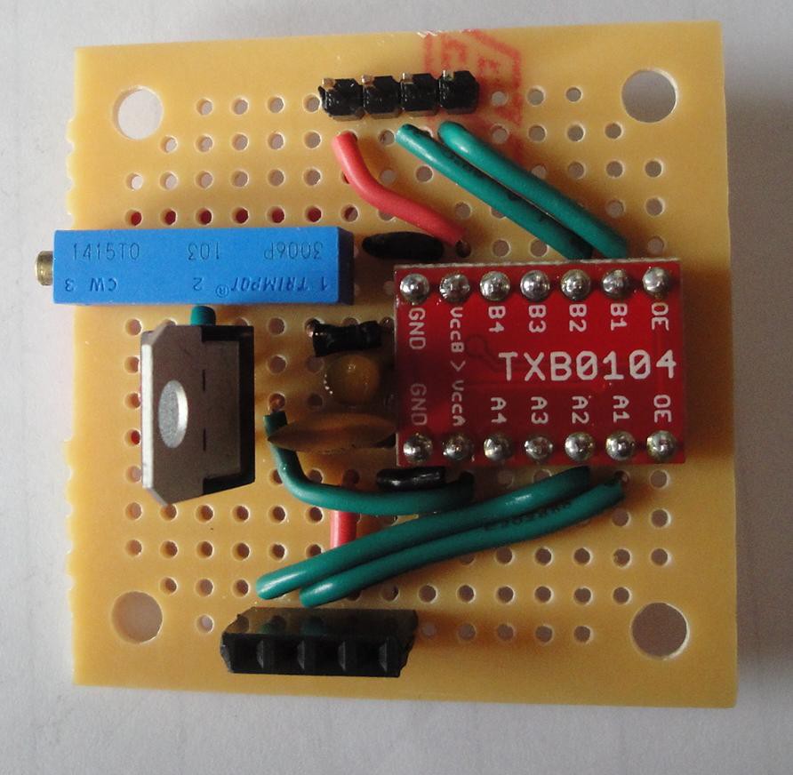
01/04/2015 at 01:50 • 0 commentsTo finalize the Bluetooth added feature, a small 3.3V regulator board was needed. Along with this, it was designed to also carry the voltage level shift and HC06 as a plugin.
The voltage regulator is an LM317 adjustable supply. This allows for an adjusable voltage output via a 10K pot (blue component in picture below). On the top of the picture is the header to attach the data/power cable from the Claw Machine board. Below that is a TXB0104 voltage level shift. This allows the 3.3V signal to translate to 5V and vice versa. Along the bottom of the picture is the header to attach the HC06.
![]()
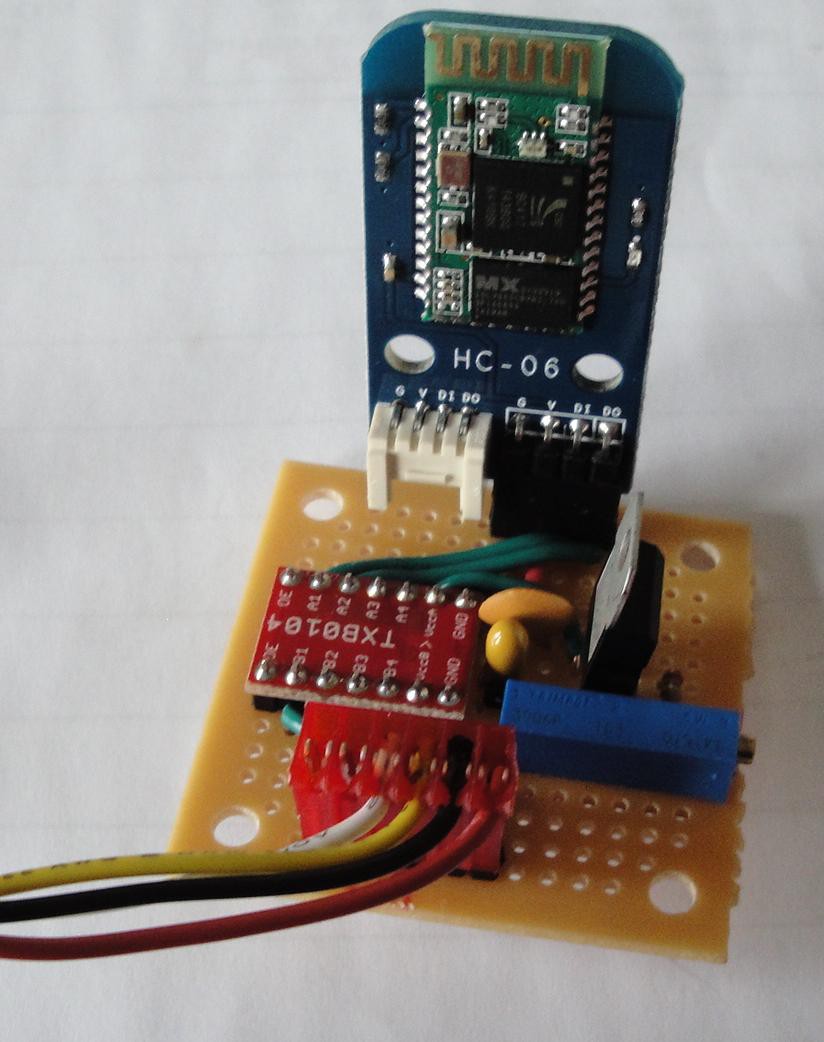
And here is the board rotate 180 and the data/power cable and HC06 attached:
![]()
Next is to find a location to attach fix the board permanently to the back plate of the claw machine control box.
-
App Creation
12/31/2014 at 01:26 • 0 commentsIn the prior log I shortly stated that the app was going to be made from scratch. This would be a deeper look into the app programming structure that I don't have the time for. Fortunately, MIT's App Inventor 2 is available for use. With this program, app creation was a lot easier than I was expecting.
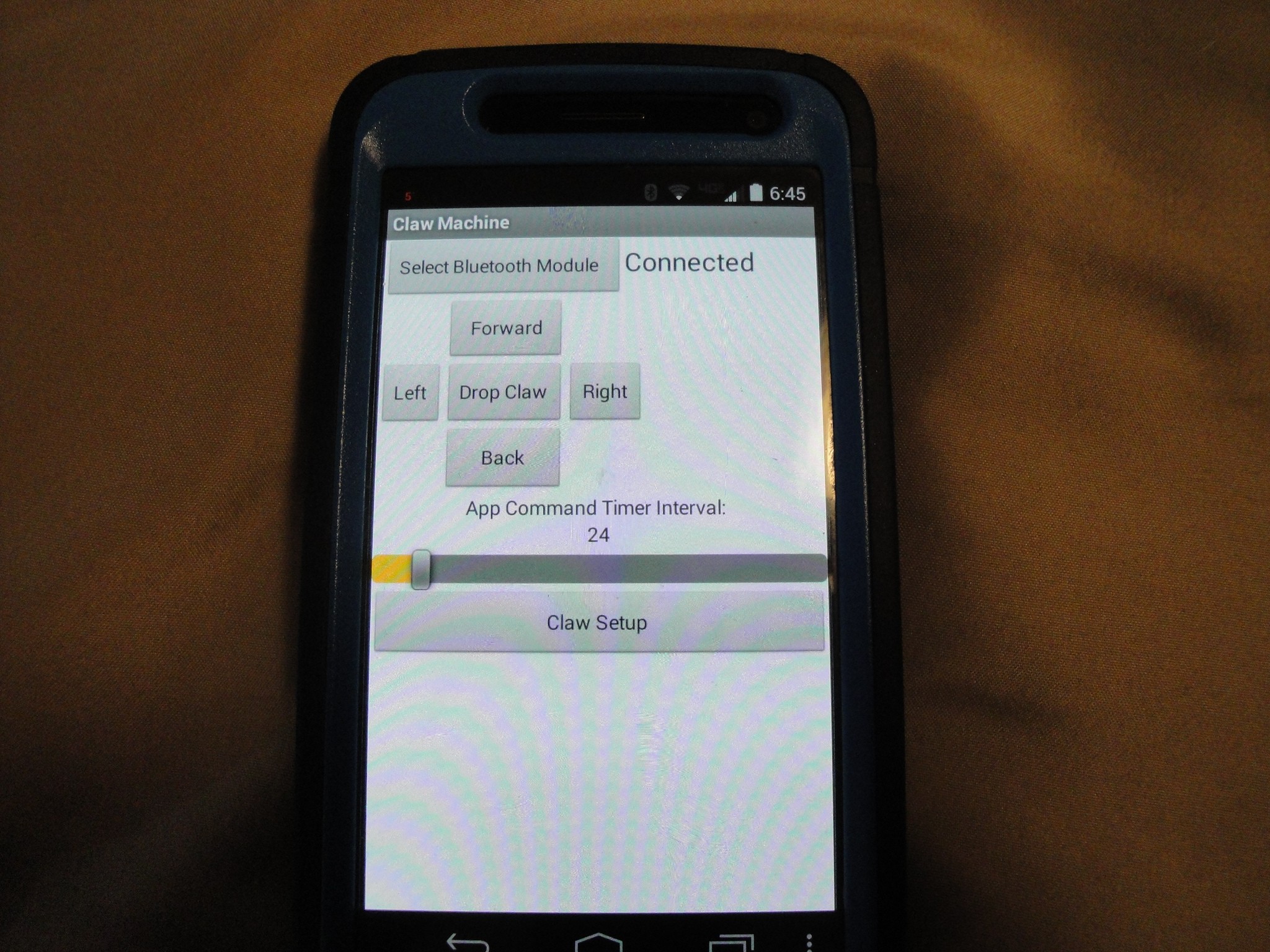
The app only uses a single screen as I had read that the same bluetooth client was not accessible from multiple screens. So a scrollable screen was made with hiding and showing the buttons/labels/sliders. Here is a snap shot after the user has linked up with the claw machines HC06:
![]()
The user will first see the "Select Bluetooth Module" button. After tapping on it and selecting from a list of known bluetooth devices, the other buttons, labels, and slider appear. To move the machine, the Forward, Left, Drop Claw, Right, and Back buttons are utilized. The "App Command Timer Interval" slider adjusts the speed at which the movement commands are sent (IJKL<spacebar>). This was to smooth out the start/stop tranisition when the commands were sent. Unfortunately, at around 40 (mS) there appeared to not be a difference when the claw machine would start/stop movement.
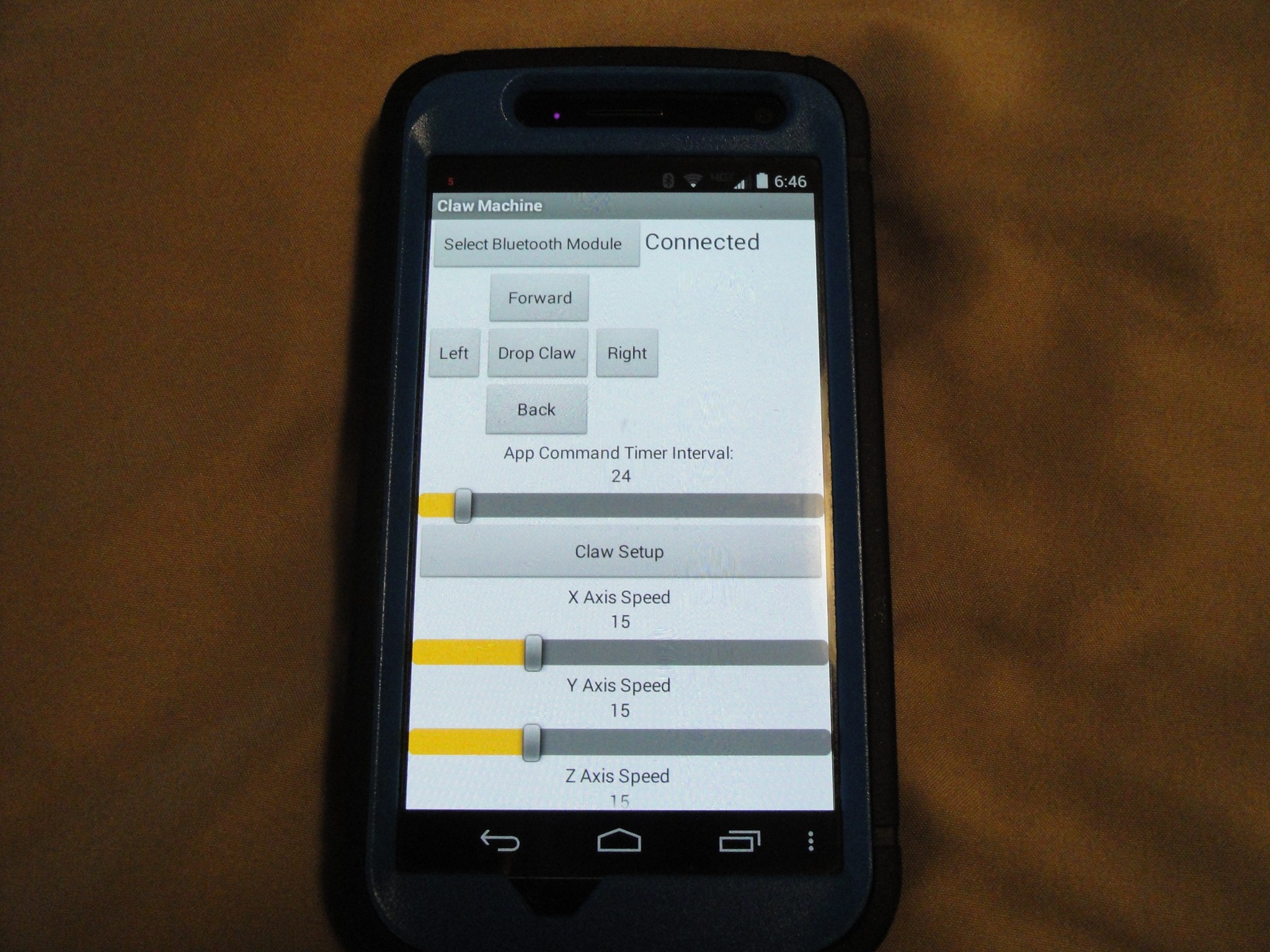
So the settings were added and could be adjusted by tapping on the "Claw Setup" button. This expanded the screen out to include the X Axis Speed, Y Axis Speed, Z Axis Speed:
![]()
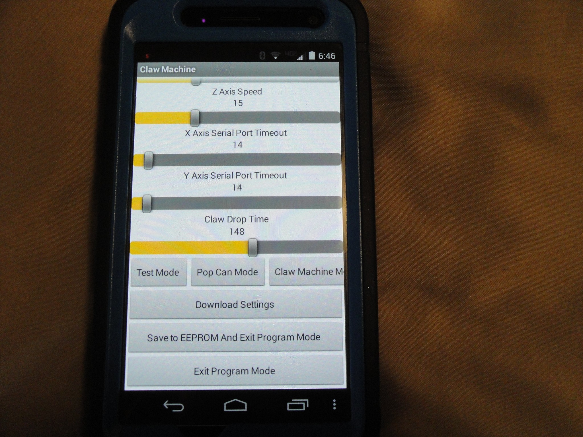
Scrolling down, X Axis Serial Port Timeout, Y Axis Serial Port Timeout, and Claw Drop Time are adjustable. The modes can also be switched from Test, Pop can, and Claw Machine (Mode is cut off and needs to be cleaned up):
![]()
To download new slider values, the slider will have to be adjusted. This is done via a flag for each slide that monitors if they have changed. If they have and the "Download Settings" button is pushed, then the changed values will download omitting the unchanged data. The bottom two buttons are to either Save the data to the EEPROM so power cycles will still retain the values, or just Exiting the program and keeping the values for only the current power cycle.
To help out with the start/stop pulsing that was seen when the direction controls were sent, the Serial Port Timeouts were adjusted to 100. This would force the axis to move longer lowering resolution of positioning, but at least it smoothed up the movement of the x and y axis.
The next step is to clean up the look of it so it looks more appealing. Prior to that though, the claw will have to be slightly modified to grab onto smaller cans (orange juice and apple juice cans), the table will need a grid of holes to locate the cans, and the back panel will need a door to allow for easier access into the play area.
The App Inventor 2 .aia file for the claw machine can be found here:
https://github.com/baden0001/Claw_Machine/tree/master/Software/Android%20App%20Files
-
Bluetooth Capable
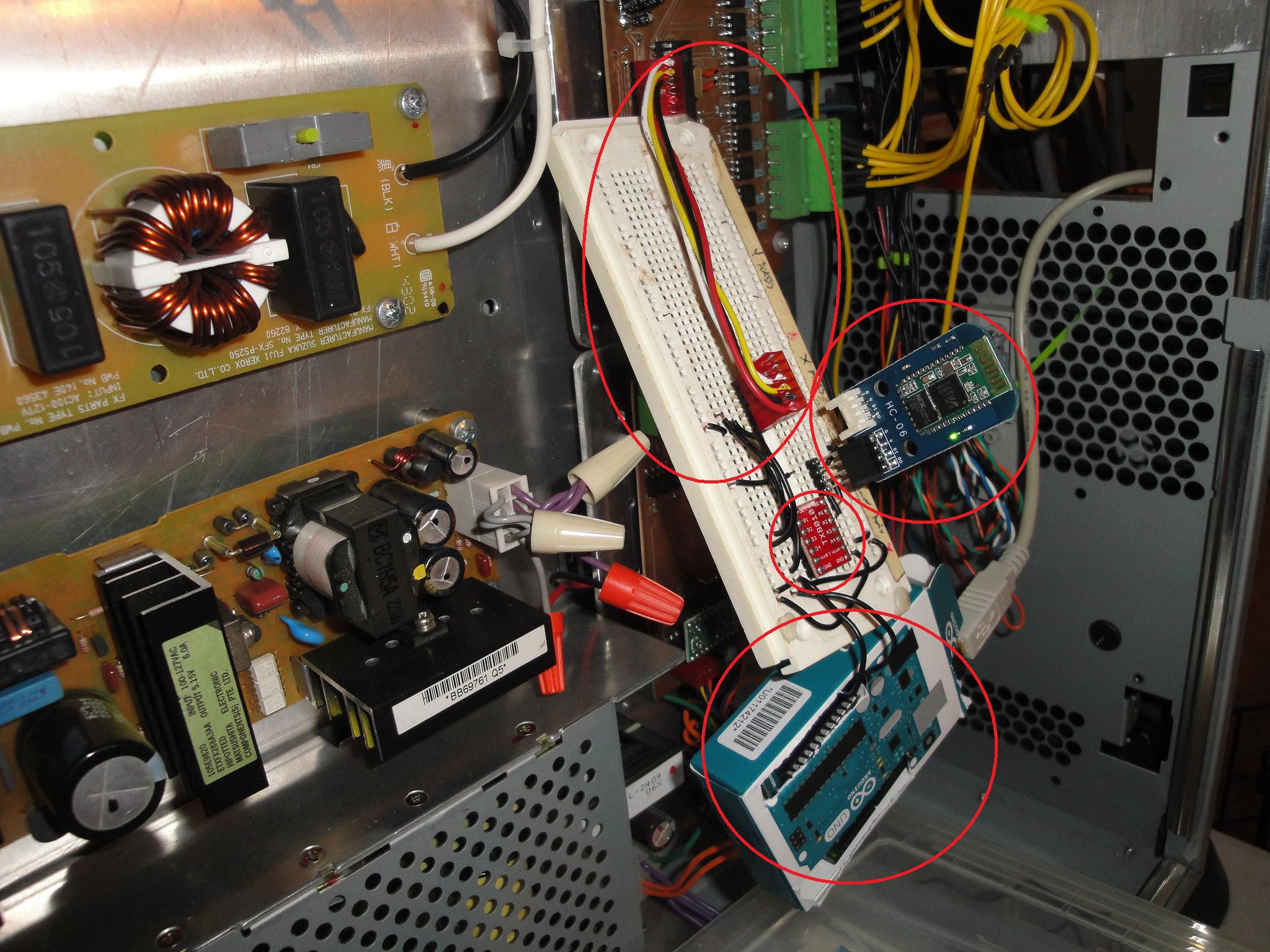
12/25/2014 at 16:05 • 0 commentsStill wanting to add the capability of using android apps to control the claw machine, I am making progress on this feature. Adding an HC06 made adding Bluetooth relatively easy. This is a serial Bluetooth device that is pretty straightforward to use. Supply 3.3V power and hook up the serial port to the claw machine serial port via a voltage level converter (the PIC that controls the claw machine is 5V) and Bluetooth capability is now available. Albeit I currently have it connected in a round about way. I do not have 3.3V power available inside the control box so I am supplying 3.3V power from an UNO.
Below is a picture of the setup. Starting with the upper left red oval, this is the serial/power connection between the PIC control board and voltage level converter. To the right of this is the HC06 device. Below left is the voltage level converter. And finally on the bottom is the UNO acting as a 3.3V power supply.
![]()
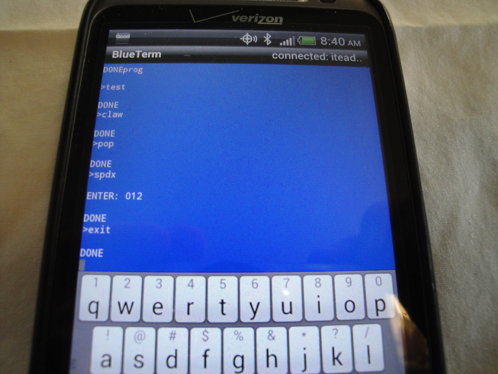
I then installed BlueTerm app to see if the PIC would respond to the interfacing. With the trials of getting the RX/TX lines correctly connected, the interface did work:
![]()
I could setup the different modes, change the speed and exit out of the command structure. Testing the quick controls, the machine would move. The only problem is causing a pulse of control commands as BlueTerm will only output a single character at a time and not send out multiple letters if the letter is held.
Next up is to build the app to control the claw machine. I have been looking through android code examples, but it will take some time to get a handle on how/what needs to be done.
Course of action is to keep looking for a generic robot control app that is easy to modify and to keep looking in creating the app from scratch.
-
Program Update
12/17/2014 at 03:46 • 0 commentsIn the process of getting the claw machine ready to pick up pop cans, the program has been updated to allow for serial commands to control. I, J, K, L, and spacebar will control forward, left, back, right and push button respectively.
This is in preparation to allow an app to control the claw machine. The details to the update can be seen in the release notes of the code as seen on the github page (address on prior project log).
Also, there is a new pop can mode. This will use the same main control code stages up to stage 5 of the toy pick up routine. This will bring the claw to the home position with the can stick grappled. The claw will then lower down to the bottom, open the claws, and then retract up. This will prevent the pop cans from being dropped from above.
The claw itself is also getting prepared to pick up pop cans. Not the full size cans, but instead the narrow cans. As time allows I will continue with the mechanics and post it on the "anatomy of a claw" page.
-
Code Release
11/23/2014 at 13:50 • 0 commentsThe code for the Claw machine can be seen at:
https://github.com/baden0001/Claw_Machine/tree/master/Software
This is written in assembly but is commented to explain simple functions. If there are questions, shoot me a message.
-
Updated firmware
10/03/2014 at 02:48 • 0 commentsAdded some more features into the program:
Shifting gears, I am planning on working on the claw next. It will be designed to pick up pop cans. This can either be a quick changing of the fingers of the claw or a complete redesign of the claw.
Added saving/retrieving settings from EEPROM
Added TimeZ variable being saved/retrieved
TimeZ adjusts the time that the claw drops in claw machine mode
This value is multiplied by 5
 Here is an overview of where the Bluetooth module is located within the controller box: