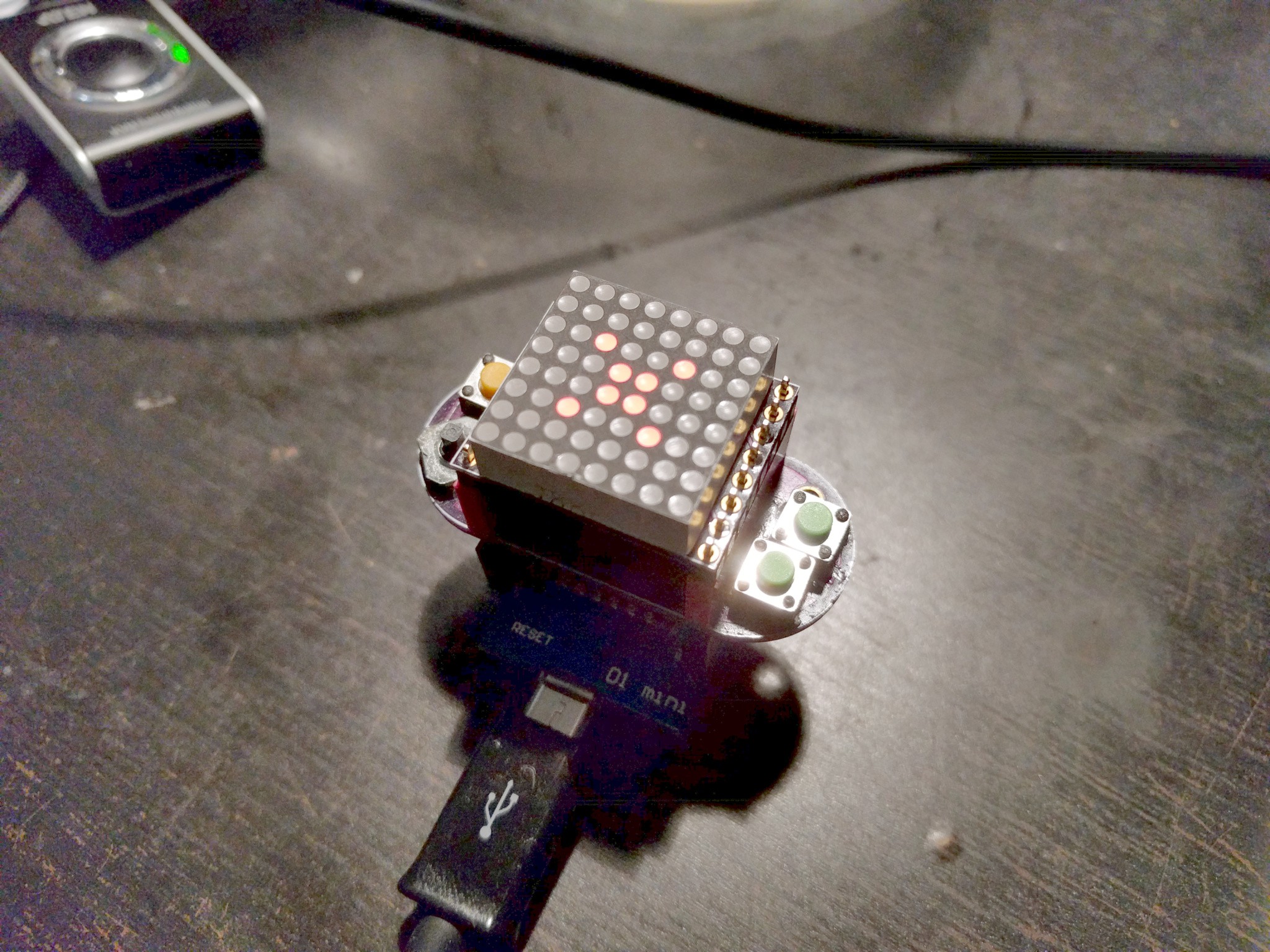
-
The Challenge
07/21/2017 at 11:27 • 0 commentsI'm in a ranty mood today, so I will write a little bit about why I decided to make this and how I hope it will work.
You have probably heard about the Raspberry Pi and the Micro:bit. Those projects are both parts of a larger effort to liberate people and give them back the control of their own devices. The modern computers, tablets, smartphones, game consoles and even toys are black boxes today. They are supposed to make you enjoy consuming carefully designed user experiences, without much thinking. Oh sure, they cater to your creative side too, letting you write comments with lots of emoji, upload user-generated content that you no longer own, or write a product review. In the mean time, as the population ages, we are running out of technically skilled people that are able to maintain and build those devices.
You might think that the obvious solution is to simply educate more people to do the technical jobs. But that doesn't work. The school doesn't teach you the important skills of an engineer. Schools are designed to kill the passions, not to make them grow. The best engineers out there are the ones who spent their lives tinkering with things, who were curious and fascinated with them, who needed to know how they work, needed to see for themselves, and then needed to modify the devices and make them their own. But you can't understand how a computer works today — it's much too complex a beast. And tinkering with game consoles can get you in the jail in no time. There are simply no stepping stones between a bright kid and an officially recognized engineer.
Raspberry Pi helps, because it gives a cheap computer that you can actually play with, that you can break and fix and break again, and nobody will lose their jobs because of that, like they might if you broke the family's computer. A computer that you can connect things to, and make it behave like a retro game console.
However, once you do all the soldering and connect the screen and joystick and put it in a cute box and so on, you simply load an emulator for one of the many old game systems, download the ROMs for the retro games, and continue consuming content as if nothing changed. Sure, you learned something about connecting wires and configuring Linux kernel hardware overlays, but you still have no idea how those games actually work, and you still wouldn't be able to make your own.
The Micro:bit is much better in that regard, as it is infinitely simpler and easier to understand, and you program it at a much lower level. You can program it at school and then take home and play with it even if you don't have a computer at home. You can show it to your friends and parents. You can make it do amazing things.
But you can only make very simple games on it.
There are only two buttons, and while you can use the accelerometer and compass as inputs, this is very limiting. Even worse, the 5x5 display is not very good for most games either. Sure, you can connect additional buttons and LED matrices or screens, but that requires much more experience, and you probably have to leave it all at school, as it's too unwieldy to carry around in your pocket.
So we need something simpler. Something that is as simple and easy to program as the Micro:bit, but more colorful, more convenient, closer to the "real" games out there. Something that doesn't require amazing graphical skills and hundreds of hours of work of artists, but still looks good. Something that you can program and take with you in your pocket. Something that plugs into an existing ecosystem of modules, extensions and tutorials, so that you are not left alone on your own. Something that is sturdy and rugged, so that it will survive being carried around in the pocket while you climb trees and fight pirates.
Physically, the device doesn't need to be complex. It should be small, it should have the familiar d-pad and fire keys, and a display capable of displaying colors. It should be low-resolution, so that you don't need to be a pixel-art wizard. It should plug into one of the existing development kits, preferably ones that can be easily powered with a battery.
Internally, it needs to be easy to program without any special software (which is a big downside of the Micro:bit) in a simple to learn language. It should come with a library that makes it easy to write the games, but doesn't take away the control. And most importantly, it should come with a detailed tutorial describing a dozen of example games, each introducing a new challenge and a new concept that can be learned to overcome it. Oh, and of course it shouldn't be more expensive than the original board it plugs into.
The target audience is a little bit older than that of the Micro:bit. Some of the concepts involved are quite difficult, and require more focus and abstract thinking than an average 11-yo is capable of. It's also not supposed to be taught at school, but rather be a standalone toy for self-study, similar to how the early microcomputers were.
-
First CircuitPython Program
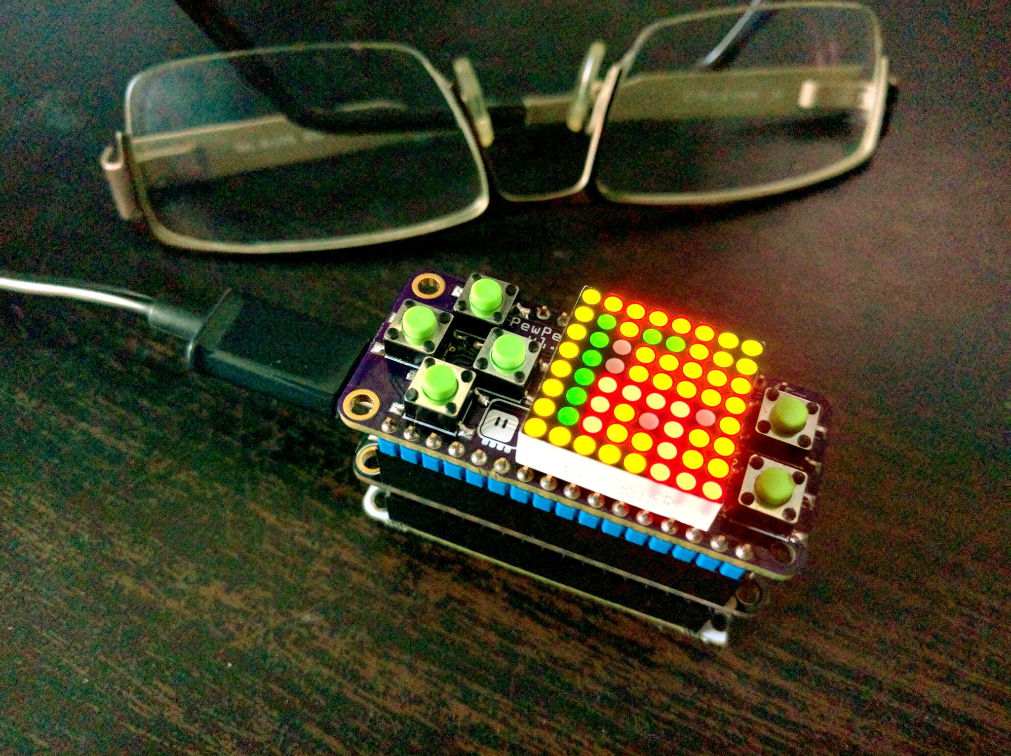
07/19/2017 at 21:58 • 0 commentsToday I found one more bi-color matrix that I have left (more of them are ordered for the next version), and used it to assemble a second PewPew Lite. I'm really happy with how it works, and I'm considering switching entirely to the Lite version — four colors are enough for most games, and really simplify things.
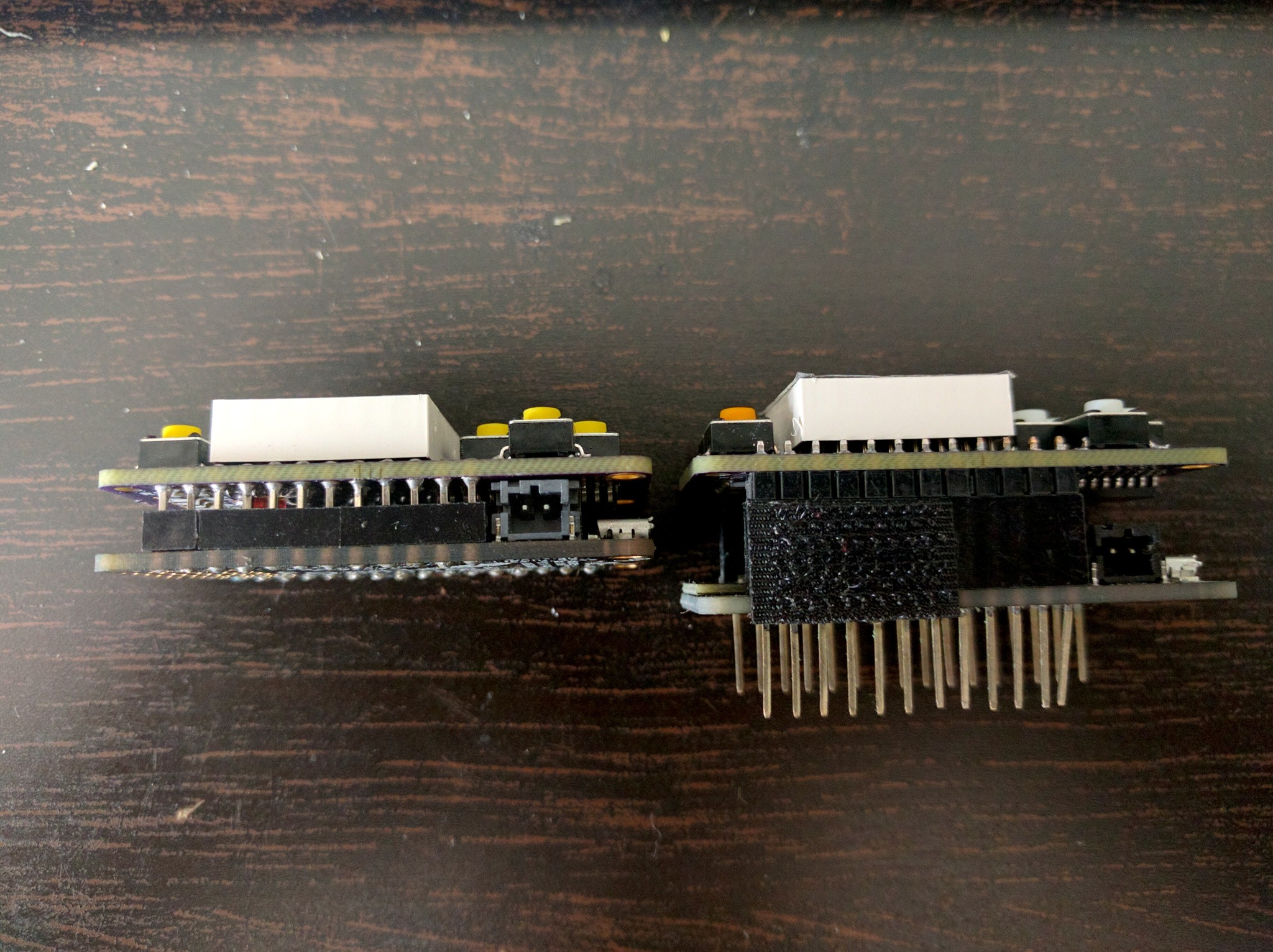
However, this time I decided to make it as flat as possible, so I used the 3mm female pin headers on the Feather board, and shortened the male headers. The effect:
![]()
Unfortunately it can't get any flatter, because of the battery plug and the chip on the underside of the shield. But one centimeter is still quite good. I wonder if I can find a LiPo battery that would fit in the space between the boards -- but more likely I will just stick the battery on the bottom.
I also wrote the driver for the CircuitPython (used MicroPython before that), and a simple drawing program:
import pewpew
import time
pewpew.brightness(0)
pewpew.show()
x = 3
y = 3
color = 1
hold = 0
blink = False
hold_keys = (pewpew.K_UP | pewpew.K_DOWN | pewpew.K_LEFT | pewpew.K_RIGHT |
             pewpew.K_X)
while True:
    keys = pewpew.keys()
    if not keys & hold_keys:
        hold = 0
    if keys & pewpew.K_UP:
        y = max(0, y - 1)
    elif keys & pewpew.K_DOWN:
        y = min(7, y + 1)
    if keys & pewpew.K_LEFT:
        x = max(0, x - 1)
    elif keys & pewpew.K_RIGHT:
        x = min(7, x + 1)
    back = pewpew.pixel(x, y)
    if keys & pewpew.K_O:
        back = color
    if keys & pewpew.K_X:
        color = (color + 1) % 4
    if blink:
        pewpew.pixel(x, y, color)
    elif back == color:
        pewpew.pixel(x, y, (color + 1) % 4)
    else:
        pewpew.pixel(x, y, back)
    blink = not blink
    pewpew.show()
    pewpew.pixel(x, y, back)
    while pewpew.keys() & hold_keys and hold < 15:
        time.sleep(0.025)
        hold += 1
    time.sleep(0.125)
As you can see, most of the code is dedicated to handling keys, including the repeating when a key is held down. The library is very bare bones for now, but I like the simplicity. I will probably need to add a function to display text, and some functions for scrolling around.
-
PewPew Lite Assembled
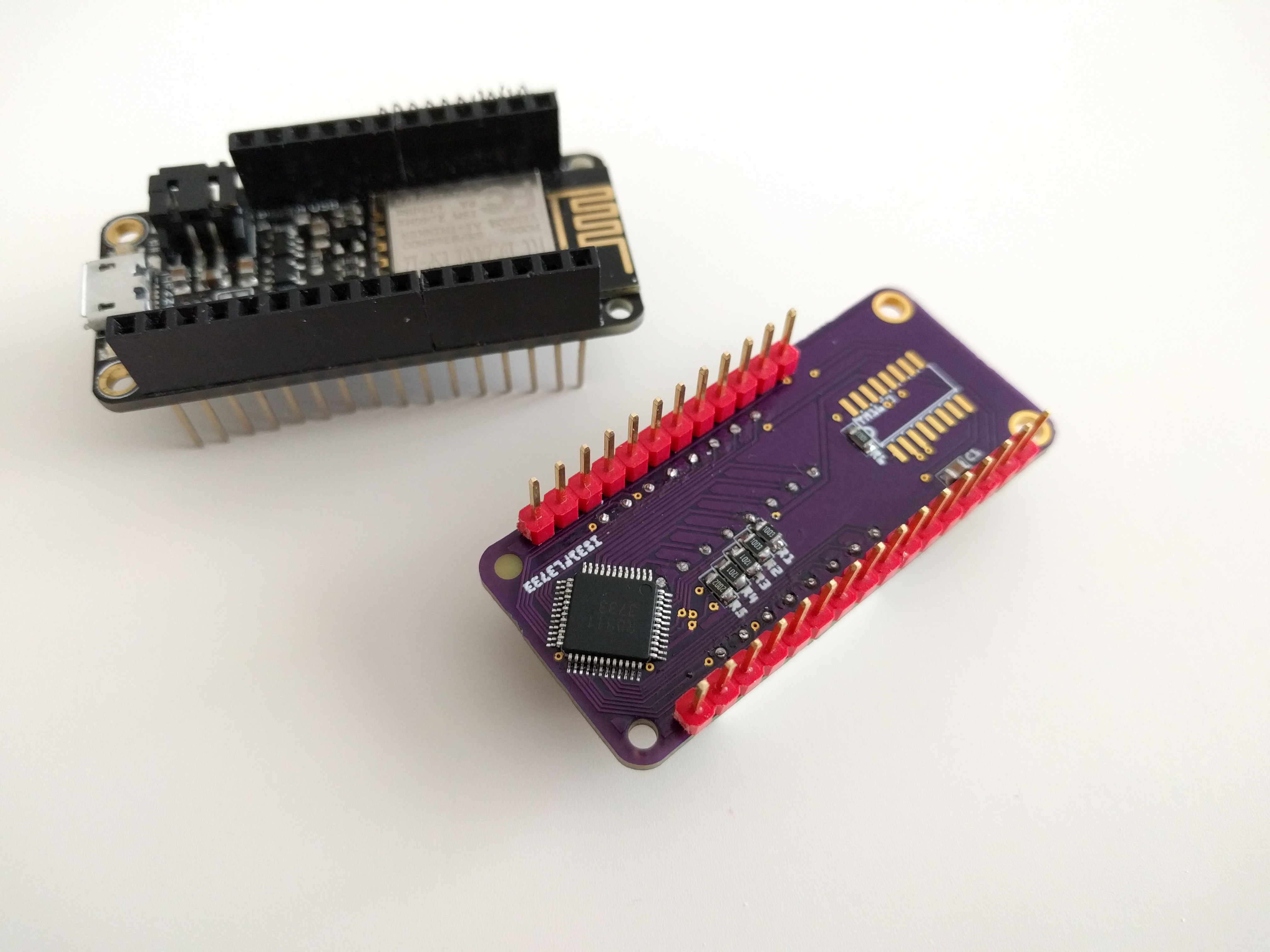
07/17/2017 at 16:40 • 0 commentsThe PCBs for the PewPew Lite arrived from @oshpark, so I assembled one and I'm really happy with it:
![]()
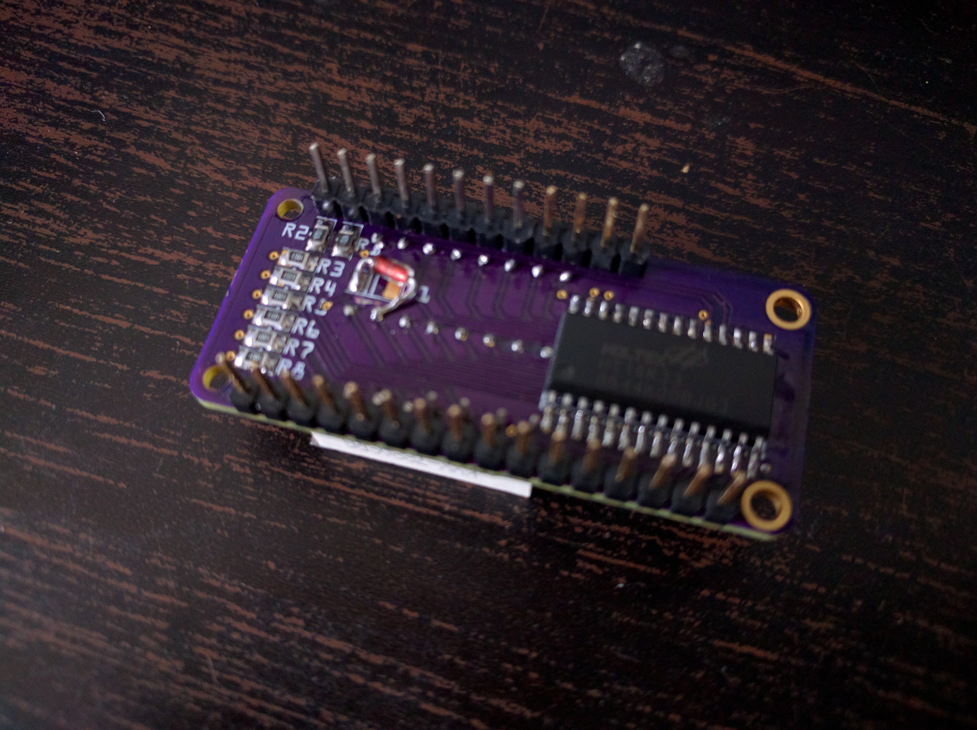
I didn't have an SMD diode at hand, so I just put a THT one there, and connected it to the correct pin (there was a mistake in the PCB, if you remember the previous log). I also quickly extended my HT16K33 drivers with a class for this board:
class PewPewLite(Matrix8x8x2):
    def _copy_buf(self):
        pixel = self.framebuffer.pixel
        _buffer = self._buffer
        for y in range(8):
            b = 0
            for x in range(8):
                color = pixel(y, x)
                if color & 0x01:
                    b |= 0x01 << x
                if color & 0x02:
                    b |= 0x01 << (15 - x)
            _buffer[14 - y * 2] = b & 0xff
            _buffer[15 - y * 2] = (b >> 8) & 0xff

    def keys(self):
        return int.from_bytes(self.i2c.readfrom_mem(self.address, 0x40, 2),
                              'little') >> 5
Nothing too fancy, just had to adjust the rotation and add a method for reading the keys.
I also received the PCB for #Ye Olde Nowt with the THT buttons, and now I'm thinking about how to use those buttons also with this project, as they are much more compact. Probably won't work, since I really need stuff on both sides of the PCB. There is one more type of buttons that I might try -- they are SMD, but use pads under the buttons, and not legs, like the ones here.
And of course I *really* need to start writing the games for this. I already have ideas of a dozen of them.
-
PewPew Lite Schematic
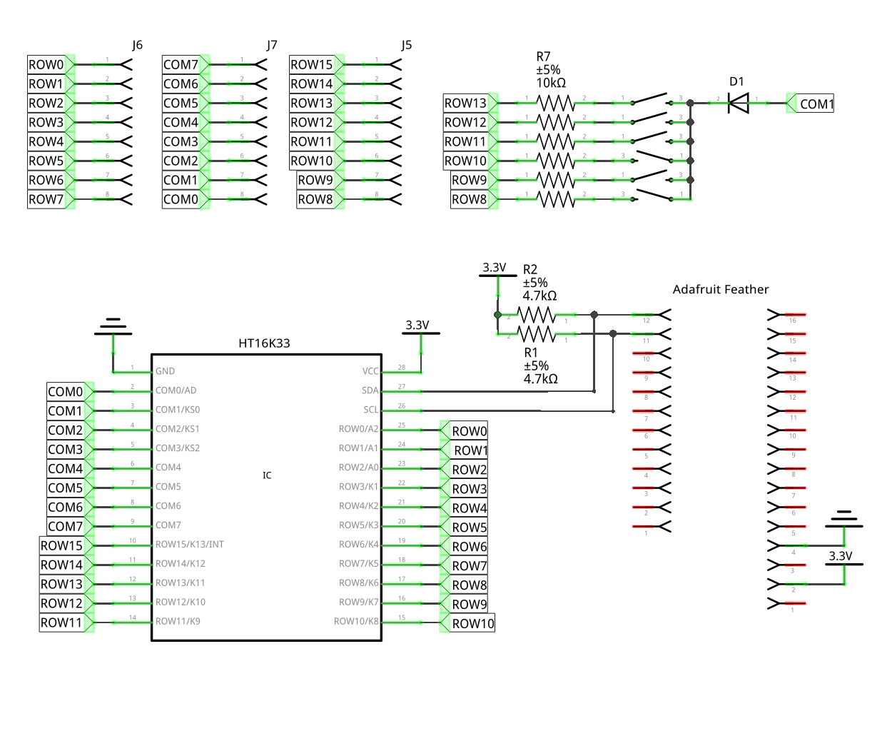
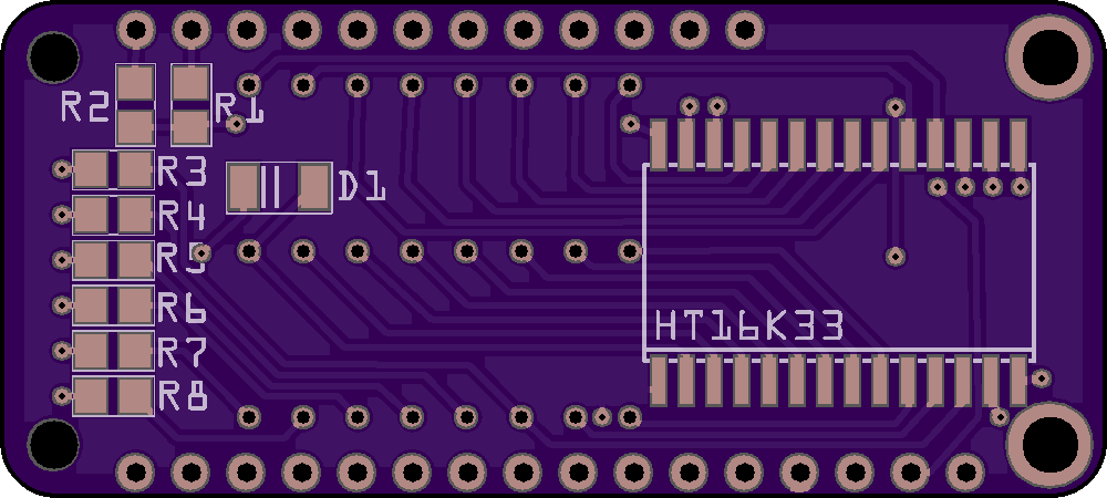
07/05/2017 at 21:53 • 0 commentsI decided to make a proper schematic for that PewPew Lite board I ordered recently. You know, so that it's more complete and also so it's easier to figure out what is what when I will be programming it. Most PCB programs force you to start with the schematic, and only do the PCB design later, but I'm using Fritzing specifically because it lets me do it in any order – and I get much better PCB layout this way, because many times it doesn't really matter which pin I use for a particular function, so I can as well just pick the one that is easiest to route.
![]()
Once I did that, I brought up the datasheet for the HT16K33 chip to see whether I will need a common cathode or a common anode LED matrix, and I noticed a grave error: the buttons are connected to the address select pin (COM0) and not to the buttons pins (COM1-COM3). Oops. (The schematic above has that already fixed.)
Of course I quickly corrected that. Fortunately, the two pins are close together and close the the diode, so it should be relatively easy to cut the trace and connect it to the other pin with a piece of wire. Still very embarrassing. I guess next time I should make the schematic before ordering the PCB.
-
PewPew Lite
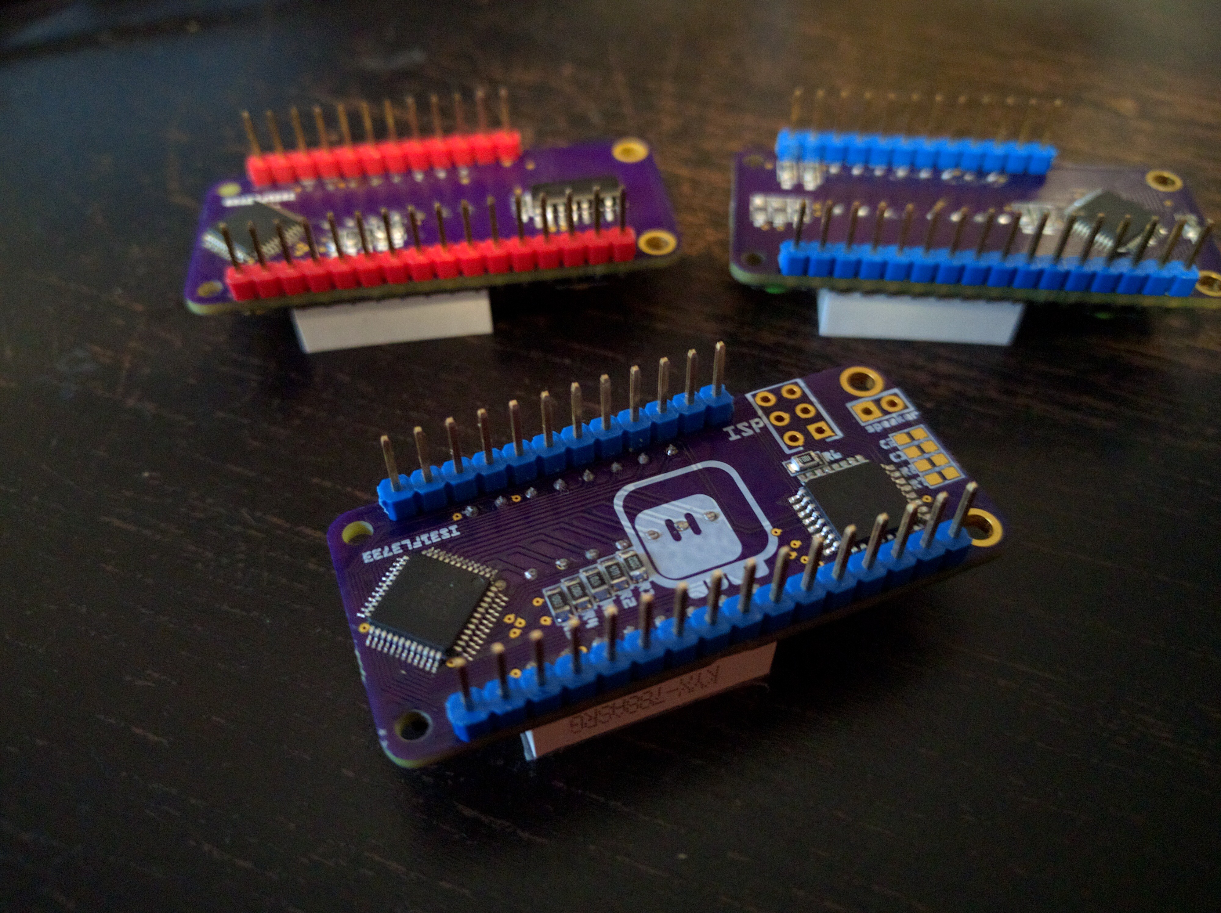
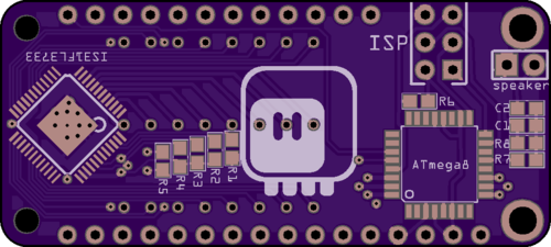
07/02/2017 at 22:42 • 0 commentsI decided to try and make a more minimalist version of this board, replacing the IS31FL3733 LED matrix driver chip and the microcontroller with a HT16K33 chip, which can do both LED matrix control and key scanning at the same time. It will have no sound. Why didn't I use HT16K33 in the first place? Well, the main reason is because it can only switch the LEDs on or off, and doesn't have brightness control for individual pixels. That means that there will be only 4 colors available for each pixel: black, green, red and yellow. On the other hand, this chip is cheaper, easier to source and much easier to solder by hand.
The plan is to write the libraries in such a way, that most games will work on both kinds of the boards -- as long as they don't require too many subtle shades of colors. It should still be possible to make Flappy Bird, Pong, Snake, Arkanoid, Space Invaders, Rogue, Boulder Dash or similar clones, and even have some board games like Checkers or Go. Chess would require much more colors, and it would be probably hard to remember which shade is which piece.
As usual, I will see how it all works when the boards arrive.
![]()
-
Version 1.5
06/18/2017 at 19:20 • 0 commentsThe boards for version 1.5 arrived yesterday, and today I had some time to assemble one. It didn't work initially, but after touching each solder joint with the soldering iron again, it started to work. Go figure.
Programming of the ATmega8 went smoothly, and it does appear as an I²C device together with the display controller, so everything seems fine. I will test the key scanning and the display library later. The sound code requires some more work before it's usable -- hopefully I will be able to beat it into shape soon.
![]()
I already have a version 1.6 PCB designed -- the only difference is that it has pads for an SMD speaker, and that the speaker is driven from two GPIO pins, not one and ground -- giving me one more bit of resolution and louder volume. I'm not ordering that yet, though, because I'm sure I will have some ideas for improvements while working with the version 1.5.
-
Sound
05/31/2017 at 05:01 • 0 commentsI got the blinking (actually breathing) support added to the IS31FL3733 library during the PyCon.US sprints, so now you can have a nice hardware blinking cursor. Back from the conference, and I started working on the next prototype.
Since I want it to have sound (simple 8-bit "pew pew" sounds, as the name implies), I looked around a bit for some kind of dedicated sound-generating chips. Turns out they are all pretty old, coming from old game consoles and computers, and not actually that easy to program. So I decided to put an 8-bit microcontroller on the board for generating the sounds. And of course, once I have the microcontroller there, I can drop the keyboard chip, as that microcontroller can also handle the keys.
So here's my list of requirements for that chip:
- at least 6 GPIO pins with internal pull-ups for the buttons,
- hardware I²C slave peripheral,
- at least 8-bit timer for sound generation with a decent speed,
- internal oscillator,
- small enough to fit on this board,
- easy to program,
- already in my drawer,
- cheap.
The minimum number of GPIOs is thus 10 (6 for keys, 2 for I²C, 2 for the speaker), so that rules out the ATtiny85 and friends. Looking through what I had on hand, I finally narrowed down my choices to two chips: STM8S003f2 and ATmega8. The first one is very cheap, the second one I already know quite well. I decided to start with the STM8, because it's always a nice bonus to learn something along the way.
So I re-created my dev environment and flashed the blinking LED sketch on a STM8 development board. So far so good. Then, just for kicks, I tried the UART example for it, but it didn't work correctly -- the speed was all wrong. Oh well, it's not like I'm going to need that. I even found a nice example of an I²C slave for this chip online.
Then I realized that I need to make sure it actually fits on the board with all the required components. But to determine the required components, I need to actually use a bare chip, not this dev board. So I found a universal breakout board, and soldered one of the chips on it. Then I tried the blink example on it. Hmm, strange, it programmed fine, but the pin only goes up and down a fraction of a volt -- something is fishy. I checked all my connections multiple times, tried the same code on the dev board, used shorter wires for the required capacitor, etc. -- but nothing. It almost looks like that time when I forgot to switch a pin to output on an AVR and was just toggling a pull-up. Several hours and a couple of datasheets and application notes later I decided to throw the towel. I used up all my motivation for the day.
![]()
Next day I started work on the ATmega. I already had a bare ATmega8 chip nicely soldered to a PCB -- one of #D1 Mini Tote old prototypes, so I used that. Just added a piezo on PB1 and an ISP header for easier programming. I also used the I²C slave code that I had from that robot -- it's nice for timing-critical stuff like sound, because it doesn't use interrupts. A few lines of C added and I can read the pins from the D port through I²C -- the key handling is done. (Perhaps I will add some de-bouncing there later on). Yay.
Encouraged with this small success, I proceeded to playing with sound. The plan is to be able to send a bunch of parameters, similar to what you can play with at http://www.bfxr.net/, and then have the chip play that, possible mixing multiple channels if the sounds overlap. But I started with a simple PCM sound playback, basing the code on http://avrpcm.blogspot.ch/2010/11/playing-8-bit-pcm-using-any-avr.html. That worked pretty well, especially after a few simplifications and some tuning. And it started to sound really good once I replaced the piezo with a tiny speaker I got for that.
In fact, it worked so well, that for I moment I considered just having a set of few fixed sounds, hard-coded as PCM data in the chip's flash, and triggered with I²C. But after a few calculations and experiments with lower baud rates I realized that I would need to use a larger ATmega328 for this, and decided to leave it as an emergency plan.
I started to play with generating the sound data myself. I got the square wave, the saw wave, the triangle wave, and even some noise (my bit-shifting and xor-ing some values). I got a frequency slide, and a slide on top of that -- which gives the nice laser sound. I even got a nice clear coin sound. Good.
So the next step is to define a struct that will hold a single sound effect, with all its parameters and variables, and then write some code that generates samples from that. Then some simple code to send those effect over I²C and add them to a list, and some mixing code, and I should be good.
-
ESP8266 GPIOs Suck
05/16/2017 at 20:33 • 0 commentsThat's a fact.
But let me start at the beginning. When I realized that the IS31FL3733's open/short LED detecting feature can't be used for reading the state of the buttons for this shield, I immediately designed a second prototype with the buttons connected (as a button matrix) to the GPIO pins of whatever feather board is plugged into it. But since I needed 5 pins for that, I had to plan carefully.
For the row pins I choose gpio12, gpio13 and gpio15, because I wanted to have them pulled low -- and that pretty much excludes gpio0 and gpio2, because if I pull those low, the board won't boot. I also avoided gpio16, because that's connected to a LED on the Feather HUZZAH. That left gpio14 and one more pin for the columns. The choice was hard, but I finally semi-randomly decided to use gpio16 after all -- mostly because I didn't want the board to fail to boot when the user is holding a key. Yeah, I know, a bad decision -- I also forgot about ghosting effect and generally that prototype is not going to fly. But whatever.
Then I did some quick research around available keyboard handling chips, and designed another prototype that uses a TM1650 chip, which I ordered from China. (I will probably make yet another prototype that uses a simple atmega both for handling the keys and for making sounds, but more about that later.)
Fast forward two weeks and I found in my mailbox the PCB for the second prototype, courtesy of OSHPark. Two days later the first prototype PCB arrived. And the chips? They have just left China, because the seller apparently couldn't remember when they put them. So here I am now, traveling to PyCon.us tomorrow, wanting to show something working, with the two prototypes. I decided to give that direct-gpio approach a try.
So I tried with different approaches. Pull-downs on the rows and columns switched from high-z to high -- that doesn't seem to work, the diode on the GPIO16 seems to be interfering. OK, then let's remove the pull downs and try internal pull-ups on the rows and switching from high-z to low on the columns -- nope, gpioi15 is pulled low internally, and that's stronger than the internal pull-up. Then maybe reverse it, internal pull-ups on the columns and swithing between high-z and low on the rows? Nope, pull-down on the gpio15 again, and gpio16 doesn't have an internal pull-up. Argh. I even tried some mixed modes, low for gpio12 and 13, and high for gpio15, but I couldn't get it working.
In the end, I just ported my libraries to CircuitPython (which I wanted to do anyways eventually) and used the shield with the Feather M0 Basic board, which has none of that nonsense and simply just works, albeit a bit slow.
![]()
-
Version 1.4
05/13/2017 at 11:12 • 0 commentsI ordered the PCB for version 1.4 from OSHPark on May 1st. It was sent to fab the same day, and shipped on May 4th. Today (May 13th) I found it in my mailbox. I was waiting for it eagerly, hoping it would arrive before May 17th, when I'm departing for PyCon.us -- I wanted to take the prototype with me to show it there. It actually arrived 4 days earlier than anticipated, which is great!
However, I'm still missing parts for it. The buttons I was able to scavenge from the earlier prototypes, but this new version uses a TM1650 chip for handling the buttons, and that is still on its way from China (it took the seller two weeks to ship it). You can see the empty footprint waiting for it.
![]() Then again, I was able to verify that the display works (I was a bit afraid I broke something when moving the chip on the other side of the board).
Then again, I was able to verify that the display works (I was a bit afraid I broke something when moving the chip on the other side of the board).Hopefully the chips arrive soon, or I will also receive the version 1.2 of the prototype -- that's the one with the buttons connected directly to GPIO pins, and with ghosting problems. That was also ordered on May 1st, but shipped on May 9th, so 5 days later...
-
Prototyping
05/09/2017 at 22:44 • 0 commentsWhile I'm waiting for the new PCBs with two different approaches to buttons, I decided to start writing some code. But I need to test it somehow, and it's difficult with the non-functional buttons, so I decided to use a combo of the #D1 Mini X-Pad Shield and #D1 Mini Matrix Shield. Sure, the x-pad shield uses a different chip than what I will use, and the matrix shield only has 1 shade of 1 color, but at least I can get some code going on them. I can later replace the parts that handle the display and keys.
![]()
PewPew FeatherWing
A shield for Adafruit Feather boards with buttons and a LED matrix display, for simple games.
 deʃhipu