Close
0%
0%

Affordable Water Level Measuring Station

An Affordable cloud connected water level measuring station for developing countries.

Similar projects worth following
In countries like Bangladesh and Myanmar, more than 5000 people a year are killed by floods. The sudden rise of water levels in rivers and other open waters, can easily be detected by advanced measuring equipment, that is commonly used in the Western world.
Sadly, third world countries simply can't afford these systems and therefore evacuation in case of floods often happens too late. With this project, we would like to create a solution to this problem and give developing countries a better chance in saving people in case of a natural disaster.

The main goal of this project is to develop an affordable cloud connected measuring station to measure water levels in rivers and other types of surface water. Placing a lot of these low cost but accurate stations would allow local governments to easily monitor the water levels and quickly take action in case of an upcoming flood.

The Problem

The way in which a lot of developing countries do their water level measurements nowadays, is inefficient and inaccurate. In for example Myanmar, circa a thousand people are employed by the government to measure water levels at different locations three times a day and send their measurements by phone to a central station. The frequency of three measuring points per location per day is way too low and a reliable conclusion cannot be made. A higher frequency of measurements is needed to take different influencing factors into account like tides.

Commercial measuring systems are a lot more accurate and can send data to a database multiple times a day, but these systems are very expensive, they can cost a couple thousand dollars per unit!

The main goal of this project is to develop an affordable cloud connected measuring station to measure water levels in rivers and other types of surface water. Placing a lot of these low cost but accurate stations at different locations in for example a river, will highly increase the safety of people.

Challenges

Before starting this project, we came up with the following challenges that our measuring station will have to deal with:

  1. The station must be accurate to a level of centimeters. An accuracy of only a decimeter would not allow to differentiate between a flood or just higher water.
  2. The station should easily cope with severe weather conditions. High temperatures should not affect the accuracy of the measurements, and high wind speeds, rain and turbulent water may not destroy the station.
  3. The station must be self sufficient (solar power etc.). Because the station is placed in a watery environment and most of the times far away from civilisation, power supply via cables is very expensive.
  4. The system contains a lot of interesting components like a solar panel, so the station must be theft proof (this is a serious problem in developing countries).
  5. Total cost for this system should be less than 250 dollars. This will allow a developing country to place many of these units and improve usability.

How?

To start the development of our measuring station, we must first determine the right measurement method. There are several options such as pressure sensors, radar, ultrasound, laser and floats with pulleys and encoders. We will experiment with different sensors, to find the most affordable, accurate and reliable option.
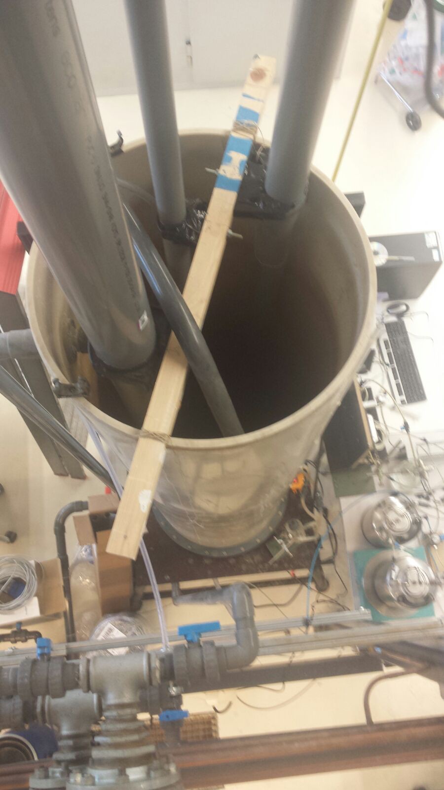
Our test setup

It is very important that the water meter stands on a weather-independent construction. For instance the electronics have to be dry all the time and it should not be blown away when wind kicks in.The data the water meter will collect needs to be saved first before sending it to a central station. The meter will not measure constantly but for instance 100 single times in five minutes. This is for energy sake. When using 100 individual measurements, the water meter should take the median of the data for the best approximation of the water level. Once per hour the water meter sends this data, using mobile network, to a central station. Once again, this is only once per hour for low energy consumption.

The energy will be provided by a solar panel. After transforming the energy of the sun into electricity, the energy will be stored in a battery which will be managed by a so-called Battery Management System.


To prevent the water meter from being stolen, all components will be hidden and locked. It only opens for maintenance reasons.

World Changing

Floods are still the cause of thousands of deaths every year. By better understanding of the water behaviour a lot of damage can be prevented. One way to prevent this is an affordable water level measuring station. It can warn people for floods, so regions can be evacuated on time.

This project can also bring economic progress, since the measurements of water depth can be used in the shipping world. If the water depth is known at all times, ships will not get stuck in low waters and loss of goods and ships can be prevented.
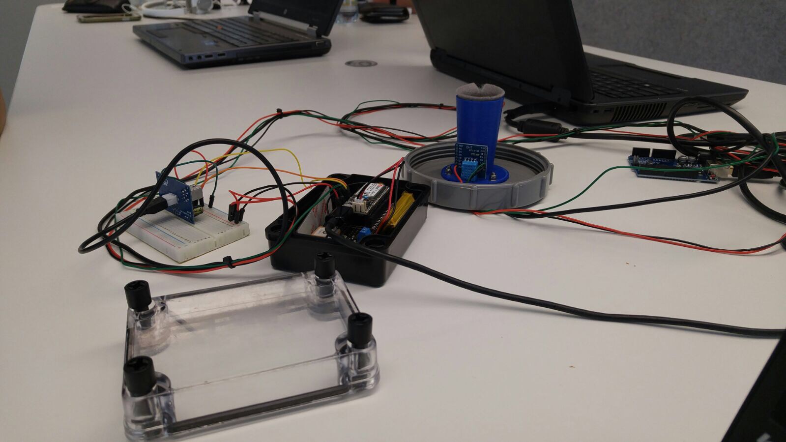
Wieltje.SLDPRT

SolidWorks drawing pulley

sldprt - 305.50 kB - 05/11/2017 at 09:41

Download

encoder holder.SLDPRT

SolidWorks drawing encoder holder

sldprt - 226.00 kB - 05/11/2017 at 09:41

Download

Tuutje 4.16 graden met flens.SLDPRT

SolidWorks drawing small funnel

sldprt - 213.50 kB - 05/11/2017 at 09:41

Download

Tuutje 4.16 graden.SLDPRT

SolidWorks drawing small funnel

sldprt - 166.00 kB - 05/11/2017 at 09:41

Download

Bevestiging infrarood.SLDPRT

SolidWorks drawing fixation infrared sensor

sldprt - 220.50 kB - 05/11/2017 at 09:41

Download

View all 7 files

  • 1 × Particle Electron Will be used to send data to the cloud
  • 1 × Arduino UNO For prototyping only
  • 1 × Temperature and humidity sensor This will be used to calibrate the speed of sound
  • 1 × Lipo Battery
  • 1 × Battery Management System

View all 8 components

  • The project continues.

    Jelle Kramer07/12/2017 at 14:29 1 comment

    It's been a while since the last update of this project. All the team members were very busy with exams, among other things. The next goal is to make the sensor work using the Particle Elektron as a microcontroller. This is quite a challenge, as there is not as much information available as for the Arduino. I will try to write as much as possible about the progress here on Hackaday and reply to all your comments and questions.

  • Ping! Internet of things!

    Maarten05/23/2017 at 13:23 0 comments

    23/05/2017

    It has been a little while since we informed you. We have been busy with several things.

    We just transferred the arduino code for the Ultrasonic sensor to Particle.io. An electron 3g is used to send the data to this platform. We faced some problems while doing this, because slightly different libraries are used in de particle firmware. Currently, we are trying to make the data a so called "variable" to request the information as a replacement of the serial monitor used in the arduino software. We still face some problems doing this, but we expect to find the solution soon.

    Besides this transferring to the cloud, Jelle did research on working principles of the sensors. To really understand what our device does, we had to get our head around how all components of the system work. The working principles of the following sensors were examined:

    1. Ultrasonic sensor
    2. Sharp Infrared sensor
    3. Laser distance sensor
    4. Radar
    5. Pressure sensor
    6. Float-operated shaft encoder

    Considering the pros and cons of the methods described above, the most suitable method for measuring a water level is the ultrasonic sensor (JSN-SR04T). The sensor is cheap and waterproof, which is a requirement in the moist working environment. Also, the measurements are accurate and have a negligible deviation. The only physical quantities that might affect the reliability of the sensor are the temperature and the humidity. Using a temperature-humidity sensor, the effect of these quantities on the speed of sound can be taken into account. At just one dollar, the temperature and humidity sensor doesn’t have a big impact on the budget. Furthermore, there are no moving parts used in this sensor and since moving parts require more regular maintenance, this is an extra reason to use the ultrasonic sensor.

    Meanwhile, Maarten did research on the ethical perspective of the project. Will our project actually contribute in making a step forward in the development of a country like for instance Myanmar? For safety-reasons, one could immediately say that this will be a step forward. But other factors also influence the development. This is what our ethical research is about. We are working on an essay, which we will post when it is finished.

  • Open Log

    Maarten05/15/2017 at 10:51 0 comments

    15/05/2017

    During the weekend, one of our team members was working on changing the configuration of an Open Log. The data provided by the sensor usually comes in on the serial monitor. Using the Open Log the data will automatically be saved as a .txt file on a SD card. In the future we will configure the Particle Electron to save it's collected data on an SD card and send it to a cloud server as well.

    To be continued...

  • Absorbent material and temperature influences

    Maarten05/15/2017 at 10:28 0 comments

    15/05/2017

    Last Friday we tried three different types of sound absorbent materials. The first one is plastic foam. We placed a bunch of foam at the small funnel and tested the sensor. Until 2.5m everything went well, but at larger distances the foam does not absorb enough. But, the combination of plastic foam with the big funnel worked excellent.

    Nevertheless we would like to use as less material as possible, so we tried a second material, which was craft foam. This did not work at all. So we immediately tried a third one: felt. This turned out be the best material for our purposes. The size of the funnel does not matter. However, the possibility of accretion is a big disadvantage.
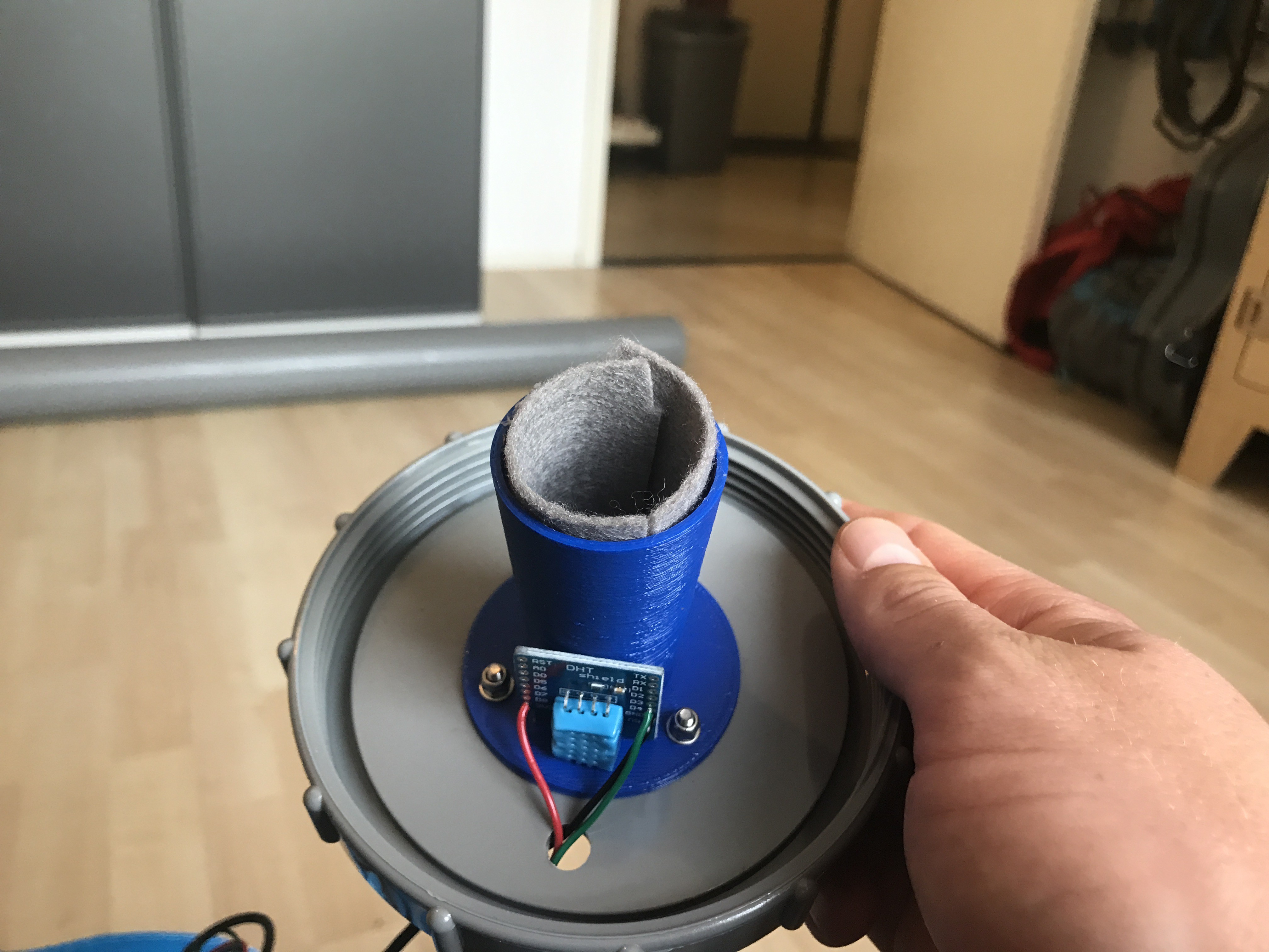
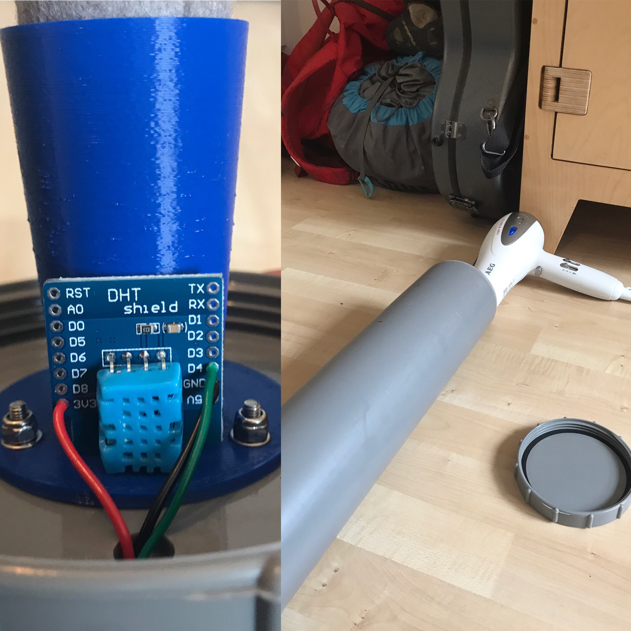
    After looking for the right absorbent material, we tested the influence of a temperature gradient to the sensor. We used a hairdryer to warm up the air inside the pipe. As we expected, when the temperature rose, the measured distance was smaller than it should be. This is because of the higher speed of sound at higher temperature. In order to eliminate this error we added a temperature and humidity sensor. We are now trying to write a code which implement the data of the temperature/humidity sensor into the distance measurement to tackle the temperature problem.

  • Finally got the ultrasonic sensor working

    Maarten05/09/2017 at 14:51 0 comments

    09/05/2017

    First we want to thank the Hackaday jury members for selecting us as one of the twenty winners of the first round of the Hackaday Prize 2017. This is a great motivation and we will continue to work hard on this interesting project.


    In addition to this good news, we finally found a solution to the problems we faced with the ultrasonic sensors.

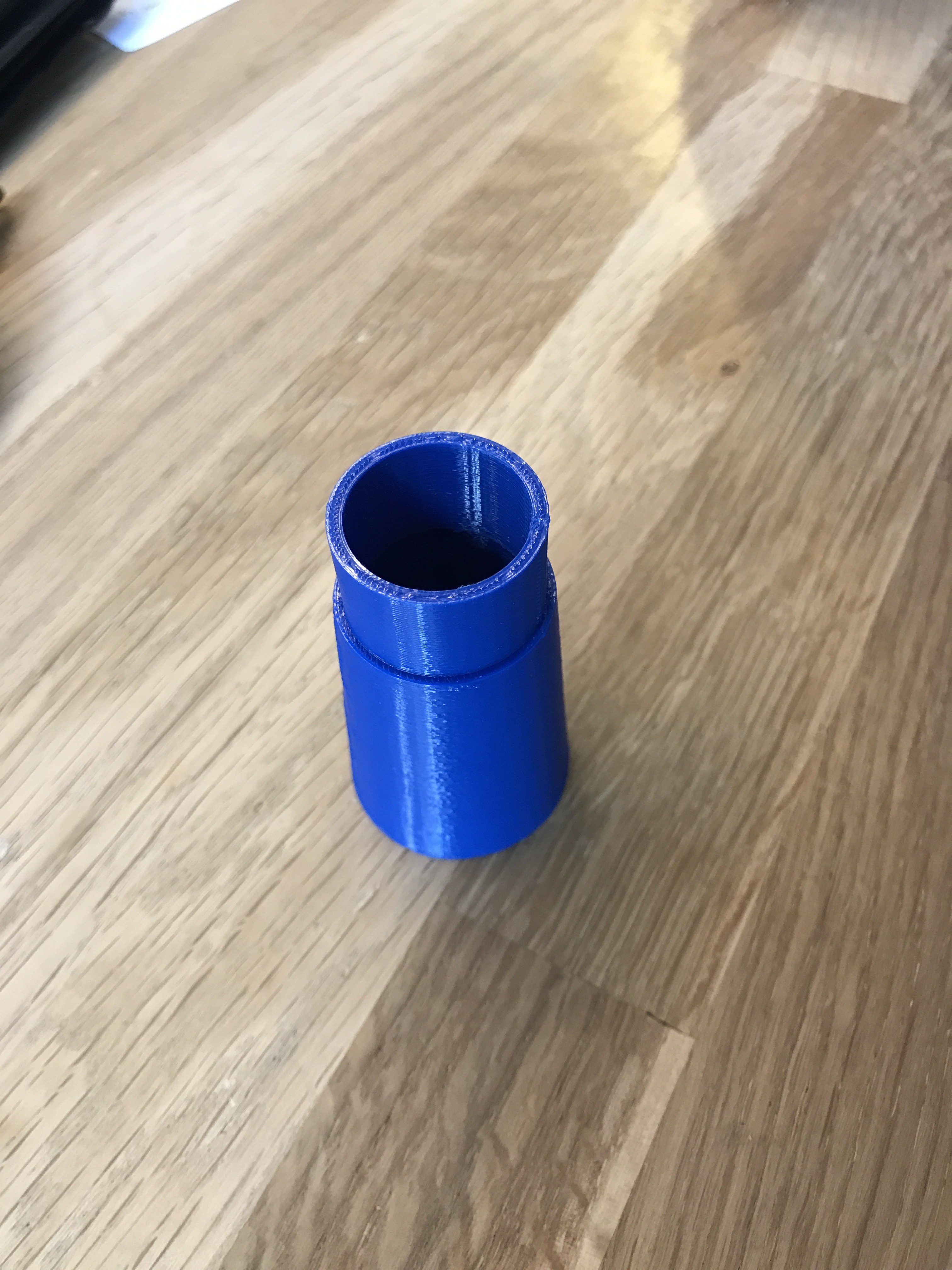
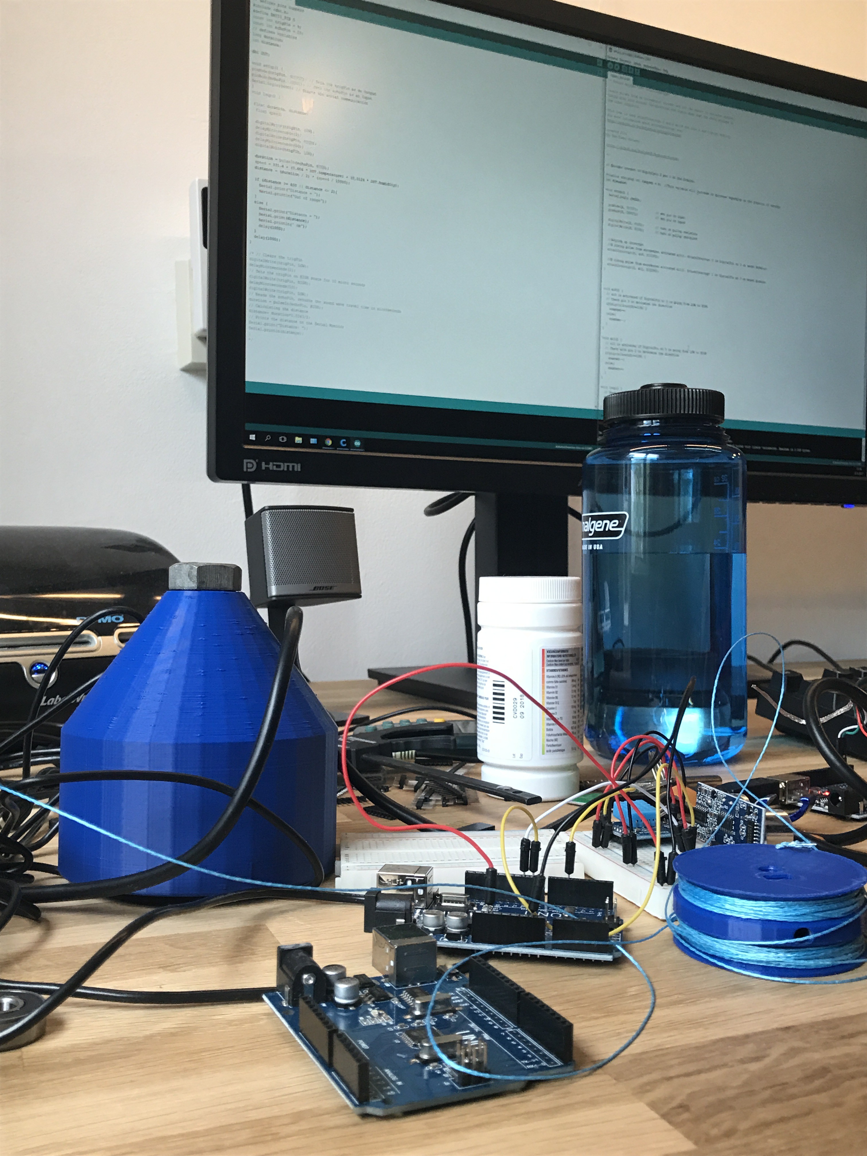
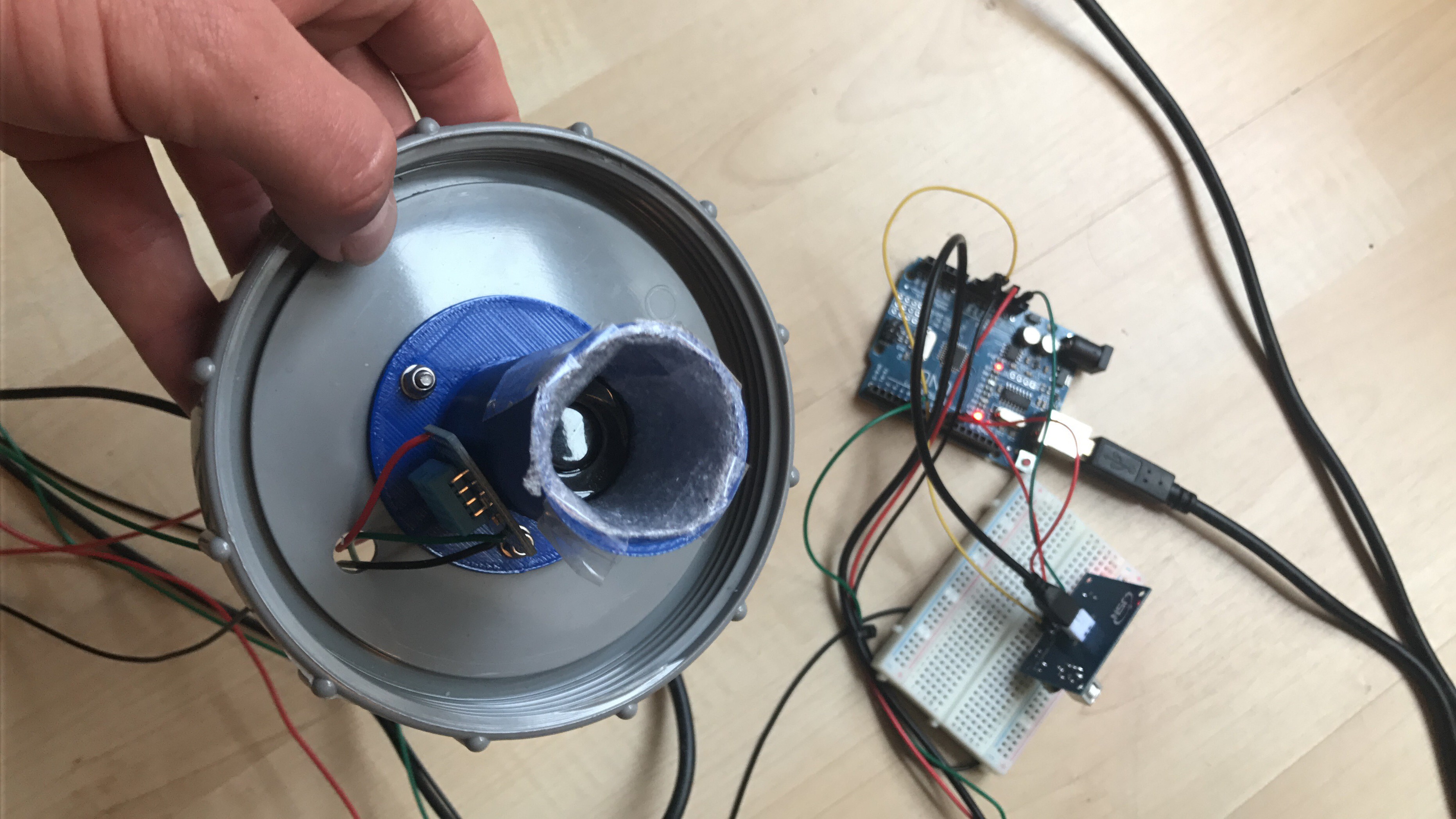
    We already made a funnel, with a wide diameter, but this turned out to be insufficient. In order to fix this we first made a funnel with a smaller diameter (see figure), but this did not have the desired effect as well. The walls of the funnels reflected the ultrasonic waves immediately, so a decent water level measurement could not be made.

    Funnel with smaller diameter

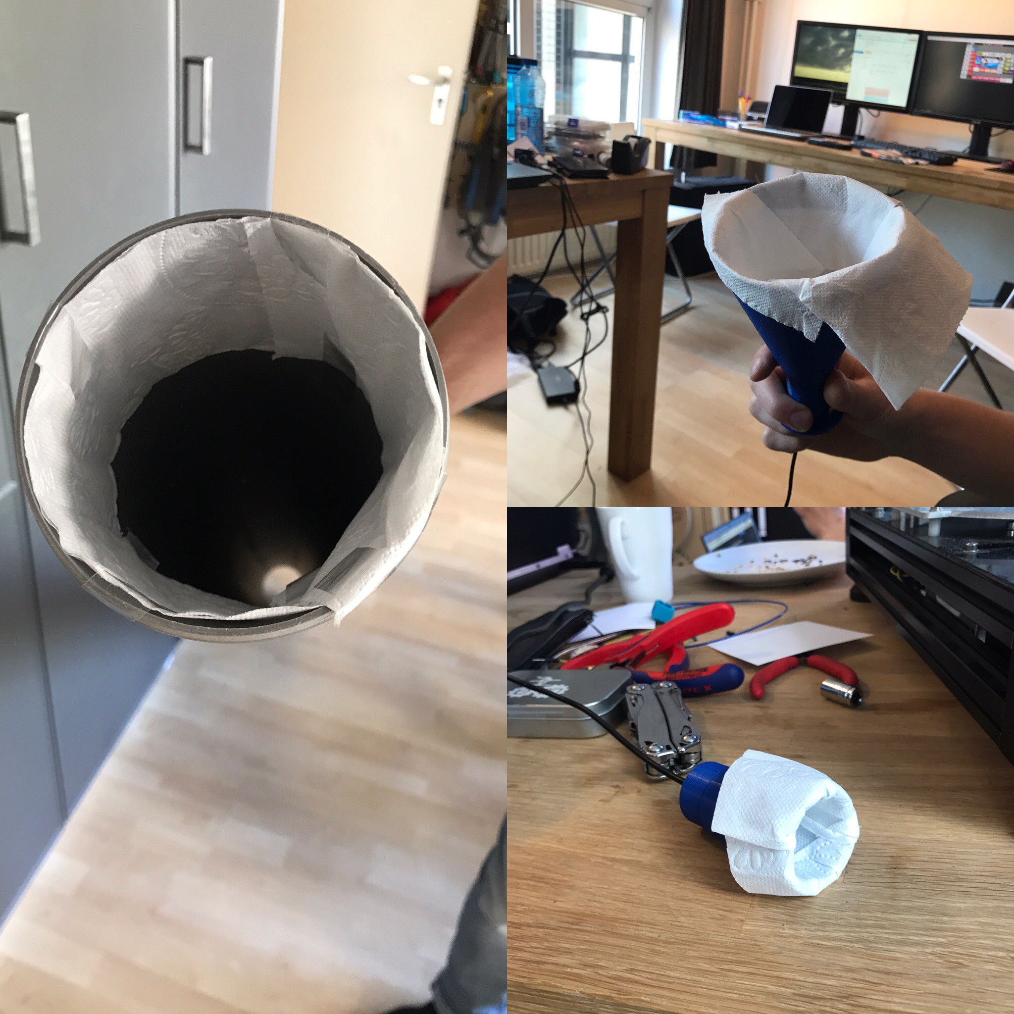
    We thought that the material of the 3D-printed instruments did not absorb the waves enough, which caused the too low values. Therefore we needed a sound absorbent material. The first thing that came in mind to test this was toilet paper. So we pasted some toilet paper on the walls of the funnels. Against all our expectations, this worked perfectly. In the video, one can see the results of the measurement, while the water level was increasing.

    Besides the placement of toilet paper on the funnels, we also tried to place some toilet paper on the walls at the top of the pipe and use the sensor without any funnel. This turned out to work perfectly as well. Economically speaking this has even more advantages. It will be cheaper to place only an adsorbent material at the top of the pipe than produce a funnel ánd place an adsorbent material.

    From now on we will look to find a more durable adsorbent material to place at the top of the pipe.

  • Test sessions

    Maarten05/08/2017 at 13:25 0 comments

    03/05/2017 - 08/05/2017

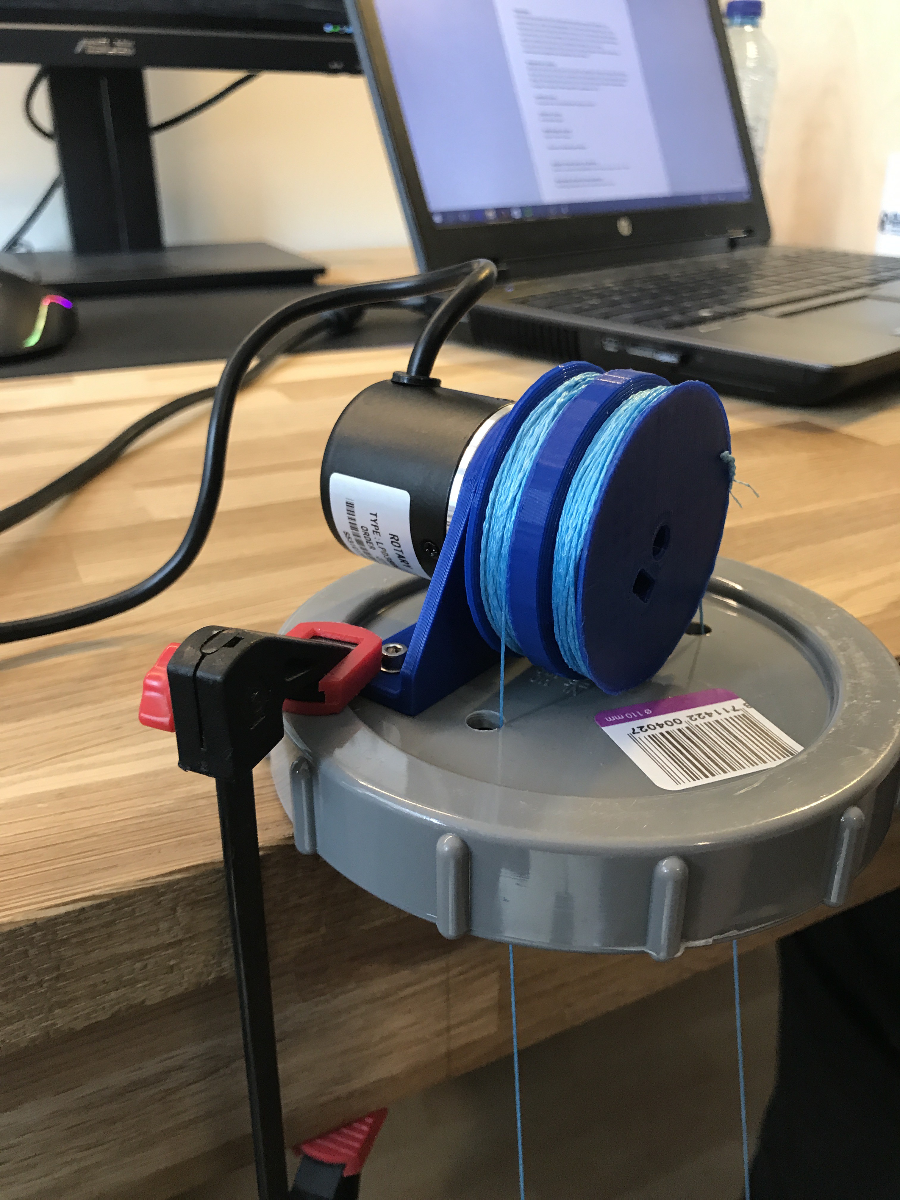
    Wednesday the third of May we joined the laboratory tour, which was mandatory before doing our experiments. After the tour we immediately began testing, starting with the encoder. This method worked out very well. The values given by the sensor matched perfectly with the real water level values. Just small errors occur, since the diameter of the pulley changes when the water level changes.

    We also tested the non-waterproof ultrasonic sensor. Unfortunately this sensor had some trouble with a small notch in the beginning of the pipe. The ultrasonic waves were bounced back immediately by the notch, and not by the water surface. In order to fix this error we pasted some tape over this notch, to make the pipe surface smooth. This did not have the desired effect.

    On Thursday we went on trying to fix the problems of the non-waterproof ultrasonic sensor, as well as starting with the waterproof ultrasonic sensor. Also on this day, an infrared distance sensor was made available by the University.

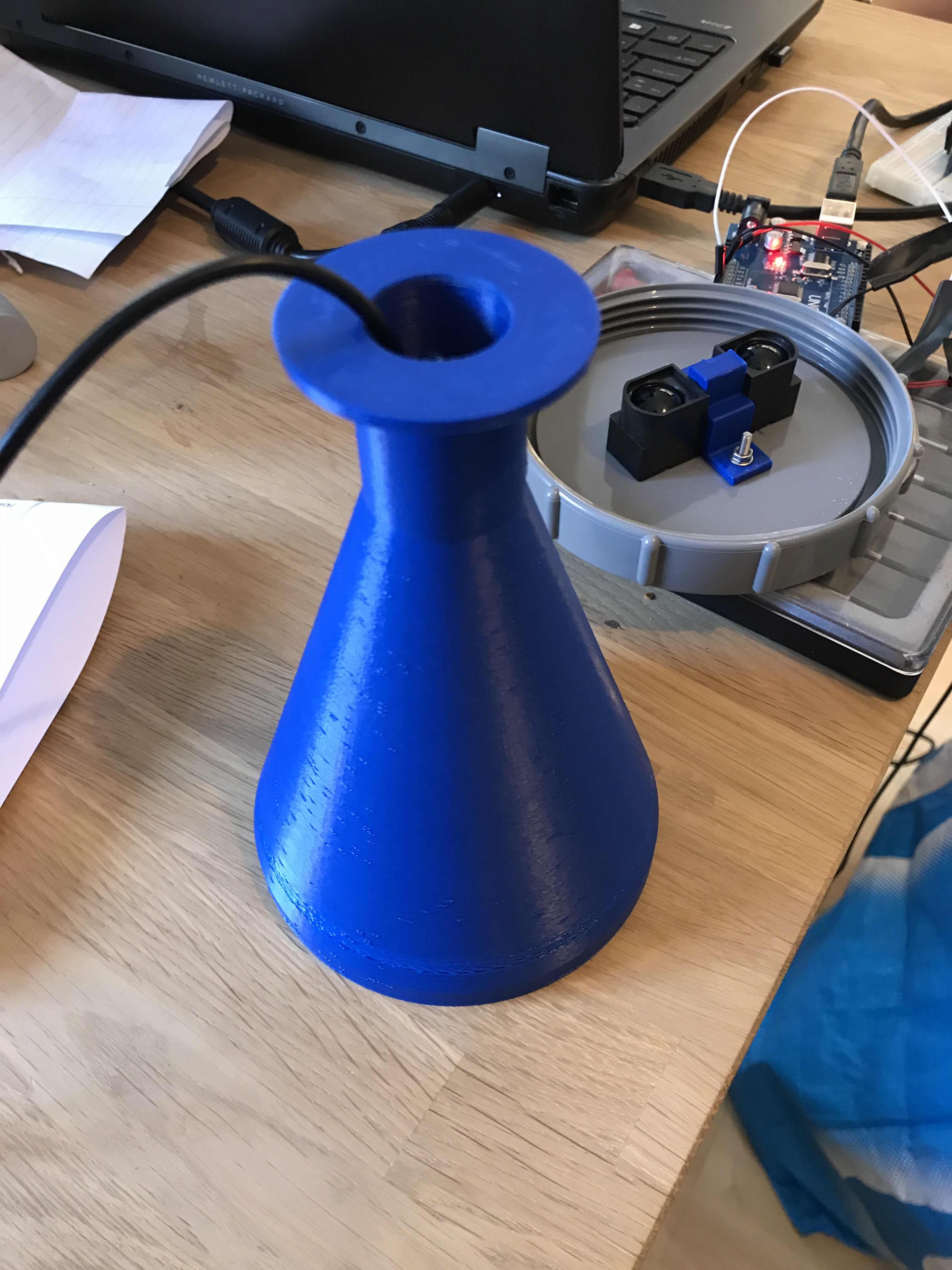
    In order to make the ultrasonic sensors work, we designed a funnel, so that the notch is skipped. For the IR sensor we designed a bearer, which should help the fixation to the pipe.

    Funnel with the waterproof ultrasonic sensor & IR sensor fixed with bearer

    On Monday we first started by testing the IR sensor. The respons was good, but the values fluctuate in a range of 10 centimeters. The ultrasonic sensors still didn't work, despite the funnel.

    We are now discussing how we should make the ultrasonic working. We consider to get some help from experts of the University.

  • Preparing experiments

    Maarten05/02/2017 at 10:30 0 comments

    02/05/2017

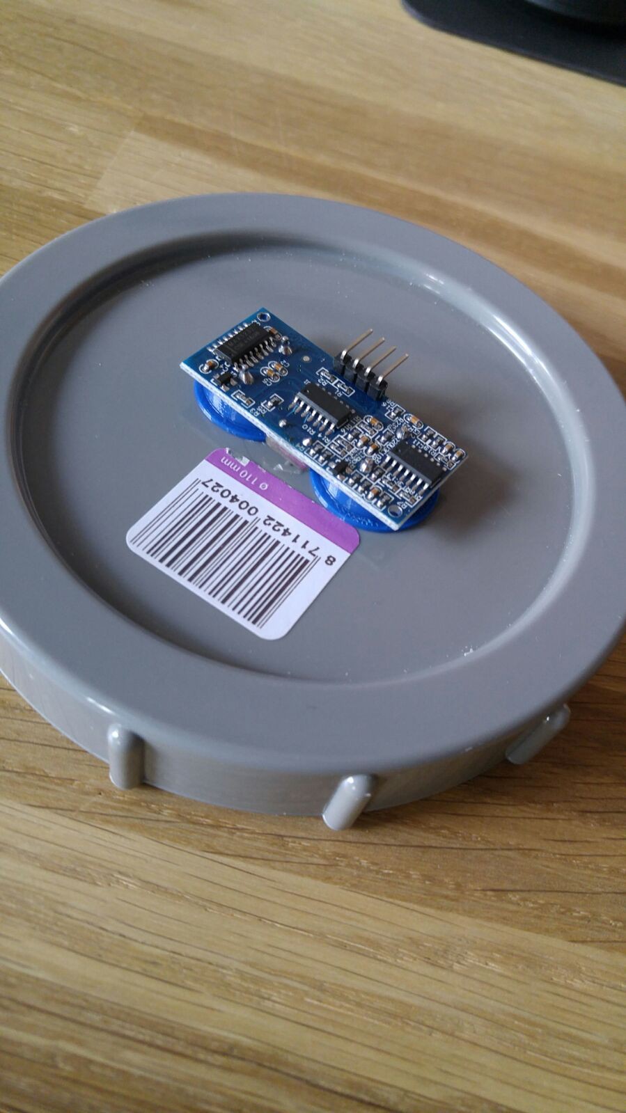
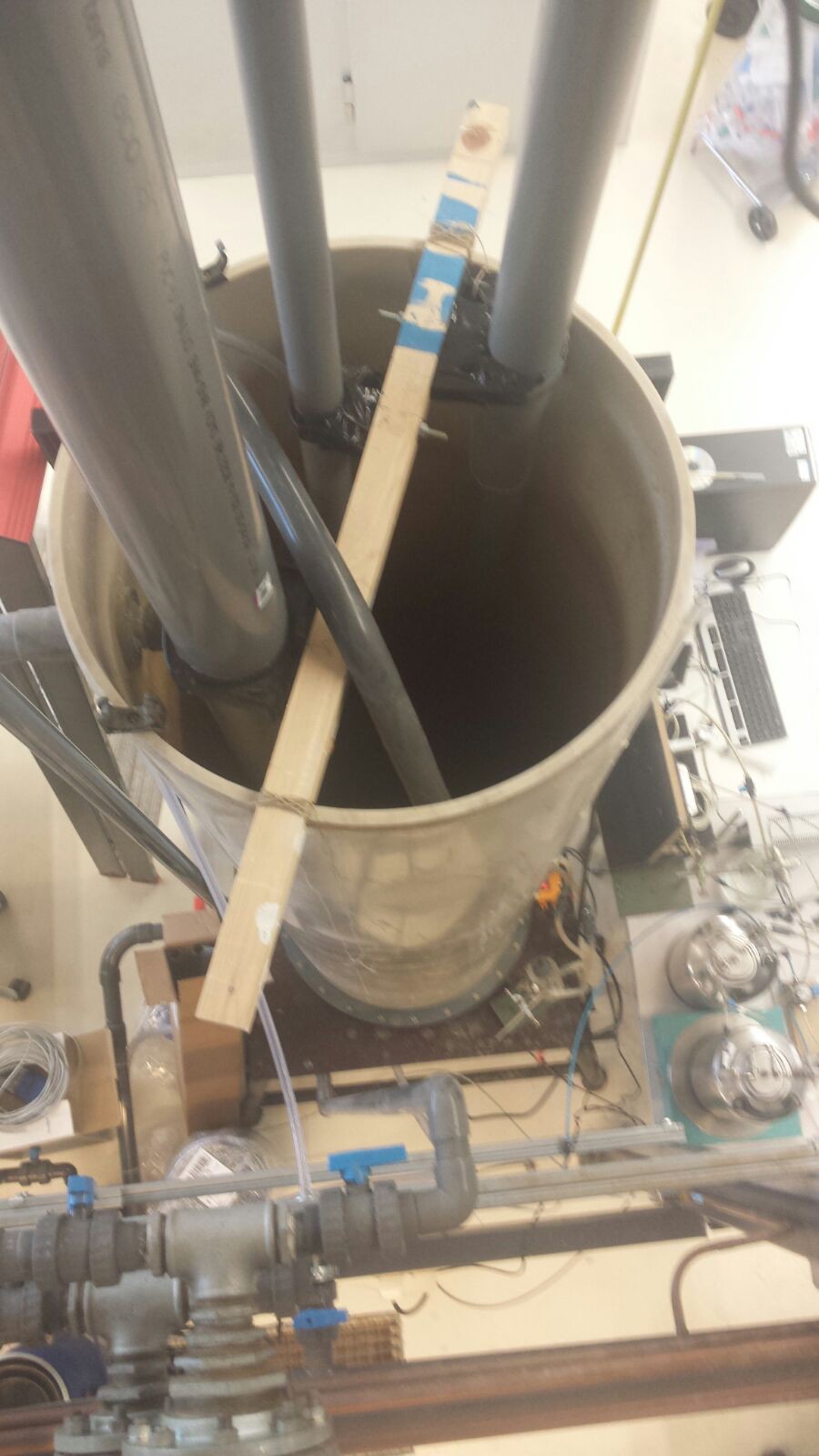
    As the test setup present in the laboratory was not suitable for our experiments yet, it needed some modifications. The tubes did fit threaded caps, so six of these were purchased to attach the different sensors to. This will make sensor placement and removal easy. An extra advantage of using these caps is that they close off the tubes and thus the conditions in the tube (e.g. temperature, humidity) can be varied.
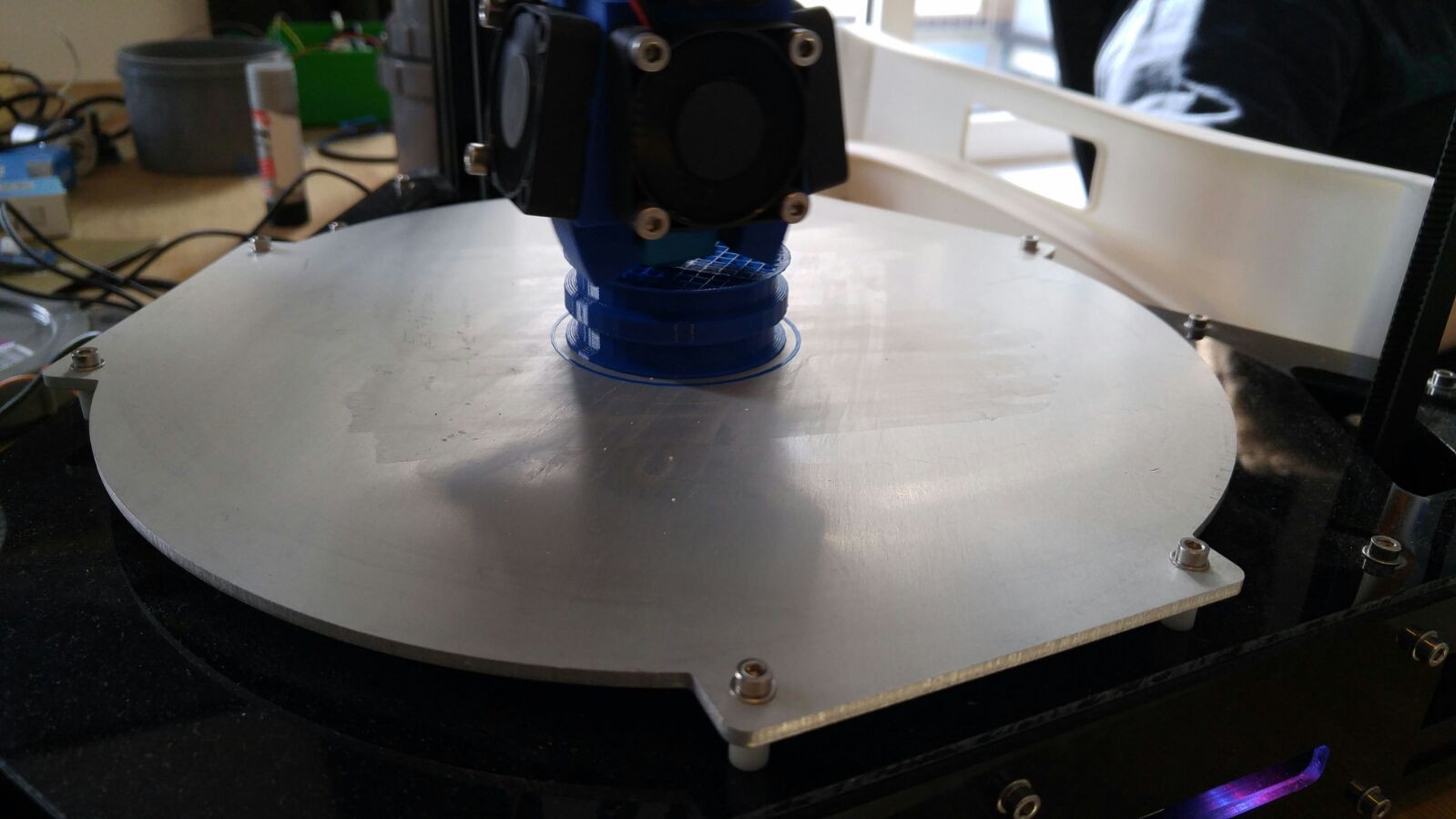
    The caps had to be modified to fit the sensors. Holes were drilled to attach the ultrasonic sensors and an adapter was 3D-printed for one of them. To fix the encoder on a cap, an encoder base is designed and printed.

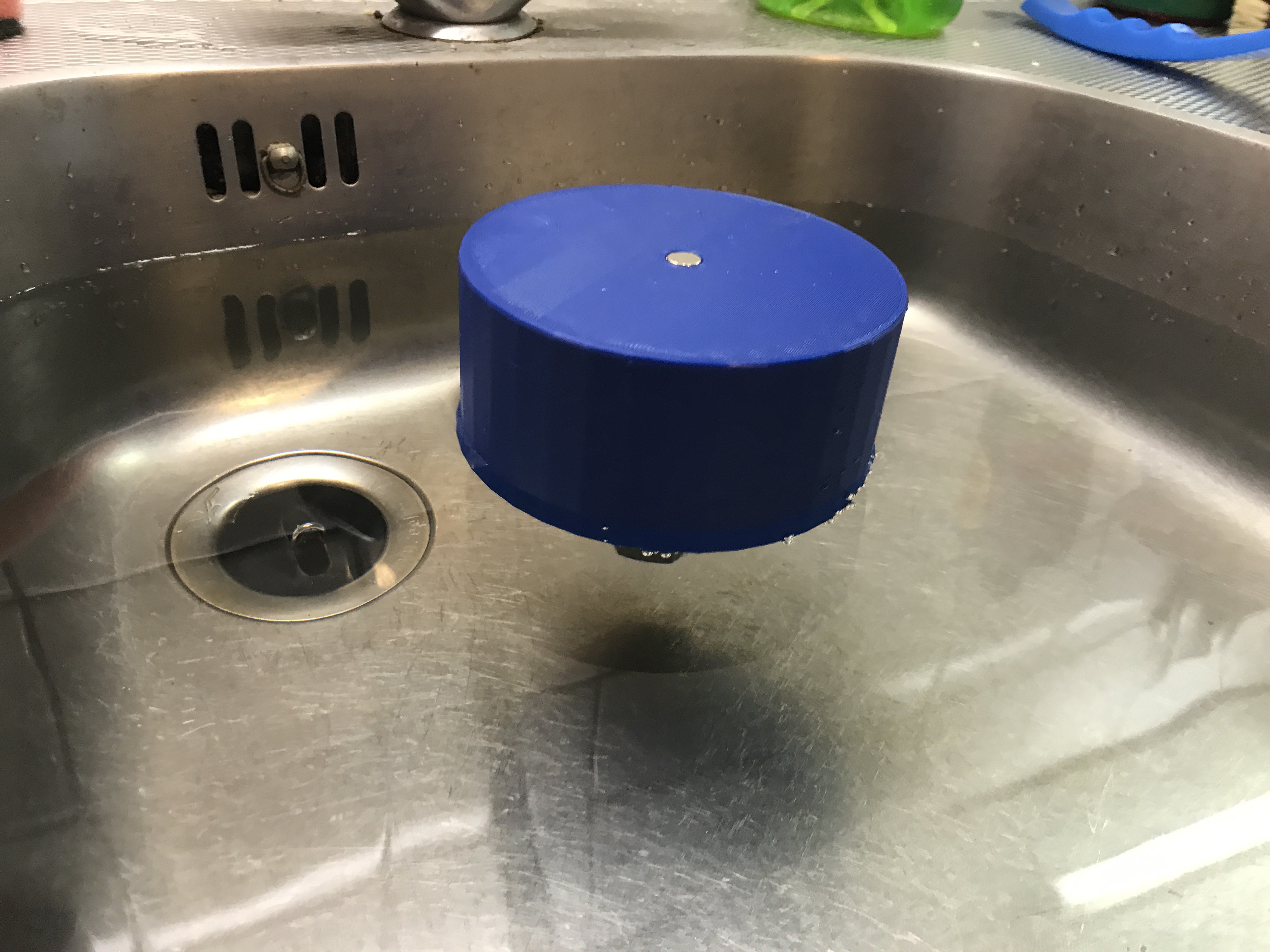
    The method with a float, of course needs a float. So this measure instrument is designed and printed too.

    After producing and assembling all the test equipment, programming starts. All methods are programmed and temperature and humidity influences are taken into account, except for the waterproof ultrasonic sensor. So when this code is written, all experiments are well-prepared in order to pick the best measuring method.

    Tomorrow (Wednesday the 3rd of May) we will have a tour through the laboratory and hopefully we can start with some of the experiments
  • Preparing for sensor selection

    Benne04/30/2017 at 14:04 0 comments

    28/04/2016 In order to determine the best measuring method for water levels, we went through the following proces. First we looked at all the different options that are out there. Water levels can be measured with: pressure sensors, ultrasonic sensors, radar, laser, float with pulley and encoder, variable resistor, camera's and sattelite imaging. In order to find the most affordable, accurate and reliable sensor, we made an initial selection based on price, specs and availability. Next we ordered a bunch of different sensors, that came out as good options.

    In order to test the performance of these sensors, we have prepared a test setup based on a tube in which the water level and temperature can be altered.

    We have prepared a bunch of different holders for the sensors we would like to test and we have written some code, which will allow us to analyze the sensor performance. The code can be found in the dropbox folder.

    Next week we will test the sensors and hopefully select the best candidate, so we can start designing our first prototype.

View all 8 project logs

Enjoy this project?

Share

Discussions

nodemcu12ecanada wrote 05/28/2020 at 18:21 point

A $4 NodeMCU can send data to a cloud spreadsheet or to an online graph via MQTT.

https://sites.google.com/site/nodemcu12e/

  Are you sure? yes | no

Edoardo wrote 12/16/2017 at 12:12 point

Hi, really cool project! I had a look to "Tuutje 4.16 graden met flens.SLDPRT" and it seems to me that it's non-dimensional. Can you please tell me de diameter of the base? Many thanks for your help!

  Are you sure? yes | no

Tindie wrote 06/23/2017 at 00:23 point

Congratulations on being one of the Internet of Useful Things Hackaday Prize Finalists!

  Are you sure? yes | no

Jelle Kramer wrote 07/12/2017 at 14:32 point

Thank you! This motivates us to just go on!

  Are you sure? yes | no

Giovanni wrote 06/20/2017 at 23:33 point

Hmm, solving 3rd world problems with technology... Good luck with that ;)

It may be a nice play-project but think about the wider challenges you're going to face:

- Reliable and cheap cloud connectivity from Bangladesh rural areas. Wifi? Unlikely. 3G? Unlikely. LoRa? Unlikely. What's the plan then?

- Alerting infrastructure - good to know that a flood is coming but then what? Alert a central / local government? And they do what? Same as now I guess, i.e. nothing. Western-style civil defence systems are largely non-existent in these countries, especially in rural areas. Even a simple siren on a pole may be too much to ask, let alone kicking off a coordinated evacuation effort when your stations _suspect_ a flood is coming. 

And we haven't even touched the logistics of installing and maintaining the sensors. 

Good luck changing the world but I'm afraid technology won't do it. You'll have to make the governments care to support and protect their people first to change the world. But that's well beyond the scope of hackaday...

  Are you sure? yes | no

Jelle Kramer wrote 07/12/2017 at 15:23 point

Thank you for your reply.  I agree that Wifi is not likely to be used to transfer the data. However, during a short research we discovered that the 2G/3G coverage in 3rd world countries is sufficient in most areas.

As for the alerting infrastructure, we are aware of the fact that monitoring water levels alone won't warn people for upcoming danger.  This infrastructure is also an important subject that needs research, before a total solution can be implemented. 

For now, we are focussing on the technological part, which we think is a very important one. Once again, thank you for your input and I hope you keep following this project!

  Are you sure? yes | no

David Stacer wrote 05/08/2017 at 18:06 point

I built a sump pump flood alarm and to measure the water level, I used two BMP280 pressure sensors.  On inside a PVC tube where the top was closed and one outside the tube to measure atmospheric pressure.  Calculate the difference in pressure and use pressure head calculations to find the water level.  Accurate to 1 cm in my testing.  

  Are you sure? yes | no

Florian Festi wrote 05/08/2017 at 19:18 point

Well, that assumes that the tube is (basically) completely filled with air. If the air leaks out or gets resolved in the water the sensor gets out of  calibration. If you regularly drop the water level below the measuring pipe that's not an issue. But for continuous measurements it is.

  Are you sure? yes | no

Martijn wrote 05/09/2017 at 08:47 point

Thanks for your reply. The most important factor for us for not using the pressure sensors, is the variation in temperature. When the temperature rises, the pressure will increase too. And because our design is ment to be implemented in warm countries, the pressure difference will affect the measurements drastically.

  Are you sure? yes | no

David Stacer wrote 05/09/2017 at 10:57 point

The BMP280 does have internal temperature compensation to adjust pressure readings based on current temperature.  In my application the temperature is mostly constant.  You would need to test a wide range of temperatures for your application.

  Are you sure? yes | no

Marian Keller wrote 05/01/2017 at 10:48 point

You should also try capacitive water level sensing.

See: http://www.ti.com/lit/ug/tidu736a/tidu736a.pdf

  Are you sure? yes | no

Ingmar Guillaume wrote 05/01/2017 at 00:38 point

Interested in the outcome of your setup.
I made something similar for my rain water reservoir based on the Maxbotix sensors (the IP67 ones). I measure the distance to the water level in the tube, and from that calculate the remaining water content.
My "computing unit" is an electric Imp, waking up and measuring once every hour for 3 seconds, then going to sleep for the remaing 59 minutes and 57 seconds. Results are transmitted over WiFi via my home router to Xively.
With that setup, battery life with a a 10Ah LiPo pack is about a year and some (and probably longer).

  Are you sure? yes | no

Martijn wrote 05/08/2017 at 20:24 point

The problems we face with the two different types of ultrasonic sensors, is that both sensors measure a distance which is not reliable, it is way too short. We think it has to do with the reflection of sound waves via the wall of the pipe. Even with the 3D-printed cone problems still occur. What was the diameter of your tube?

  Are you sure? yes | no

Ingmar Guillaume wrote 05/08/2017 at 20:57 point

I should open the water reservoir, but I estimate it was something around 3m long and 10 cm diameter. The sensor I selected was one with a narrow beam. Again, I should open it to verify the number, but I remember it was with a horn.


I did make a few holes at the top to let the waterlevel rise. Otherwise you have a closed tube which does not let water run in.

While trying to figure out which sensor I used, I came across this document on the Maxbotix website: https://www.maxbotix.com/articles/124.htm, which specifically deals with the use of these sensors in a pipe. That wasn't on the website when I build the system.

The main problem I have is the battery I use. I have a 3-set of NiMH delivering barely enough voltage at 3.6 V. The power is largely sufficient, but the supply voltage is too close to the limit to make the thing last for longer than 6 weeks. I have tried inserting a LiPo battery pack, but unfortunately all the ones I have are just that little bit too large to fit in the housing of the electronics (the sensor is in the tube inside the well and cable connected to a waterproof housing through a mil spec connector outside of the well.)

I use a FET triggered from one of the IMP's digital pins to power up the sensor, I wait for 250 ms for the sensor to stabilize, then I read the analog output, and I compare that to the measured supply voltage. That in turn gives me the distance reading. Then I turn off the sensor (through the FET) and let the IMP go to sleep for an hour.


  Are you sure? yes | no

Martijn wrote 05/09/2017 at 08:34 point

Thanks for sharing. It makes sense, the sensor we are using is used in car parking sensors. For this application, a wide beam is needed, so not usefull in our situation. At the moment, we are looking if we can produce some housings, to make the ultrasonic beam narrower.

  Are you sure? yes | no

Ingmar Guillaume wrote 05/09/2017 at 09:31 point

Interested in your follow up. Good luck.

  Are you sure? yes | no

Similar Projects

Does this project spark your interest?

Become a member to follow this project and never miss any updates