dbtayl
-
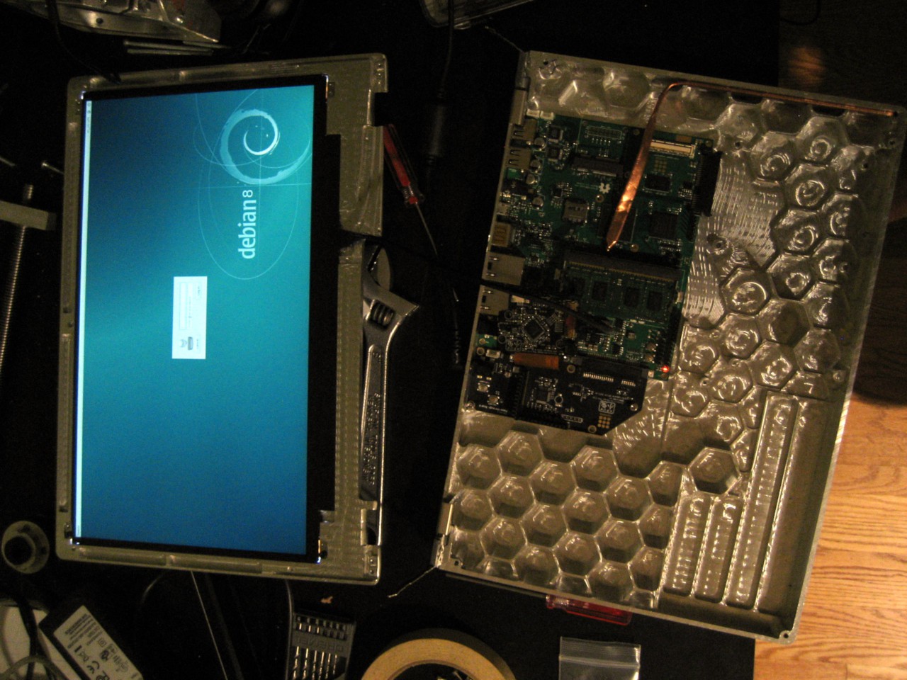
It's alive!
06/22/2017 at 03:11 • 0 commentsKinda. It turns out I slightly mis-estimated the length of the display cable, so it doesn't quite reach. Grr... Not sure how I'll fix that yet.
But the heatpipe is bent correctly-ish, and things fit together. It's a start.
![]()
![]()
-
Mostly just pictures
06/20/2017 at 03:03 • 0 commentsA fair amount of progress today, most of it not readily visible. I got holes tapped to hold the keyboard in place, as well as the LCD and hinges. I also did some fitting on the hinges, so now there's actually clearance for them to pivot. With the two bottom pieces screwed together, it feels nice and sturdy.
Still not quite enough to put the thing together- I need to run a ballnose endmill across the back edge to create clearance for the lid to pivot through the base, machine a couple pockets for the hinge screws to protrude into, and generally tap some more holes. That's on the docket for tomorrow, along with maybe cutting a power button.
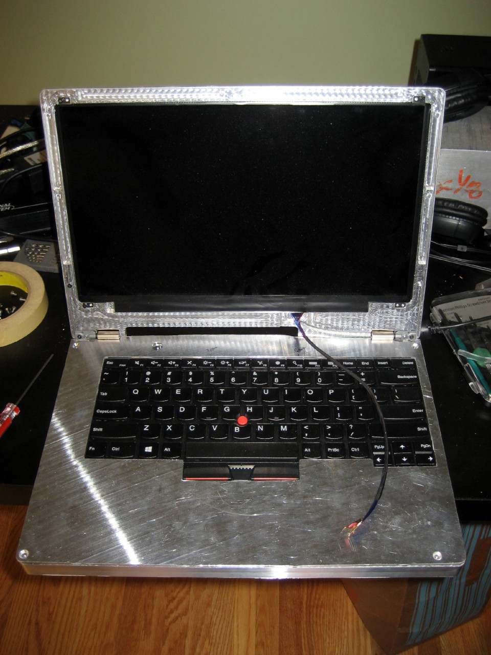
That said... pictures! I didn't put the LCD in, since it's delicate and the less I handle it the better.
Starting to look like a laptop, if you ignore the lack of certain key aspects, like a screen...
![]()
![]()
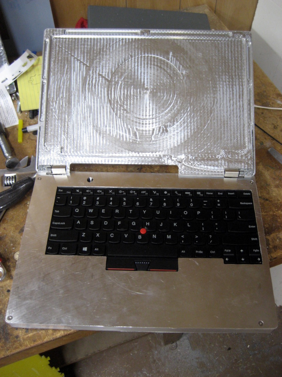
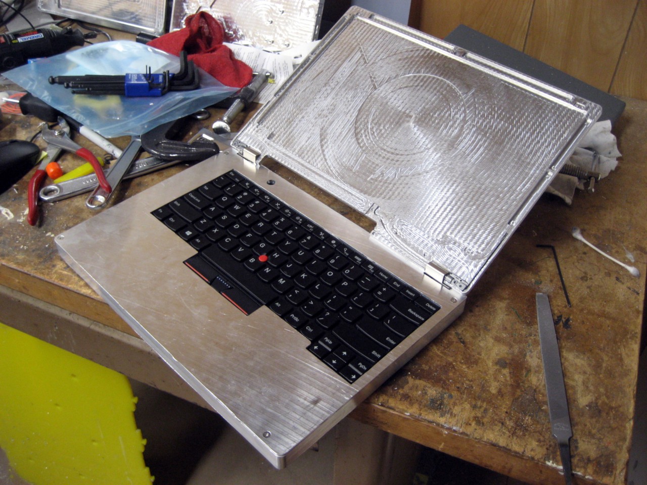
Things mostly fit together! That always amazes me... There WAS fitting involved, but still.
![]()
![]()
-
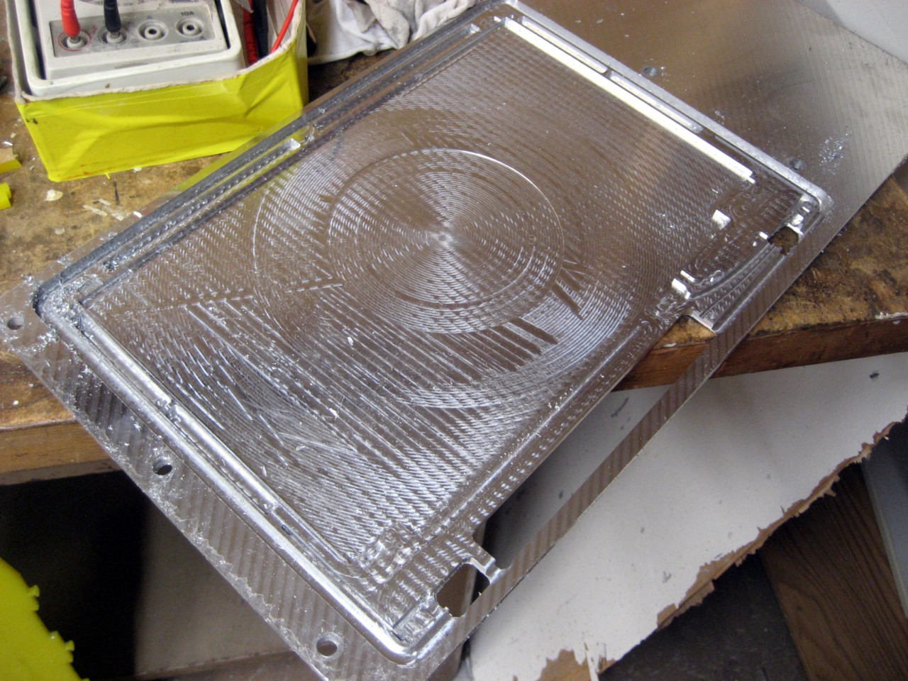
Recutting the lid
06/19/2017 at 03:51 • 0 commentsI made a small mistake on the first attempt at machining the lid. Due to a quirk of CAM, it cut ~2mm more material out of the bottom edge of the lid than intended. I was going to just call it good, but then I also realized that the lid was heavier than the hinges were originally designed for. Between those two things, I decided to recut it, with a few changes.
Those changes are mostly skeletonizing the piece to remove excess weight. I added some deep rectantular pockets around the edges, and a shallow circular pocket behind the LCD. I don't recall the exact numbers, but I want to say it cut ~10% off the weight. That's not huge, but over half of the reduction was along the top edge, where it matters most.
I assume people don't look at these posts for the text, so here are the pictures.
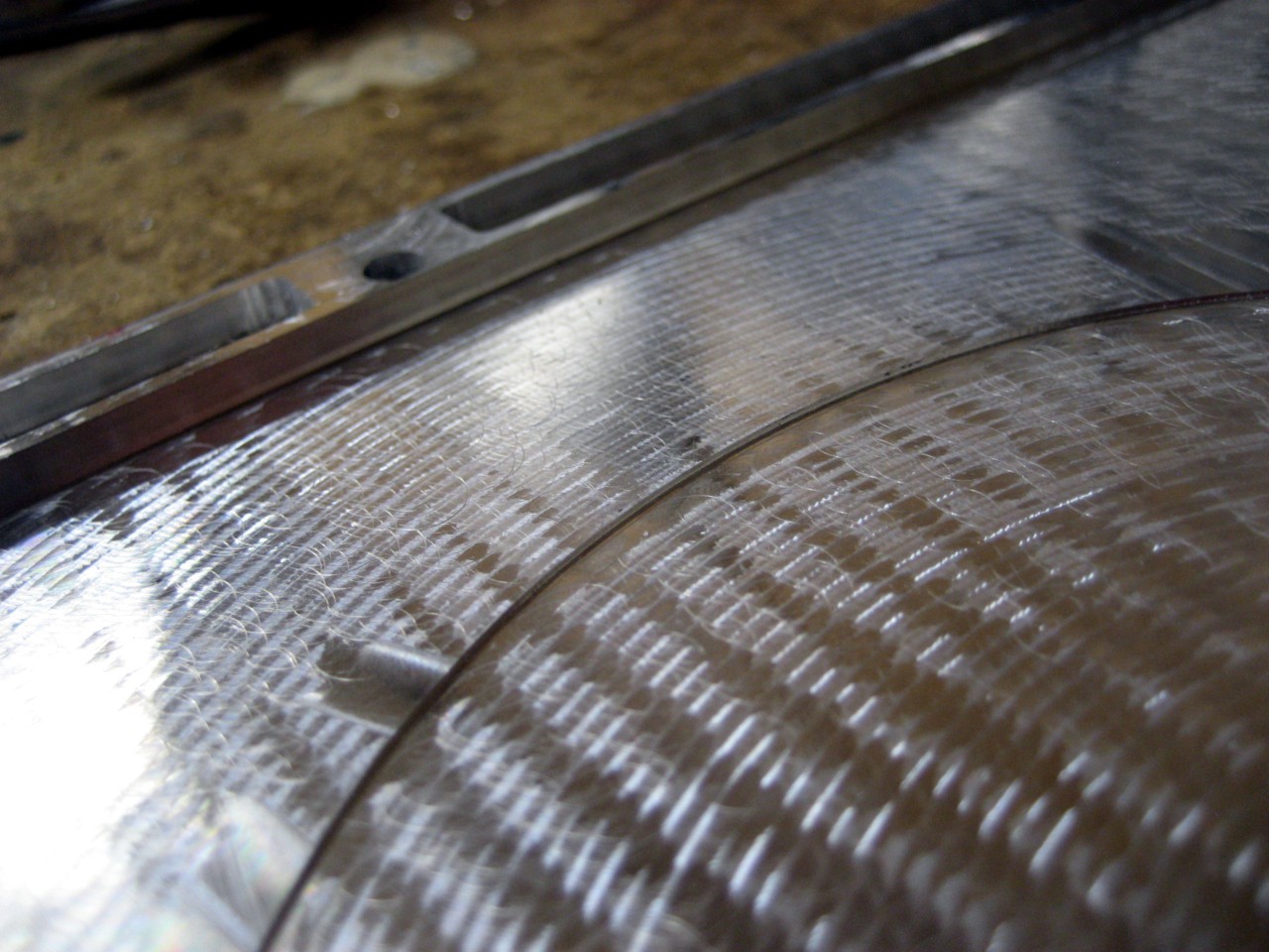
After cutting, not yet removed from the stock:
![]()
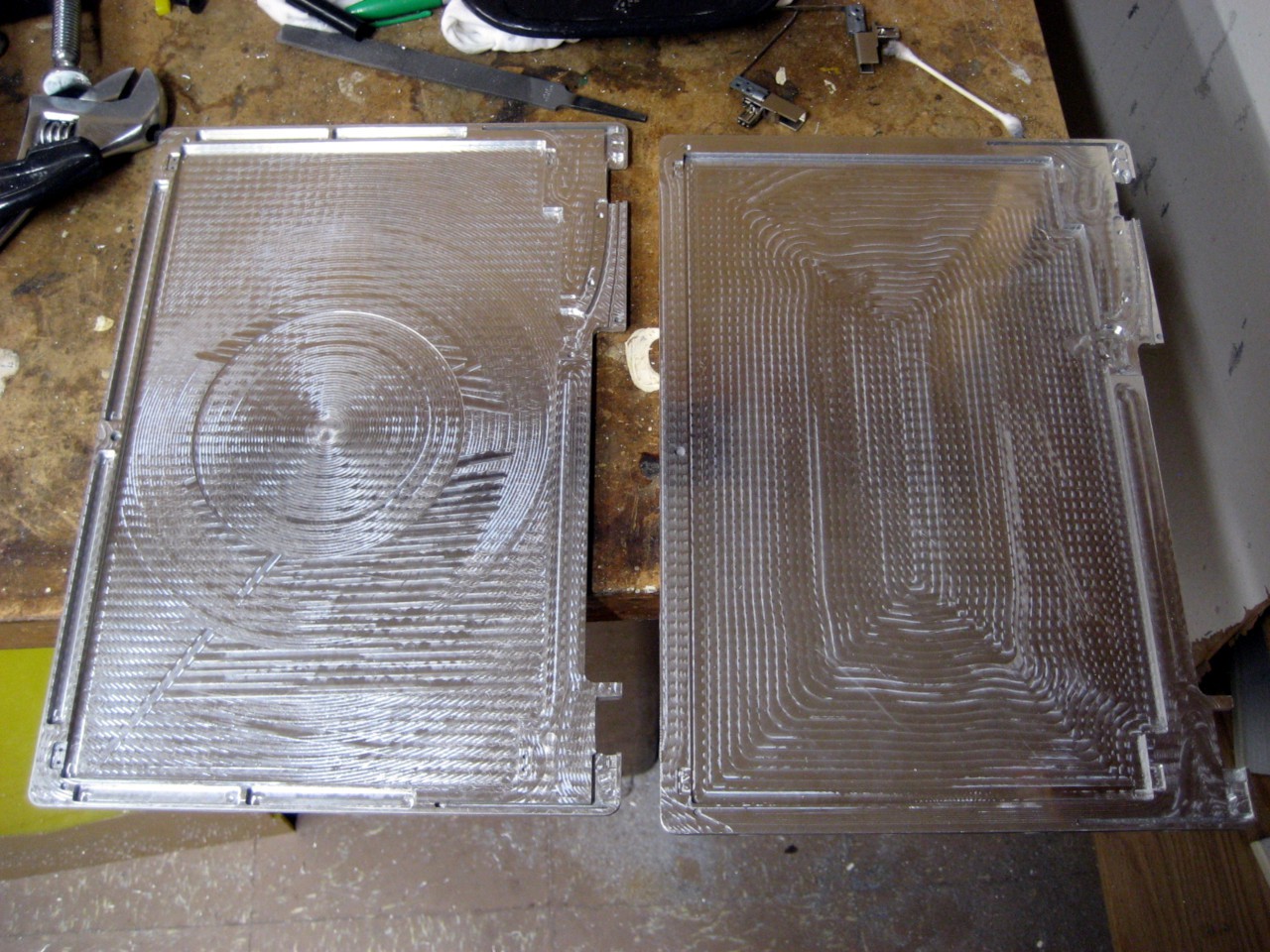
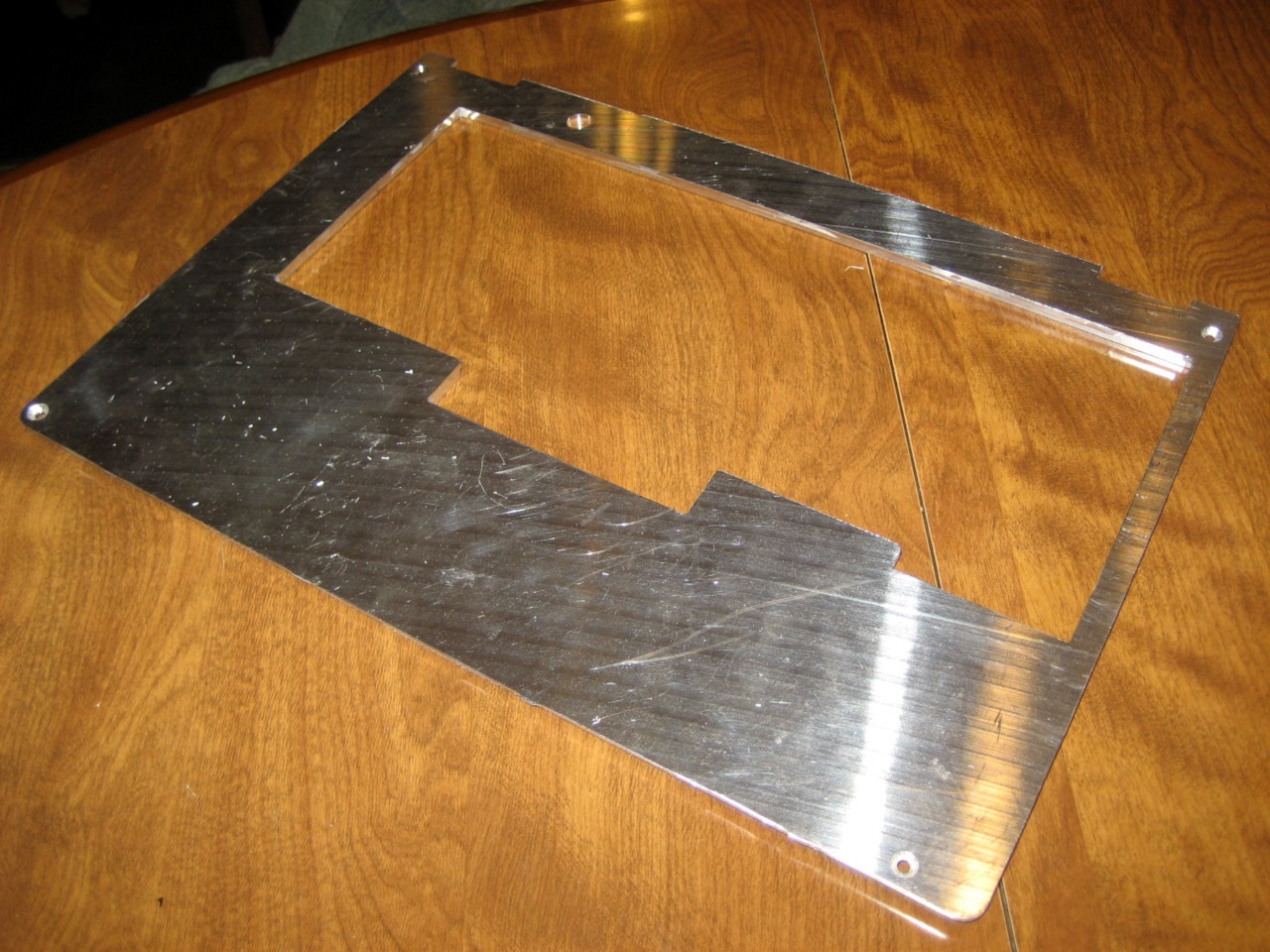
Cut out from the stock, compared to the previous attempt.
![]()
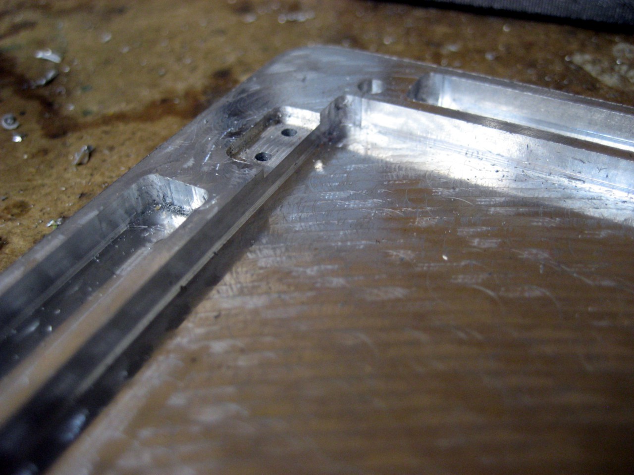
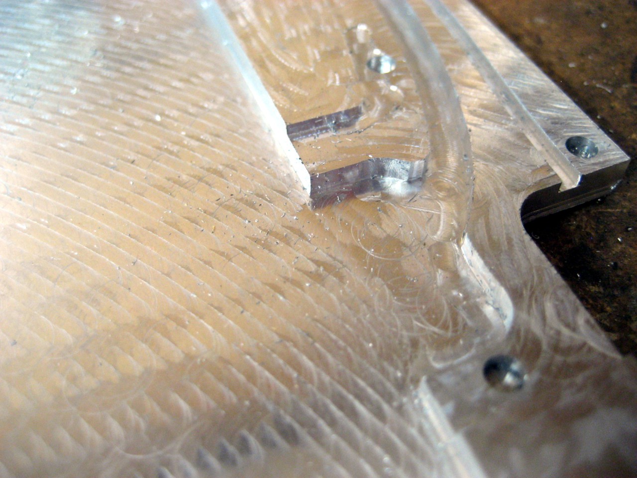
A couple detail shots of the skeletonizations:
![]()
![]()
And a couple more pictures, because why not:
![]()
![]()
Obviously it still needs some holes drilled, all of them tapped, and some other fitting, but it's looking good! I'm semi-obligated to have it semi-assembled by Thursday, so hopefully there will be some big updates coming soon!
-
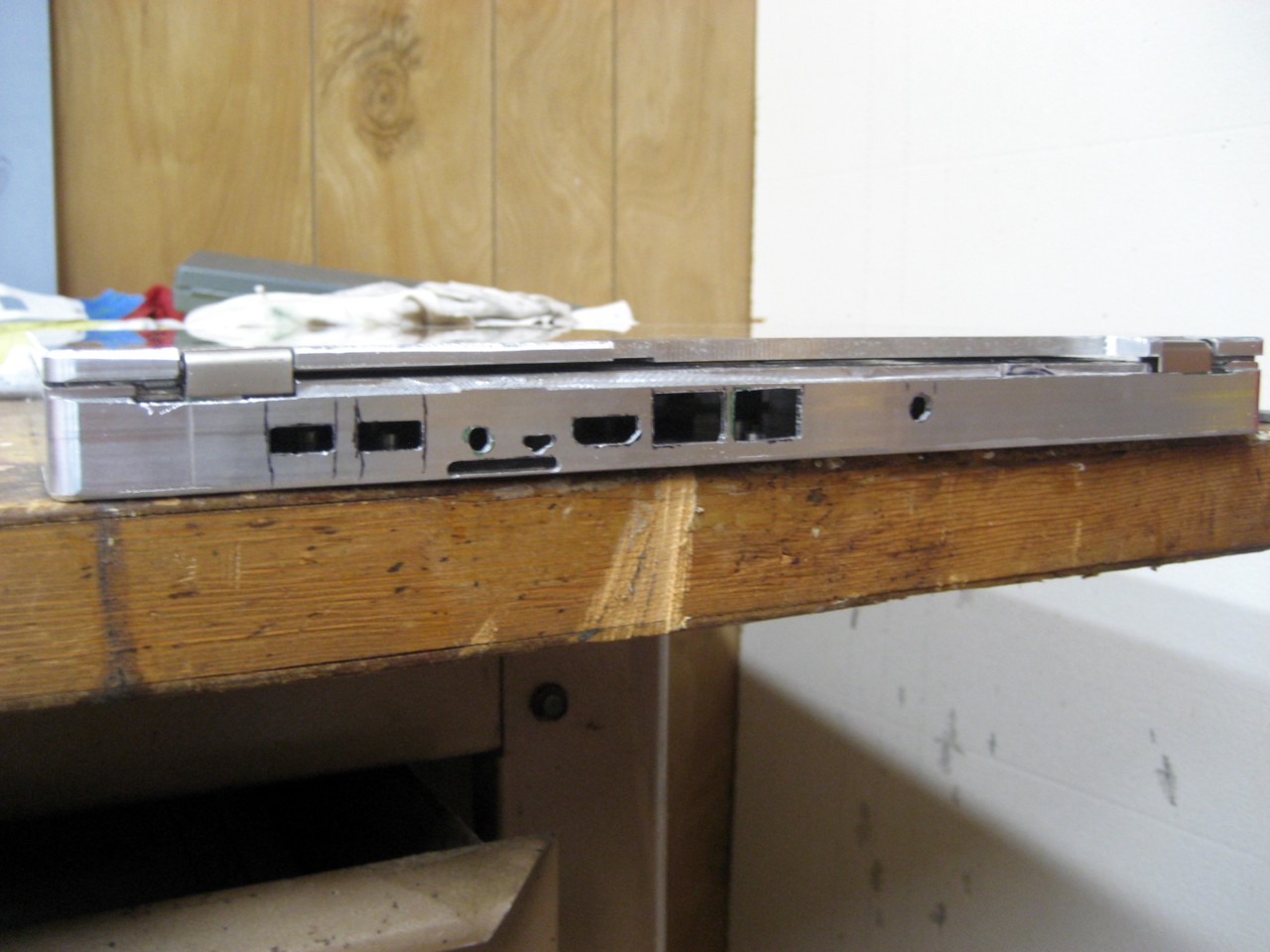
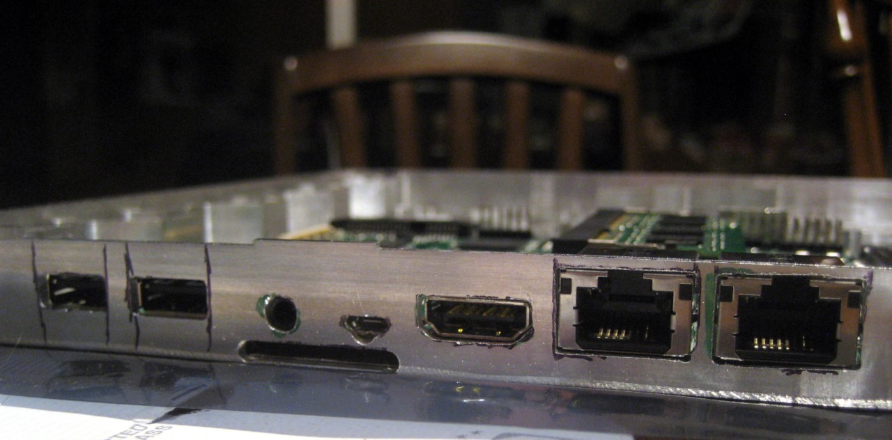
Close enough
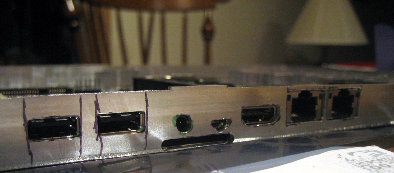
05/12/2017 at 02:45 • 0 commentsThe ports aren't perfect, but close enough. A couple still need minor work, but at least the boards fit in the right location!
I roughed the ports out on a manual mill, then finished them to size with a file and rotary tool. Probably could have just CNC'd them, but wasn't confident about the exact placement. I think it's turned out OK.
![]()
![]()
-
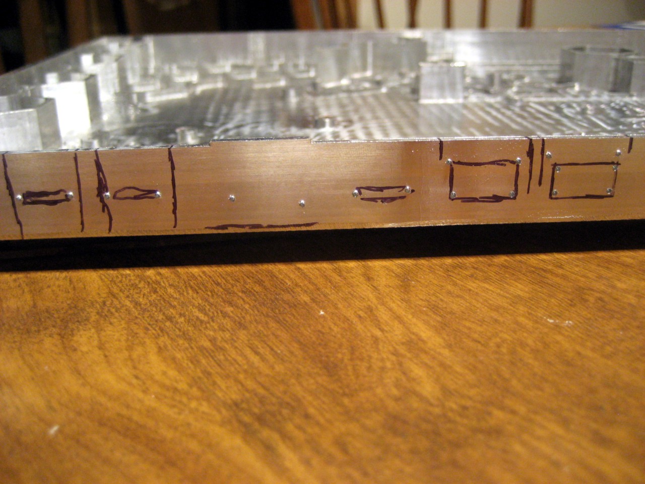
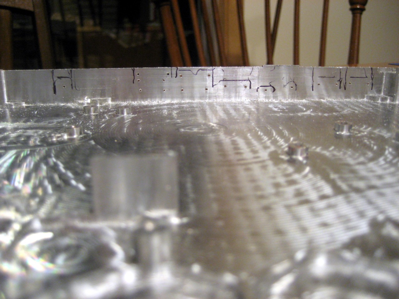
Baby steps: Countersinking holes, IO ports
05/09/2017 at 03:03 • 0 commentsCountersunk 4 holes on the keyboard retainer, and started marking/drilling the IO ports out. Very carefully this time- cutting WAY inside the outlines- which were traced on the inside directly from the ports themselves. Not sure how I'm going to cut them out yet- maybe gentle (plunge?) milling on the Bridgeport, whenever I get time to use it.
The countersinking chattered like mad- the holes are unsupported underneath- but the screws won't stick out, so I'm calling it good enough.
![]()
![]()
![]()
-
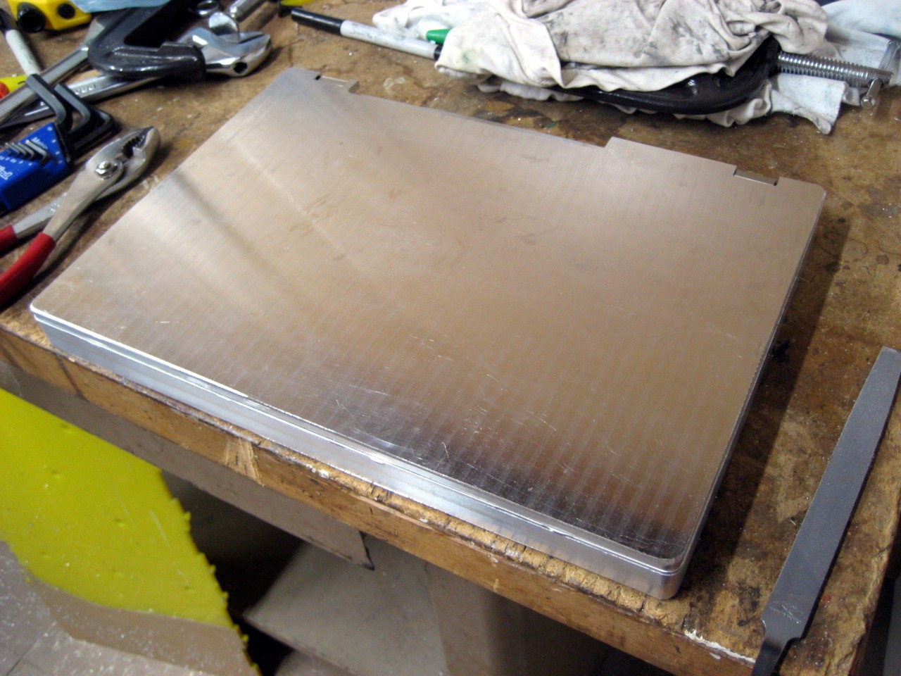
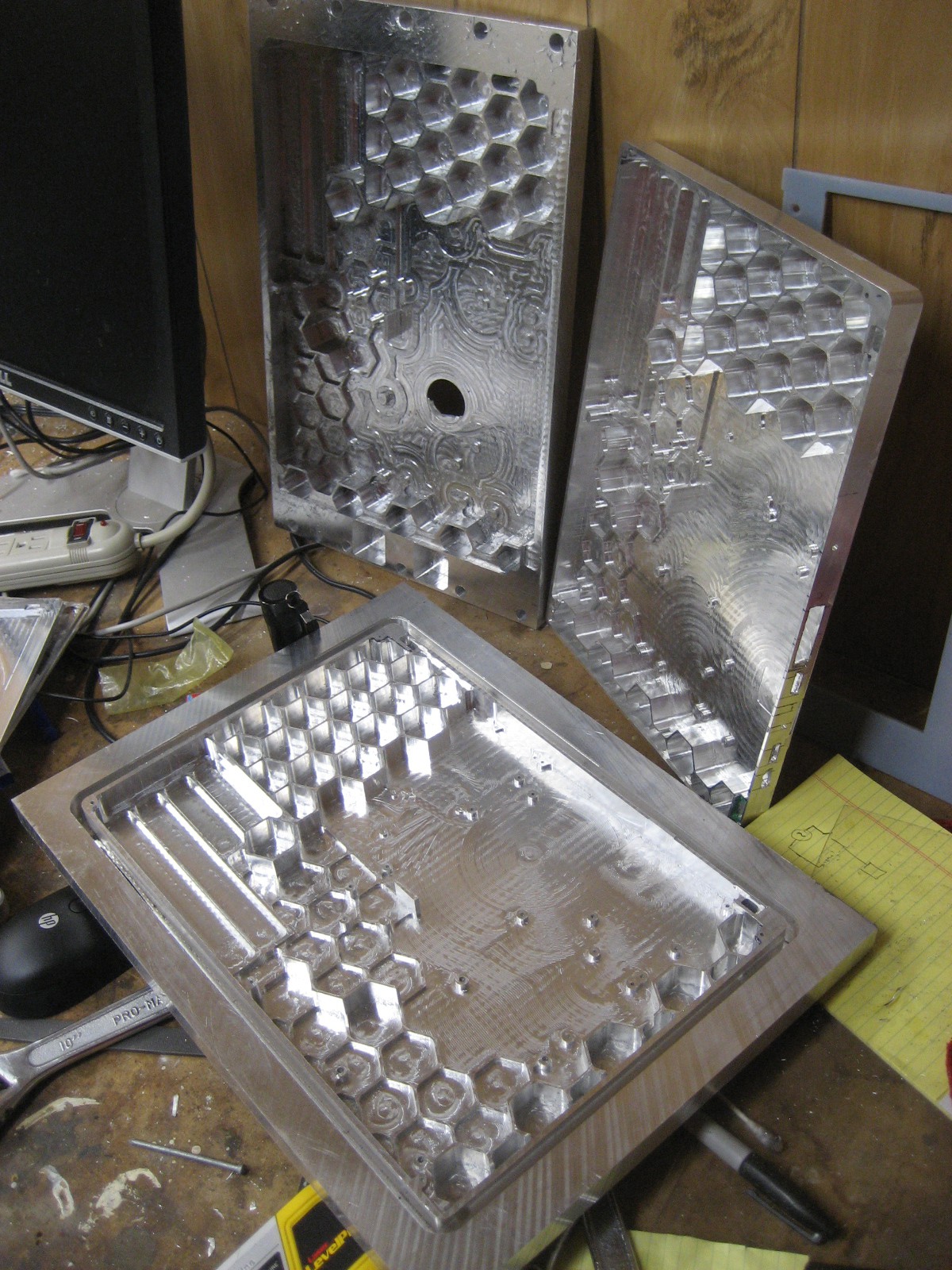
Let's do that again (base)
05/08/2017 at 04:14 • 0 commentsI'm bad with hand tools. That's why I need CNC to help me do anything. That's also why I'm sad cutting the holes for the ports on my laptop is the last step- it's easy for me to screw it up. Which I did. So... time to build a new base. Here it is all cut, and next to the previous two screw-ups:
![]()
![]()
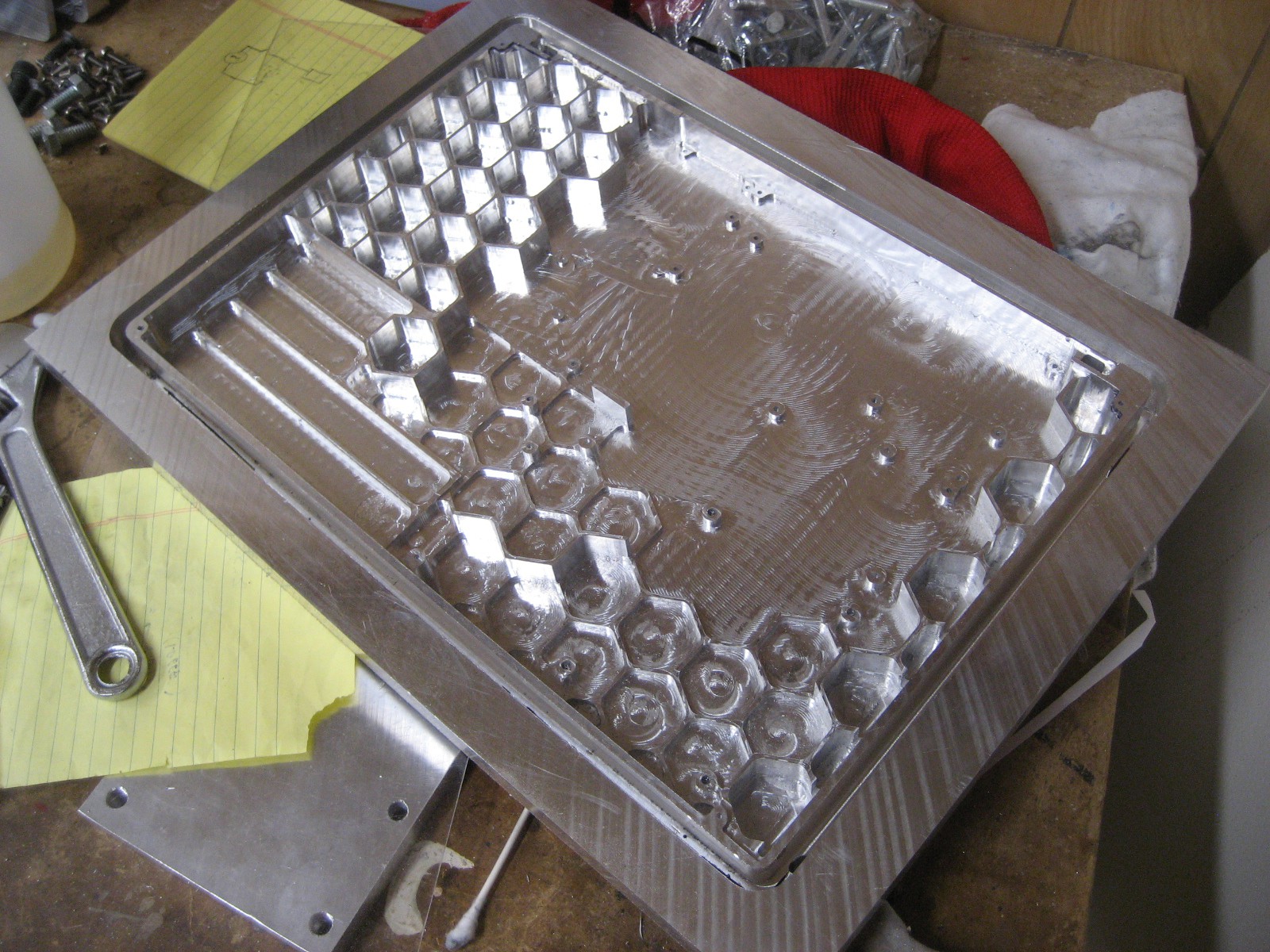
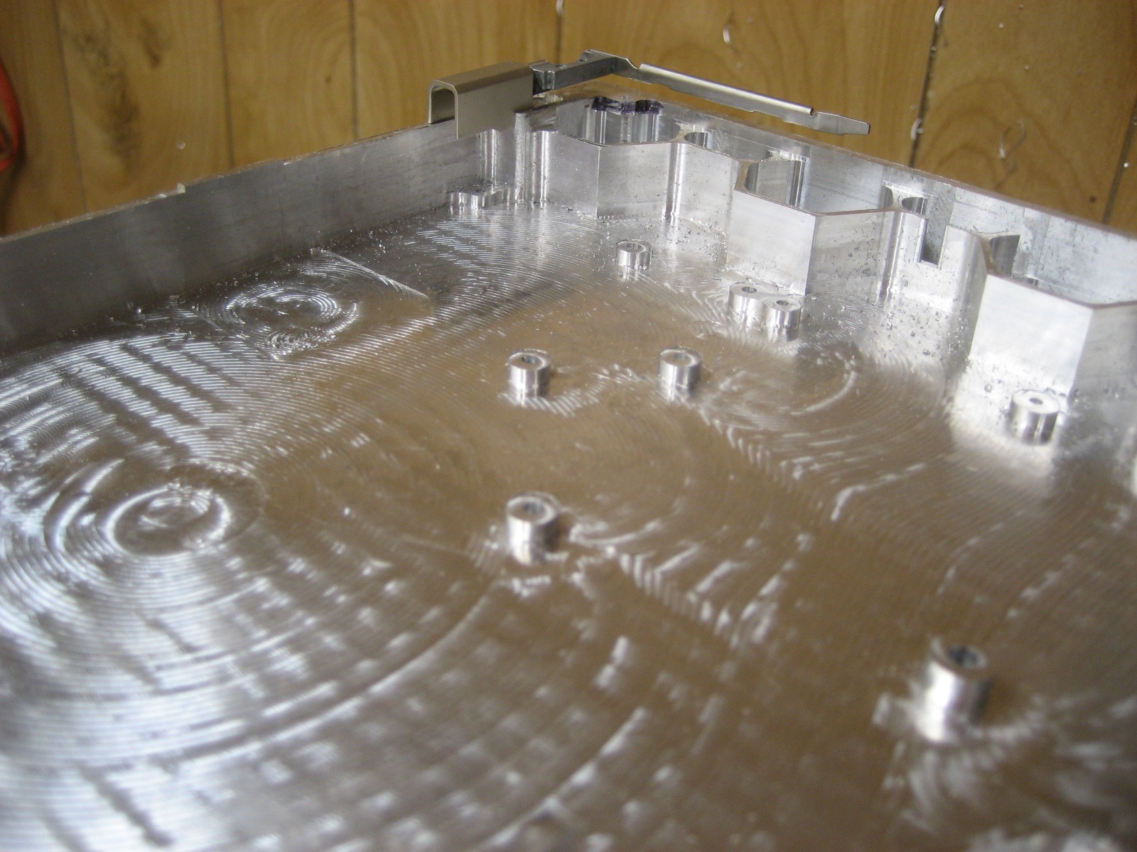
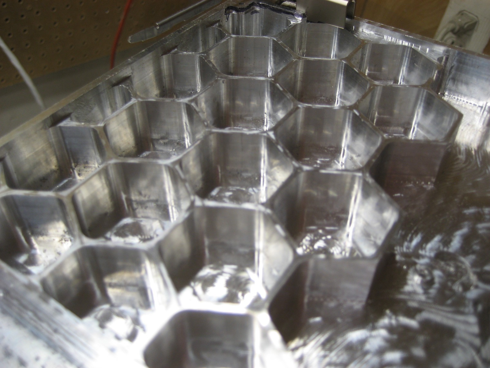
And here it is all hacked out of the stock. Well, close-ups thereof:
![]()
![]()
I'm not sure these really comes through in the images, but it looks a LOT nicer (one glaring screwup notwithstanding- that blurry indistinct blob at lower-right of the last image is a gouge going almost through the bottom). Turns out you can improve your CAM process, given the chance. I basically did a finishing pass on all of the surfaces to get rid of the high-speed machining tooling marks.
Of course, that didn't stop me from breaking two end mills down a couple holes. Don't try to machine holes deeper than your end mills are long... Anyway, I'm hoping to get those out. They're 1mm end mills in 2mm holes, so it should be doable. Otherwise I can maybe just cut the threads really short in those holes and call it good. I'd really rather not go for round 4 of building this piece.
I think rebuilding the lid is on the agenda, however. With all the metal and the screen, it's pretty heavy- I'm not sure the hinges will be happy about that. So I've skeletonized it and will re-cut it sometime soonish. Then I can also hopefully not screw it up, unlike last time (when the bottom got cut off too far). -
How fabrication is done
04/30/2017 at 16:09 • 0 commentsIn case anybody is wondering how I'm making these parts, see here:
https://hackaday.io/project/21608-serious-desktop-cnc-mill
You build a mill to build PCBs, feature creep sets in, and pretty soon you're machining giant bricks of aluminum into laptops. Who knew?
-
All previous logs
04/29/2017 at 20:20 • 0 commentsCopying this over to HaD to enter the 2017 contest. The main build log has thus far been over here:
https://sites.google.com/site/dbtayl/blog
Regarding how I've thought through the design ("Design Your Concept"), a lot of work has already gone into this. I've got 3D CAD files for the PCBs, so those should all fit in the case. I've verified this via 3D printing a test. The rest is also designed in 3D CAD, so it should fit. Most pieces have already been machined and fitted at least once.
There are two real challenges are making the darn thing, and getting the hinges right.
The former is mostly done, actually, thanks to the CNC mill I built. It's taken FOREVER, but the pieces seem to mostly fit together.
The hinges are the real challenge- I didn't have a 3D CAD model to start with, so they're drawn in as best I can measure. Right now it looks like I was slightly off in those measurements, so there's a small gap in between the lid and the keyboard when closed. I intend to see if I can hand-fit it to make it work and, barring that, re-machine the lid to fix the issues.
I guess one other point of consideration is cooling. Fortunately the CPU draws something like 3.5W fully loaded (4 cores + GPU), so passive cooling will suffice. I've already done stress-testing using just a heatpipe (no heat sink), and it stayed plenty cool. That should improve further when the heatpipe is connected to the case- the entire chassis will act as a heatsink for the machine.