Chris
Chris-
Prototype
02/07/2015 at 19:17 • 0 commentsThis was originally published on my blog: chris-labs.de
![]()
This is the second part of my RGB-Cube series (here's the first) which describes my process of forming an idea to a working prototype. After spending hours of reading and ordering the first parts the project started to take shape and it was time for some serious prototyping. In the last part I described the different ways of controlling 192 LEDs and I decided to go with shift registers (SR). They are easy to control, have a low latency and there are no glitches like when you use Charlieplexing.
After checking out some datasheets I decided to use the 74HC595 which has some nice convenience features:
- Output-Enable: Turn all outputs off at once
- Cascading: Serial output to chain multiple SRs together
- Dedicated Storage Register: Fill the storage with data without impacting the output. Then use the latch to update the output.
Problem: The 74HC959 however has a max. continuous current of only 35mA. One SR should control 8 LEDs which have a total current of 160mA (if they are all on at once). If we don't want to blow the SR we need something that can handle a little bit more current: Darlington Transistor Arrays (DTA). They are available as ICs and allow you to switch a higher current with a lower current. That means we put the DTA with 8 channels after the SR to avoid blowing our SR. The DTA model I chose was ULN2803A.
Problem: Our circuit will be powered with 5V but LEDs don't like that. That's why we need resistors after the DTA. Since I'm a lazy person and I did not want to solder 192 resistors I searched online and found Bourns Resistor Networks. Essentially it's an IC with 8 pins on each side and a resistor in between. If you use IC sockets in your final PCB you get the added advantage of quickly changing resistors to adapt the brightness of your LEDs.
Everything seems settled so now is a good time to print pin-outs of the ICs and grab a breadboard. Once that worked I wanted to create a PCB with one SR, one DTA and 8 LEDs just to make sure and to get some experience in the toner transfer method. After I figured out how to arange the ICs (SR on top, DTA on bottom) I used Eeagle to design the PCB. Use pull up / down resistors where necessary or your results might get very unpredictable. In my case I used a 10k resistor to pull OutputEnable high (disable output) and then set it low with the Arduino once I started to push some values into the SR.
![]()
![]()
![]()
Using some SPI-Code on the Arduino I got the prototype working. Nice! I could have started now and use 24 SRs to control the LEDs but then every LED would have needed three dedicated wires (red-, green-, blue-kathode) and one shared anode. That would be one ugly Cube with a lot of wires. The solution for this problem will be discussed in my next blog post. But before I end this post one more step was needed to get a smooth LED-Cube: Determining the correct resistor for each color in the RGB-LED so that when all light up at once it gives a clean white. Use a breadboard for this and after that do yourself a favor and **test every singe RGB-LED you want to use**. They vary in brightness sometimes, so take a reference LED and test them all. I built a testing rig with three reference LEDs (one for each color) and a button for each of them. Then I attached the LED to test and pressed each button to compare the colors. To better judge the brightness you can put small paper hats ontop of the LEDs, also you won't get blind this way ;)
![]()
Take aways of this post:
- Use a darlington transitor array to protect your shift register
- Use bourne resistor networks and IC-sockets to save soldering work and make your resistors exchangable
- Use pull up / down resistors where necessary to avoid erratic behaviour
- Test your LEDs for brightness
- Find the correct resistor for each color so your RGB-LED is truly white
-
Planning
07/27/2014 at 21:11 • 0 commentsThere are lots of ways to build an LED Cube. Before you start, assess how many LEDs you want to control and how fast you need to refresh the state of your LEDs for dimming and animations. In my case I had a cube of 4x4x4 RGB LEDs which are in total 192 LEDs (64 for every color). I wanted to controle them with an Arduino Nano v3.0 which I had lying around. It turned out that there are not 192 pins on this Arduino, so we need a way to control all 192 LEDs with less pins.
This is when you make your first design decision: Charlieplexing, Shiftregisters or LED-Driver-ICs ?
Charliplexing: This allows you to control a lot of LEDs with a few IOs and some resistor. No other ICs needed. It's an intresting topic and you can read more here (http://en.wikipedia.org/wiki/Charlieplexing). But there are some drawbacks:- The refresh rate is low and charliplexed RGB Cubes tend to flicker
- High peak current on single LEDs
- Some LEDs can light dimmly when not desired
- Complexity the bigger the matrix the more complex gets the circuit
I wanted a nice and smooth RGB Cube and a low refresh rate and undesired light LEDs were not an option, so I discarded this method. If you got intrested check out this Instructable on how to build an 4x4x4 LED Cube.
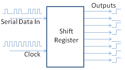
Shiftregisters: Shift registers allow you enter data in serial and output data in parallel. The most basic shift register has two inputs and several outputs. One input for data and another one for the clock. If you have a shift register with 8 outputs and want to set the first 4 outputs low and the last 4 outputs high you would do the following:
- Put clock low and data high
- Put clock high for a short amount of time
- Now the first output is set high
- Put the clock high and low three more times
Now the first 4 Outputs are high, we are not done yet. Everytime you put the clock high for a short amount of time the shift register reads the data line. Then it shifts all outputs one up and sets the first output high or low depending on the data line. To get the desired state of our shift register( first 4 low, last 4 high) we need to set the data line low and clock the shift register 4 more times. This will shift the 4 high outputs to the end and enter 4 low outputs at the beginning. There is another example in the pictuer below, it sets the output to 10110111.
![]()
Shift registers usually have some more features:
A serial output line. After you put data in 8 times every new clock cycle will push one output state at the end of the shift register out to the serial output line. This allows you to chain multiple shift registers.
Another feature is the output enable line. If you have 8 leds connected to a shift register and you want to put the first 4 low and the last 4 high. Then you need to shift 1111000 to the register. In the process you can observer that the first 4 leds start to light up and then move to the end of the line with every clock cycle. If you don't want to have the shift process you use the output enable line. You pull the output enable line low, and shift your 1111000 to the register. The output will not change until you put the output enable line high again. This way the shift process is not visible.
If you use shift registers for your project you need some transistors after them because they cannot handle the current of several LEDs lit at once. This is why I used Darlington Transistor Arrays. They come as an IC and you don't have to solder a lot of single transistors and pull-up/down resistors to your board. After the transistor array you also need some pre-resistors depending on your LED (because they cannot handle 5V). If you are lazy like me, you buy Resistor Array ICs and put them in sockets. This way you can easyly solder the socket and exchange the resistor array later to adjust the brightness of your LEDs.
LED-Driver-ICs: If you don't want to use Charlieplexing or shift registers then you could also use LED-Driver-ICs. They can be controlled like shift registers and have the darlington transistor array and pre-resistors for the LED already inside. But where is the fun in that? ^^ If however you want to use something like this, have a look at the MY9221. They allow you to control 4 RGB LEDs per IC ( in total 16 LEDs) with up to 60mA per LED.
Conclusion: I went for the shift registers because charlieplexing was not an option and LED-Driver-ICs just seemed to simple ;)
IoT RGB Led Cube 4x4x4 with Bluetooth
To dive a little deeper into eletronics and arduino programming, I created an 4x4x4 RGB Led Cube. Bluetooth is still to be done.