James Ots
-
Oscillator
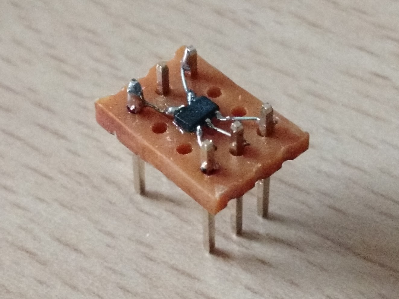
06/20/2017 at 20:04 • 0 commentsInstead of using a 16MHz crystal, two resistors, a capacitor and a 74LS04 to create my computer's clock, I'm now using an LTC6900 oscillator, which can produce any frequency between 1 kHz and 20 MHz, depending on the value of a resistor. I didn't have any TSOT-23 adaptors, so I made my own using a piece of upside-down stripboard, some super-glue (to hold it in place before it was soldered) and some tiny wires. It works. (As you can probably tell from the neatness (or not) of the soldering, I started on the far side, and finished with the pin in the middle on this side.)
I still have to feed this clock into the CPLD and then take it out to the Z80 (mainly because I like having the option to slow down the clock if I want in the CPLD), but I'm using a 74HCT04 this time, which should be producing the correct voltage for the Z80. Even though it seemed quite happy with the LS version, I thought I'd at least try to be correct.
Oh, and as expected, I had to add a wait state into the ROM access, as going from 8 MHz to 10 MHz has taken it just past the ROM's timing limits.
![]()
-
Proof
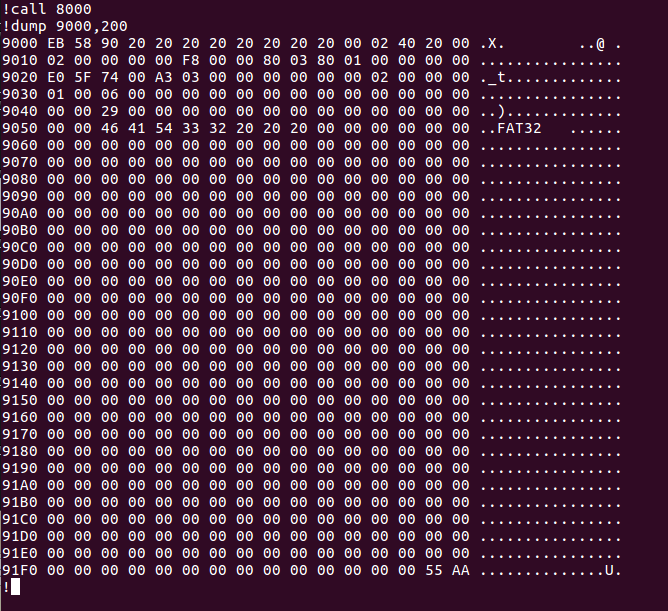
06/17/2017 at 22:19 • 0 commentsI'm kind of excited about managing to get my Z80 computer to talk to an SD card. Here's proof that it works - the BPB of my SD card.
![]()
-
SD Card SPI
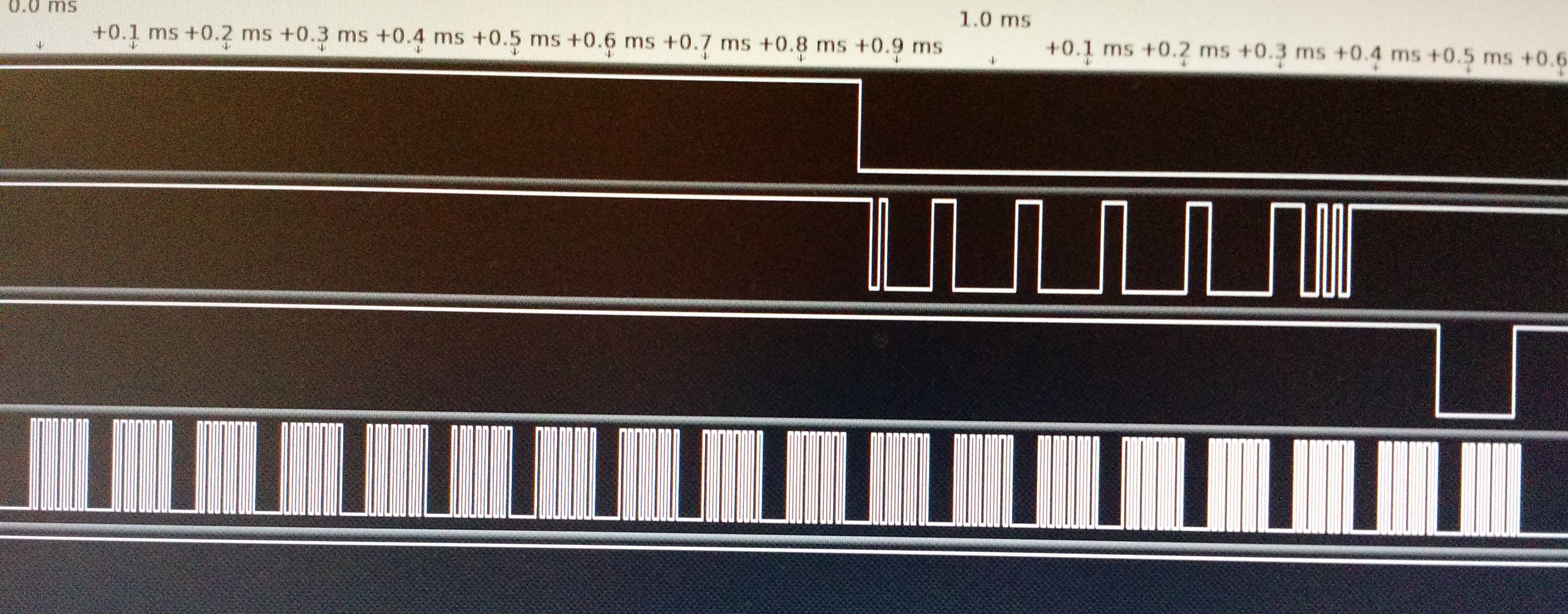
06/17/2017 at 19:46 • 0 commentsFinally, something slightly more exciting. To me, anyway. I've just got my SD card to respond to a CMD0! I'm not at all pleased with how the CPLD code looks, but it works and I can't work out how to do it better at the moment.
If you send a byte to port 10, the CPLD will transfer it to the SD card, while reading a byte back, which you can then see by reading port 10. You can write to port 11 to change the SD card's CS line, and you can read from it to get the current value of CD and DO, and to see if the CPLD is still busy writing to the SD card.
...and now later in the day...
I've written some Z80 routines which properly initialise the SD card and read some data from it. I don't know if the data is right as I haven't done anything to write to the card yet! Also, it doesn't negotiate anything - I've assumed that everyone that uses this code uses the SD card I have right now!
![]()
-
Really Booting from the ROM
06/15/2017 at 18:03 • 1 commentPreviously, although I could boot from the ROM, I found that after a while it stopped working. I eventually worked out that it was down to two things: 1. I hadn't write protected the ROM and 2. there was a bug in the monitor code which was accidentally overwriting itself. Now that I've written a PROTECT (and UNPROTECT) routine, and fixed the bug, booting from the ROM works nicely.
One interesting thing which I hadn't initially thought of was that when the system is running from the ROM instead of from RAM it isn't possible to write to the ROM. This is because once you've written to the ROM it goes into a mode where each byte you read is different from the previous one until the write has completed. So as soon as you write to the ROM then the next instruction it reads from the ROM is incorrect and it crashses. So I should probably load the ROM programme into RAM as soon as it has booted.
And after that I can start work on the SD card.
-
Booting From ROM
06/13/2017 at 21:19 • 0 commentsWoohoo! My rom writing code works, I've modified the Z80 Monitor programme to work from ROM, and now I can switch my computer on and it comes straight up with the monitor programme without me having to bootstrap anything. Hooray!
I guess now I have to implement the LOAD command, and then get the SD card working.
-
Annotated Photo
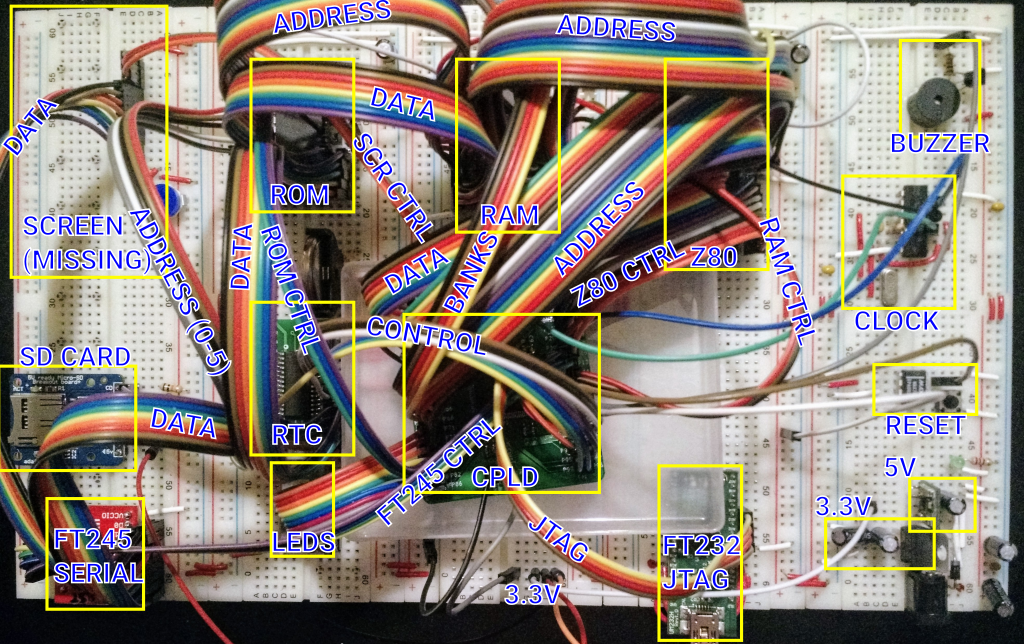
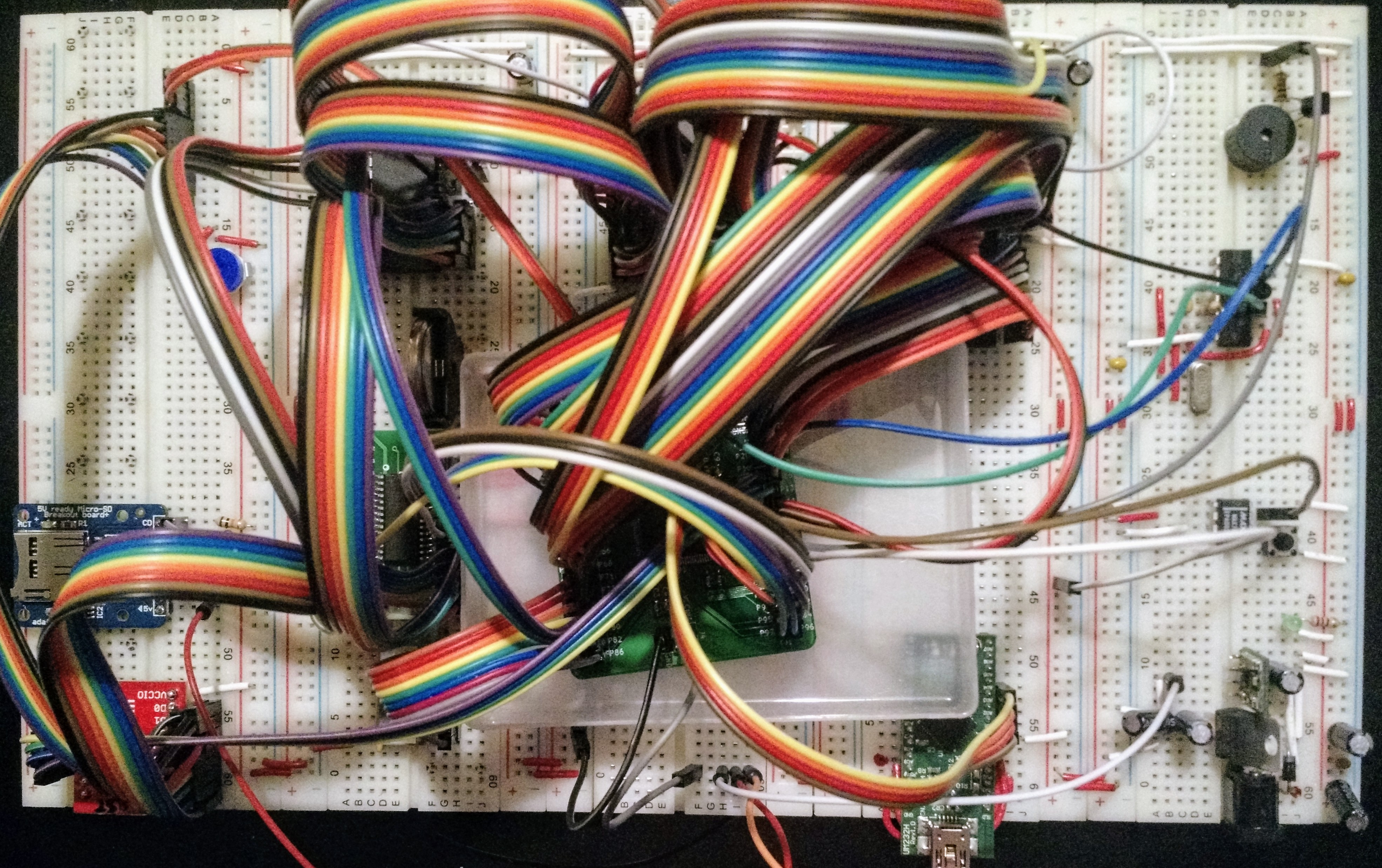
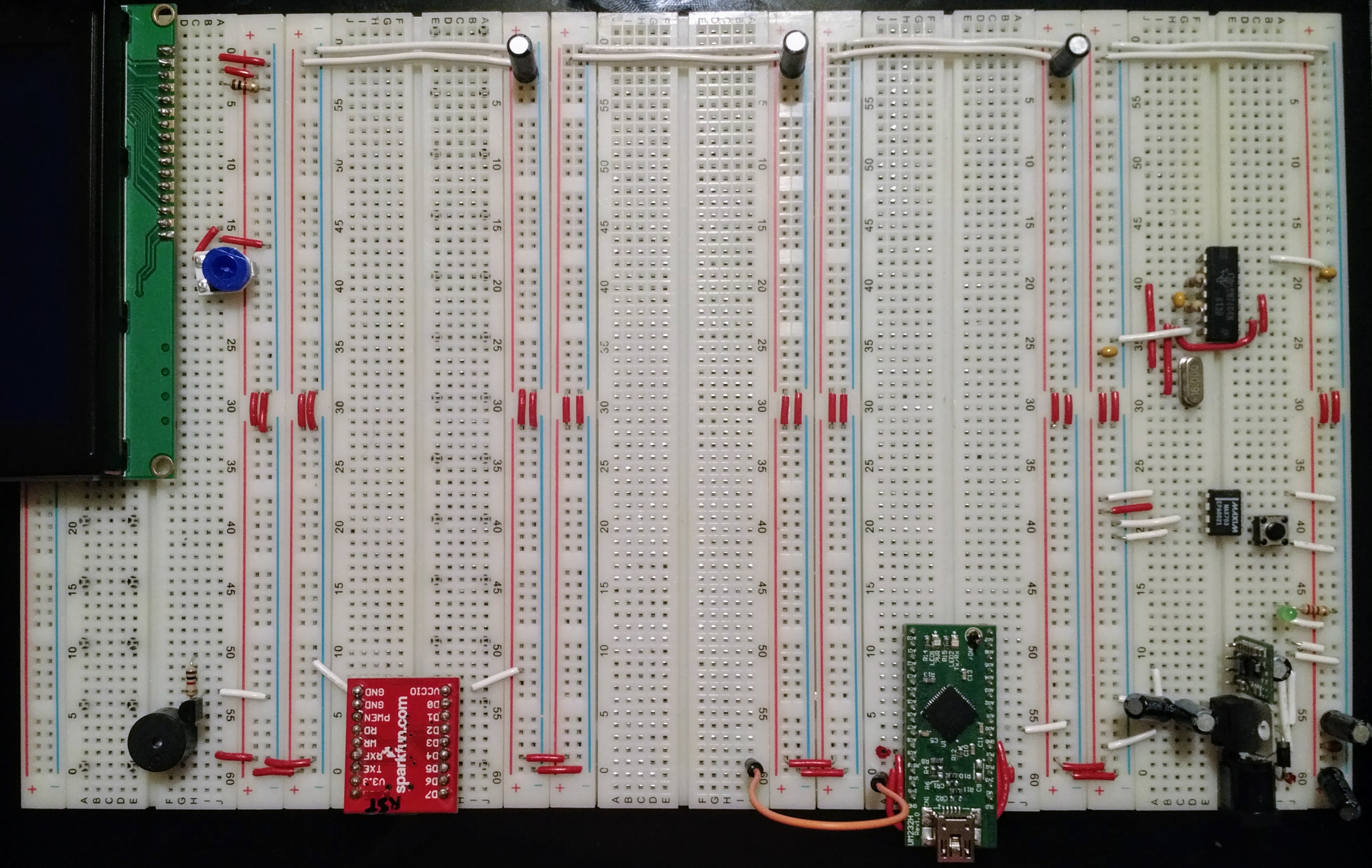
06/13/2017 at 11:51 • 0 commentsHere's the breadboard with labels:
![]()
-
Good News
06/12/2017 at 19:53 • 1 commentI have my computer working again. The main problem was the ROM_BOOT_N signal, which I had coming into the CPLD on GTS1, which is pin 3. The CPLD didn't seem to be reading this signal (I don't know if it's badly soldered, if the input is blown, or if I'm not supposed to use GTS1 for some inexplicable Xilinx reason), and so the computer was always trying to boot from the ROM. I've now moved it onto GTS3 (pin 1), and it seems to be working. And I'm able to write to the ROM if I do it with a PEEK command in my monitor, but not with a COPY. So I need to debug that.
-
Power Struggle
06/12/2017 at 08:27 • 0 commentsI've got everything wired up on the new board. I reorganised it a little so that both the USB ports and the power are all on the same side. The buzzer has been moved over to the right will all the other small components. The RTC has been moved over to the left so that the address and data busses have a more sane route around the board.
And it didn't work. After a long time checking things I discovered two problems. The RD and WR lines on the FTDI were swapped, and one of the wires on the clock was bent up underneath itself and then into the wrong hole so that it was almost impossible to see that it was miswired.
After I fixed these problems and slowed the clock down in the CPLD I was able to make it flash an LED on and off, so I knew that I'd at least got the clock working. But it was still failing to read from the FTDI.
And then everything stopped working, and all the LEDs went dim. I measured the voltages, and the 5V and 3.3V lines were reading about 3V and 2V respectively, and the 3V regulator was really hot. I switched off the power, and reaslised that the CPLD board's pins were touching the power links which this board has halfway down each side, which the previous board didn't need. I think I may have blown up the CPLD board, so I switched it out for my spare one and put it in a plastic tray this time. I also switched out most of the other chips I have, just in case.
I then wrote a CPLD configuration which is effectively Thomas Sherrer's minimal Z80 tester and switched the power on. The address lines are succesfully counting, so I now know I have a working Z80. Then I plugged in a USB cable and the lights all went dim again. But this time, after switching the power off and on again then everything was working fine. So I'm wondering if I've managed to partially destroy a power regulator. The shutdown line of the 5V regulator was unconnected, which is apparently okay, but I've now tied it to Vin just to be sure. And I've disconnected the screen as I wasn't sure if it was causing problems. I think I'll have to get a replacement 5V regulator as well — I've already changed the 3.3V one as I had a bunch of spares.
I also measured the current from each regulator — 300mA are being drawn from the 3.3V one, and 400mA from the 5V one (which includes the 300mA from the 3.3V regulator). Which would suggest there's probably no wiring problem at the moment. The 3.3V regulator does seem to be getting hotter than it did on the old board, although I might be misremembering that.
![]()
-
New Board
06/07/2017 at 22:08 • 0 commentsThe change I made to the code last night worked. However, there were still some problems, and I discovered that there were definitely some loose connections on the board. Lots of very loose connections actually. So I cleared off my old breadboard (which has much better connectors) and I've started to rebuild my computer on it. Which is surprisingly difficult to do without forgetting where all the wires were previously, so I'm taking a lot of photos as I go.
![]()
-
The Drugs Don't Work
06/07/2017 at 07:22 • 0 comments"When high, do not read data from the FIFO." — FT245R Datasheet
Well, I think I've found out why the FT245R was behaving erratically. To read from it I was setting RD low, and then waiting until RXF went low. But the datasheet says that you shouldn't read data when RXF is high, so I'm guessing that's why it only worked sometimes.
Yesterday I tried slowing the clock down in order to debug something else, an no matter what I did, I couldn't read any data from the FT245R. I hooked up some LEDs to different signals and found it wasn't behaving as expected, and then I re-read the data sheet. After fixing the CPLD code to only set the FTDI's RD line low once data is actually available, I can now drop the clock speed right down and it still works.
This is hopefully the correct solution, and not just another random red herring.