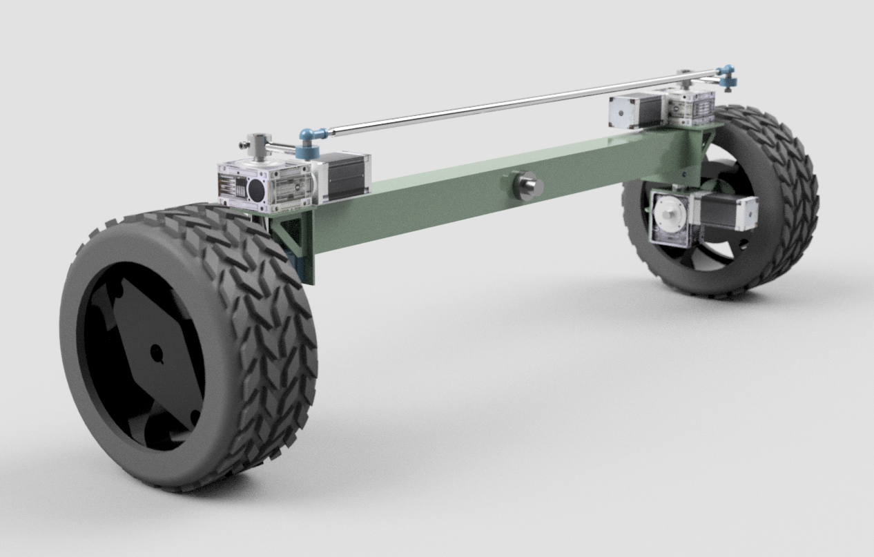
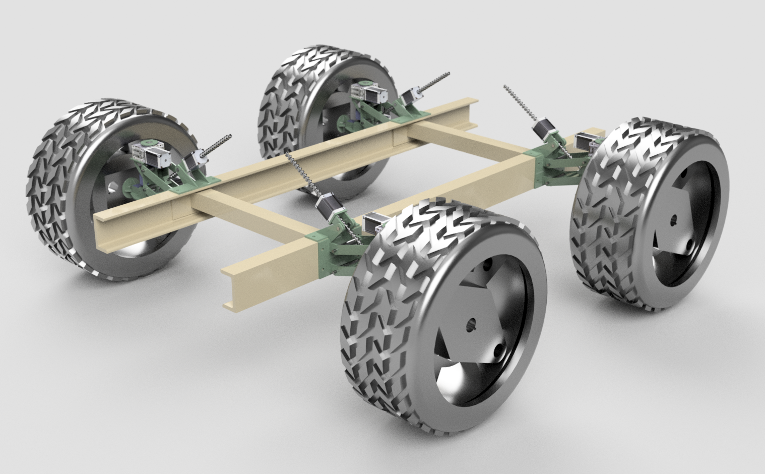
This design is based on an International 454 tractor and the fixed axle swivels about the XY plane, whilst the rear axle remains static, as shown in the video below:
The steering is linked together to eliminate backlash in the steering gearboxes.
Whilst waiting to start build a second wheel drive mechanism, I thought I'd have a tinker on Fusion 360 and look at the actual weeding / cultivation mechanism. This is necessary in terms of the chassis build as it would be nice to get the CNC machine embedded into the chassis rather than sitting on top of it, which should (hopefully) save a lot of weight.
The initial testing went well. The steering lock was much better than anticipated and the motors seemed to have adequate torque with the electronic driver unit used. An ammeter revealed that the electronic driver should be upgraded to get the full complement of electrons flowing through the coils.
Finally, after many weeks of constant toil, the drive mechanism is assembled and ready for testing. So far, so good - no obvious faults and everything moves without bumping into over parts.
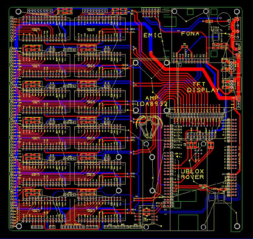
The driver requires 5V signals to run it and I've set out the PCB above with a whole load of 5V Arduino Nanos networked with a master Arduino Due (or MEGA) with data transmitted via I2C. I'm guessing that each Nano can control 2 motors with accelerations as, from memory, there are 4 timers available on each board. Could be wrong on several accounts, but I've incorporated enough redundancy and extra features such as logic level shifting to cobble together something from my PCB that will almost certainly work. I'm giving it odds of 99%.
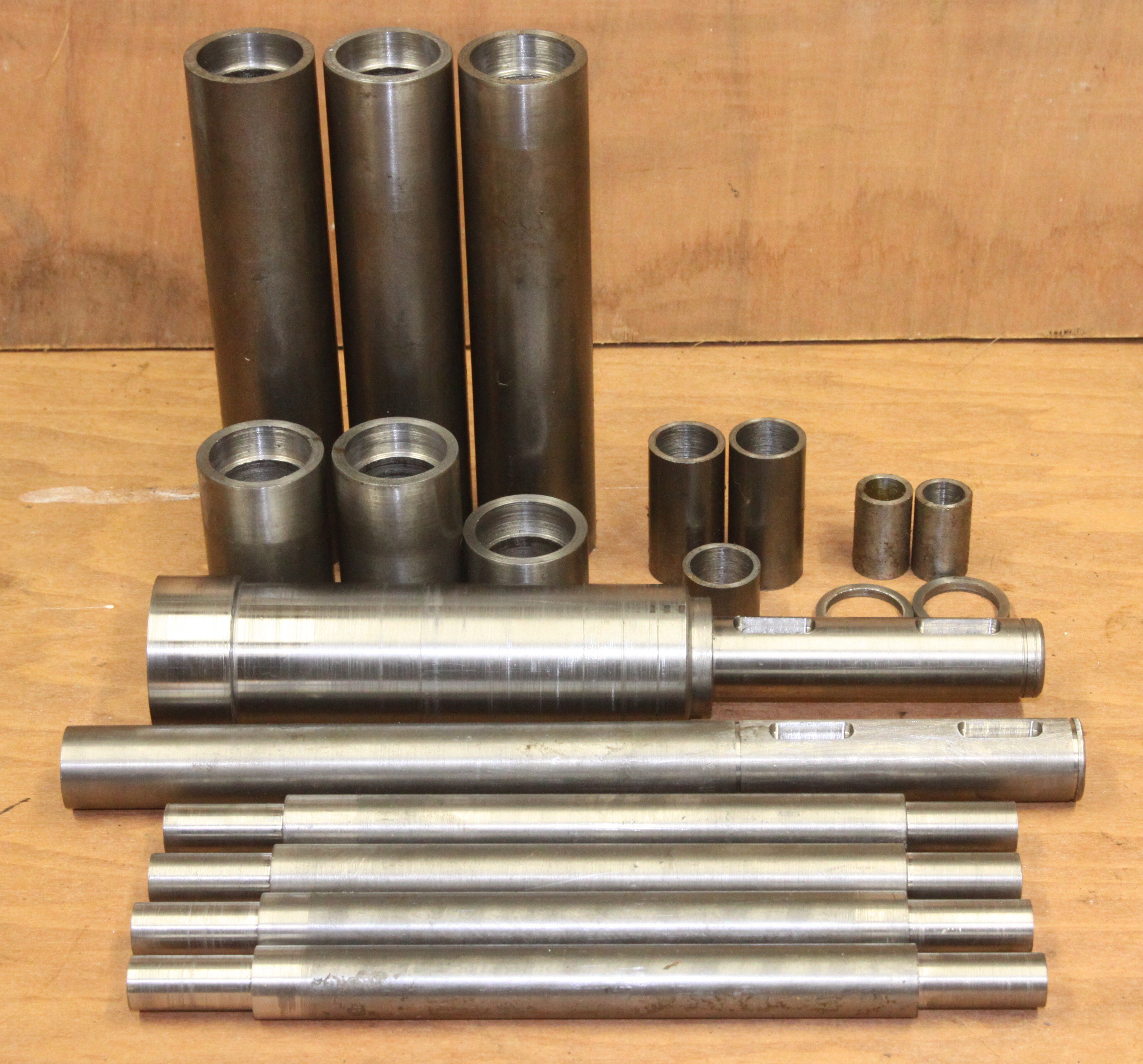
I've now got a load of cylinders of various sizes to fit together with the laser cut parts. The big fat one in the middle of the photo is the steering, which needs to be fairly beefy due to the leverage forces due to the offset wheel position.
Eventually, with some help from some friends, I tracked down an industrial sized lathe that I could work on. A local engineering company, namely DMM came up trumps, for which I am forever grateful!
For now I am just working on one single wheel mechanism so that it can be tested. Simultaneously, I am still trying to get a high power stepper motor control board working. New PCBs arrived yesterday - there was an unfixable fatal error with the last version so daytime is to be spent populating the PCB and night time working on the lathe. Who needs sleep?
In between everything else, I'm still working on the CAD design and have managed to get all four wheel assemblies onto a chassis, which is quite satisfying.
The laser cut parts have arrived and I've finally worked out how to build the steering mechanism properly - seems like the steering shaft itself needs to be beefed up on the lower side to sustain the leverage forces created by the offset centre of the wheel. The shaft starts of as being 25mm and then eventually steps up to 50mm at the point where it is welded to the plate on top of the transmission gearbox, at it's point of maximum weakness.
The downward forces on the bearings are not great so everyday ball roller type should be fine as they will sustain an axial force of about 20% of the radial forces. I'm not quite sure what will happen when they start to where down as currently there's no provision for adjustment.
The transmission shaft looks similar to the above but is a straight 25mm OD as it has support bearings right up close to the actual wheel and consequentially much less leverage force compared to the steering.
 Capt. Flatus O'Flaherty ☠
 This design is based on an International 454 tractor and the fixed axle swivels about the XY plane, whilst the rear axle remains static, as shown in the video below:
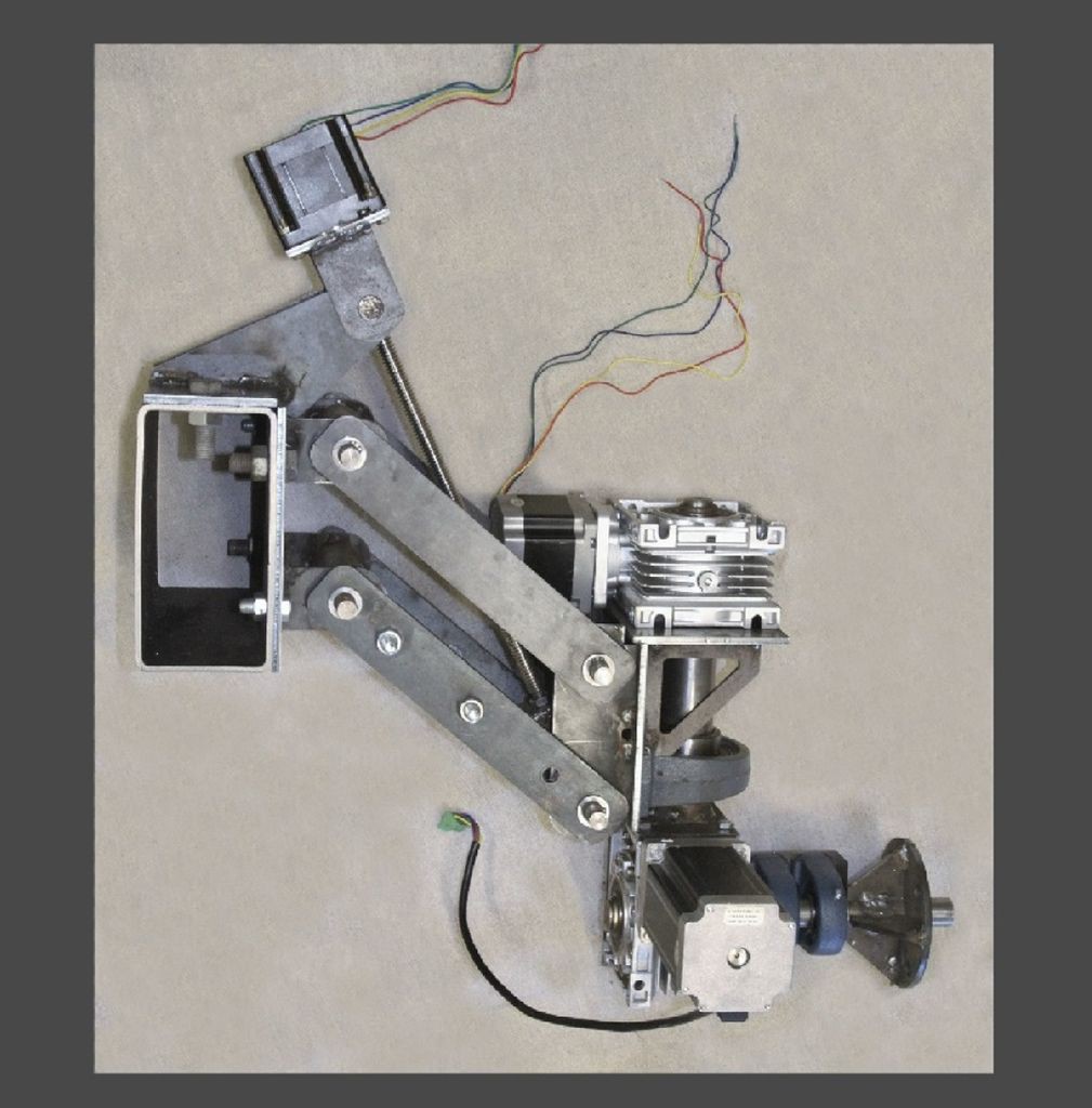
 I've now abandoned the idea of making my own stepper motor drivers and gone for the ready mage Chinese driver instead:
 I've now got a load of cylinders of various sizes to fit together with the laser cut parts. The big fat one in the middle of the photo is the steering, which needs to be fairly beefy due to the leverage forces due to the offset wheel position.
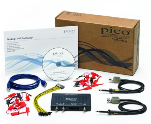
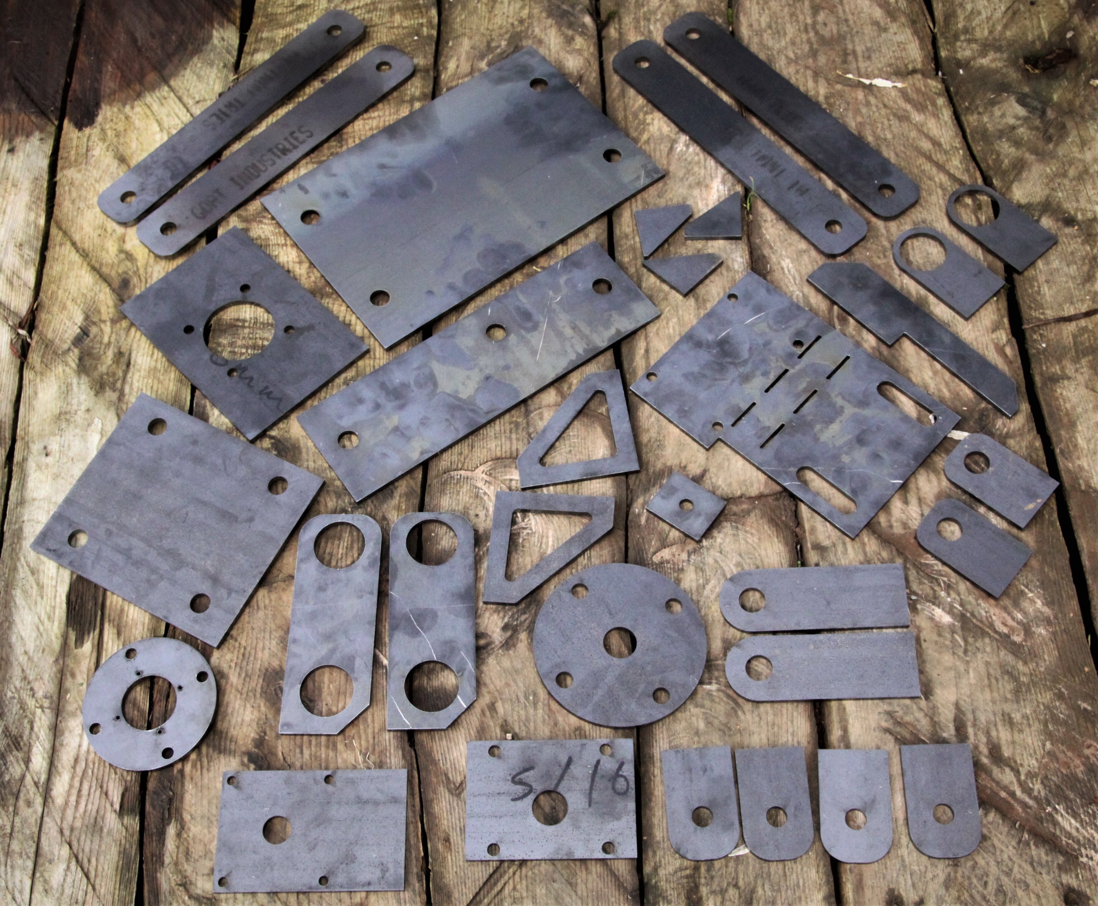 The laser cut parts have arrived and I've finally worked out how to build the steering mechanism properly - seems like the steering shaft itself needs to be beefed up on the lower side to sustain the leverage forces created by the offset centre of the wheel. The shaft starts of as being 25mm and then eventually steps up to 50mm at the point where it is welded to the plate on top of the transmission gearbox, at it's point of maximum weakness.