GOAT INDUSTRIES
-
WEEDINATOR Does Doughnuts
01/28/2018 at 15:34 • 0 commentsThe control system has been switched to a 3 core MCU running at 200 MHz, the 'ShieldBuddy'. This enabled the whole steering and drive system to be hosted on one device. The first core runs 330 lines of code to control the stepper motors with full differential on both the steering and drive, using the 'micros' function. The next core has serial debugging and a 4 second delay so that it can be read easily. The third core oversamples some potentiometers to control the machine on a 5 core cable.
/*** Don't worry, the normal Arduino setup() and loop() are below this block! ***/ /* LMU uninitialised data */ StartOfUninitialised_LMURam_Variables /* Put your LMU RAM fast access variables that have no initial values here e.g. uint32 LMU_var; */ EndOfUninitialised_LMURam_Variables /* LMU uninitialised data */ StartOfInitialised_LMURam_Variables /* Put your LMU RAM fast access variables that have an initial value here e.g. uint32 LMU_var_init = 1; */ const int ledPin = 13; int ledStateOne = LOW; int ledStateTwo = LOW; int ledStateThree = LOW; int ledStateFour = LOW; unsigned long previousMicrosOne = 0; unsigned long previousMicrosTwo = 0; unsigned long previousMicrosThree = 0; unsigned long previousMicrosFour = 0; long intervalOne = 1000; long intervalTwo = 1000; long intervalThree = 1000; long intervalFour = 1000; int difference=0; int previousFinalSteeringValue=15300; long rightWheel=0; long leftWheel=0; long wheelsPosition=0; int finalDriveValue=0; long finalSteeringValue =0; EndOfInitialised_LMURam_Variables /*** Core 0 ***/ void setup() { delay(5000); pinMode(ledPin, OUTPUT); pinMode(5,OUTPUT); //STEP pinMode(6,OUTPUT); //DIRECTION HIGH is clockwise pinMode(7,OUTPUT); //STEP pinMode(8,OUTPUT); //DIRECTION HIGH is clockwise pinMode(9,OUTPUT); //STEP pinMode(10,OUTPUT); //DIRECTION HIGH is clockwise pinMode(11,OUTPUT); //STEP pinMode(12,OUTPUT); //DIRECTION HIGH is clockwise } void loop() { unsigned long currentMicrosOne = micros(); unsigned long currentMicrosTwo = micros(); unsigned long currentMicrosThree = micros(); unsigned long currentMicrosFour = micros(); speedDifferential(); if (finalDriveValue>=600) //Forwards. { intervalThree = (600000/finalDriveValue)-300; // 250 is max speed. intervalFour = (600000/finalDriveValue)-300; // 250 is max speed. speedDifferential(); digitalWrite(10,HIGH); digitalWrite(12,HIGH); if (currentMicrosThree - previousMicrosThree >= intervalThree) { changeStateThree(); digitalWrite(9,ledStateThree); // Drive motor step } if (currentMicrosFour - previousMicrosFour >= intervalFour) { changeStateFour(); digitalWrite(11,ledStateFour); // Drive motor step } } if (finalDriveValue<400) //Backwards. { intervalThree = (finalDriveValue*2)+250; // 250 is max speed. intervalFour = (finalDriveValue*2)+250; // 250 is max speed. speedDifferential(); digitalWrite(10,LOW); digitalWrite(12,LOW); if (currentMicrosThree - previousMicrosThree >= intervalThree) { changeStateThree(); digitalWrite(9,ledStateThree); // Drive motor step } if (currentMicrosFour - previousMicrosFour >= intervalFour) { changeStateFour(); digitalWrite(11,ledStateFour); // Drive motor step } } ////////////////////////////////////////////////////////////////////////////////////////////////////// difference = finalSteeringValue - previousFinalSteeringValue; ////////////////////////////////////////////////////////////////////////////////////////////////////// if((difference>500)&&(wheelsPosition>=0)) // Clockwise from the centre { clockWise(); if (currentMicrosTwo - previousMicrosTwo >= intervalTwo) // Right wheel (SLOW) { changeStateTwo(); digitalWrite(7,ledStateTwo); //STEP } if (currentMicrosOne - previousMicrosOne >= intervalOne) // Left wheel (FAST) { changeStateOne(); digitalWrite(5,ledStateOne); //STEP wheelsPosition++; previousFinalSteeringValue++; // This must be within backets containing 'changeStateOne'. } } ////////////////////////////////////////////////////////////////////////////////////////////////////// if((difference>500)&&(wheelsPosition<0)) // Clockwise from the full lock position { clockWise(); if (currentMicrosOne - previousMicrosOne >= intervalOne) // Right wheel (FAST) { changeStateOne(); digitalWrite(7,ledStateOne); //STEP wheelsPosition++; previousFinalSteeringValue++; // This must be within backets containing 'changeStateOne'. } if (currentMicrosTwo - previousMicrosTwo >= intervalTwo) // Left wheel (SLOW) { changeStateTwo(); digitalWrite(5,ledStateTwo); //STEP } } ////////////////////////////////////////////////////////////////////////////////////////////////////// if((difference<-500)&&(wheelsPosition>=0)) // Anti-clockwise from the full lock position { antiClockWise(); if (currentMicrosTwo - previousMicrosTwo >= intervalTwo) // Right wheel (SLOW) { changeStateTwo(); digitalWrite(7,ledStateTwo); //STEP } if (currentMicrosOne - previousMicrosOne >= intervalOne) // Left wheel (FAST) { changeStateOne(); digitalWrite(5,ledStateOne); //STEP wheelsPosition--; previousFinalSteeringValue--; // This must be within backets containing 'changeStateOne'. } } ////////////////////////////////////////////////////////////////////////////////////////////////////// if((difference<-500)&&(wheelsPosition<0)) // Anti-clockwise from the centre { antiClockWise(); if (currentMicrosOne - previousMicrosOne >= intervalOne) // Right wheel (FAST) { changeStateOne(); digitalWrite(7,ledStateOne); //STEP wheelsPosition--; previousFinalSteeringValue--; // This must be within backets containing 'changeStateOne'. } if (currentMicrosTwo - previousMicrosTwo >= intervalTwo) // Left wheel (SLOW) { changeStateTwo(); digitalWrite(5,ledStateTwo); //STEP } } ////////////////////////////////////////////////////////////////////////////////////////////////////// difference = finalSteeringValue - previousFinalSteeringValue; } /*** Core 1 ***/ /* CPU1 Uninitialised Data */ StartOfUninitialised_CPU1_Variables /* Put your CPU1 fast access variables that have no initial values here e.g. uint32 CPU1_var; */ EndOfUninitialised_CPU1_Variables /* CPU1 Initialised Data */ StartOfInitialised_CPU1_Variables /* Put your CPU1 fast access variables that have an initial value here e.g. uint32 CPU1_var_init = 1; */ EndOfInitialised_CPU1_Variables void setup1() { SerialASC.begin(9600); } void loop1() { SerialASC.print("Steering Value= ");SerialASC.println(finalSteeringValue); SerialASC.print("Previous steering Value= ");SerialASC.println(previousFinalSteeringValue); SerialASC.print("Difference= ");SerialASC.println(difference); SerialASC.print("wheelsPosition= ");SerialASC.println(wheelsPosition); SerialASC.print("Drive= ");SerialASC.println(finalDriveValue); SerialASC.print("IntervalThree= ");SerialASC.println(intervalThree); SerialASC.print("IntervalFour= ");SerialASC.println(intervalFour); SerialASC.println(""); delay(4000); } /*** Core 2 ***/ /* CPU2 Uninitialised Data */ StartOfUninitialised_CPU2_Variables /* Put your CPU2 fast access variables that have no initial values here e.g. uint32 CPU2_var; */ EndOfUninitialised_CPU2_Variables /* CPU2 Initialised Data */ StartOfInitialised_CPU2_Variables /* Put your CPU2 fast access variables that have an initial value here e.g. uint32 CPU2_var_init = 1; */ long driveValue=0; long steeringValue =0; int i=0; EndOfInitialised_CPU2_Variables void setup2() { // put your setup code for core 2 here, to run once: } void loop2() { steeringValue=0; driveValue=0; i=0; while(i<200) { steeringValue = steeringValue + analogRead(A0); driveValue = driveValue + analogRead(A1); i++; } finalDriveValue = driveValue/i; finalSteeringValue = 30*steeringValue/i; delay(10); } void changeStateOne() { unsigned long currentMicrosOne = micros(); previousMicrosOne = currentMicrosOne; if (ledStateOne == LOW) { ledStateOne = HIGH; } else { ledStateOne = LOW; } digitalWrite(ledPin, ledStateOne); } void changeStateTwo() { unsigned long currentMicrosTwo = micros(); previousMicrosTwo = currentMicrosTwo; if (ledStateTwo == LOW) { ledStateTwo = HIGH; } else { ledStateTwo = LOW; } digitalWrite(ledPin, ledStateTwo); } void changeStateThree() { unsigned long currentMicrosThree = micros(); previousMicrosThree = currentMicrosThree; if (ledStateThree == LOW) { ledStateThree = HIGH; } else { ledStateThree = LOW; } digitalWrite(ledPin, ledStateThree); } void changeStateFour() { unsigned long currentMicrosFour = micros(); previousMicrosFour = currentMicrosFour; if (ledStateFour == LOW) { ledStateFour = HIGH; } else { ledStateFour = LOW; } digitalWrite(ledPin, ledStateFour); } void clockWise() { intervalOne = 1000; // Fast intervalTwo = 1250; // Slow digitalWrite(6,HIGH); //DIRECTION HIGH is clockwise digitalWrite(8,HIGH); //DIRECTION HIGH is clockwise unsigned long currentMicrosOne = micros(); unsigned long currentMicrosTwo = micros(); } void antiClockWise() { intervalOne = 1000; // Fast intervalTwo = 1250; // Slow digitalWrite(6,LOW); //DIRECTION HIGH is clockwise digitalWrite(8,LOW); //DIRECTION HIGH is clockwise unsigned long currentMicrosOne = micros(); unsigned long currentMicrosTwo = micros(); } void speedDifferential() { if(wheelsPosition>200) { intervalThree = intervalThree+(wheelsPosition*intervalThree)/20000; } if(wheelsPosition<-200) { intervalFour = intervalFour+(wheelsPosition*intervalFour)/-20000; } } -
Differential Steering Geometry
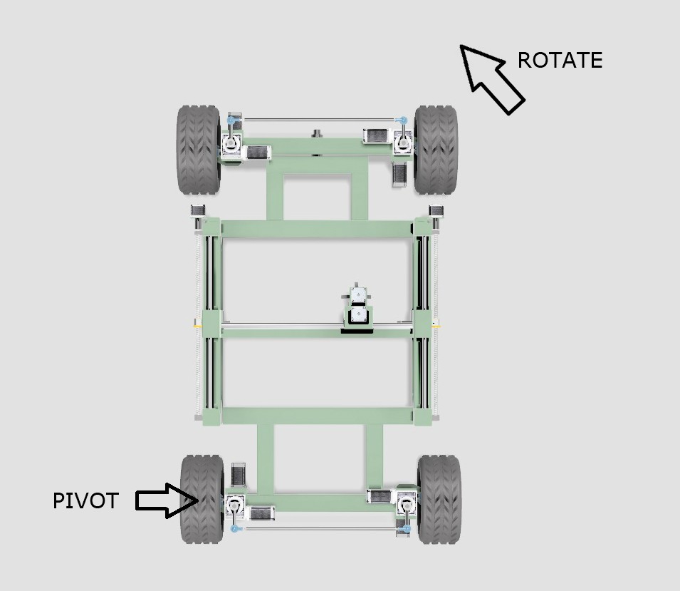
01/23/2018 at 10:44 • 0 commentsIf the WEEDINATOR is navigating a turn and has it's inside wheel at 45 degrees, the outside wheel is NOT 45 degrees, it's more like 30 degrees. Also, the inside wheel may be turning at 1 km/hour, but the outside wheel will be significantly faster, more like 1.35 km/hour.
![]()
When working out the geometry, a few assumptions are made:
- The chassis will pivot about one of the back wheels as shown in the diagram above.
- The effective centre of the pivot circle will move along a line extended from the centres of the two back wheels, depending on the angle of turn.
- The geometry will take the form of a sine curve.
![]()
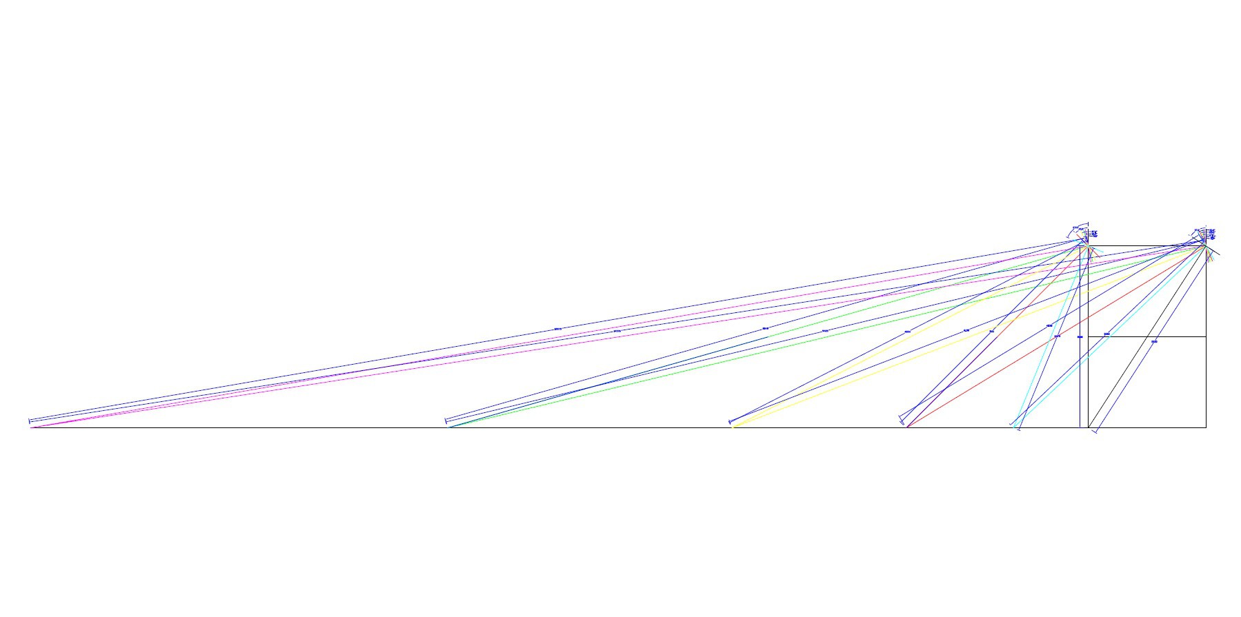
A full scale drawing was made of the WEEDINATOR front wheels and chassis with 8 different permutations of inside wheel angle between 0 and 90 degrees and the respective turn centres were mapped out as shown in the drawings above.
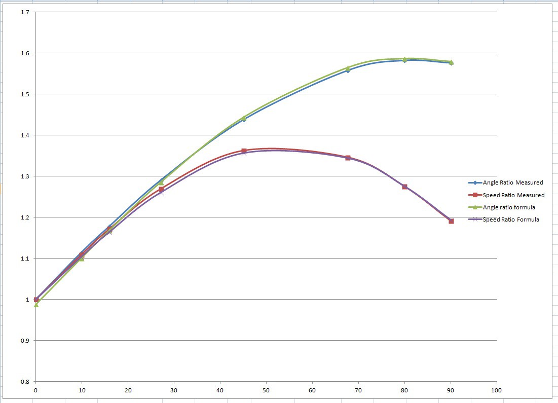
The effective radii were measured from the drawing and plotted on a graph in Microsoft Excel.
Two graphs were produced, one of the ratio of the left and right front wheel axles and another for the ratio of the two radii for each particular turn angle.
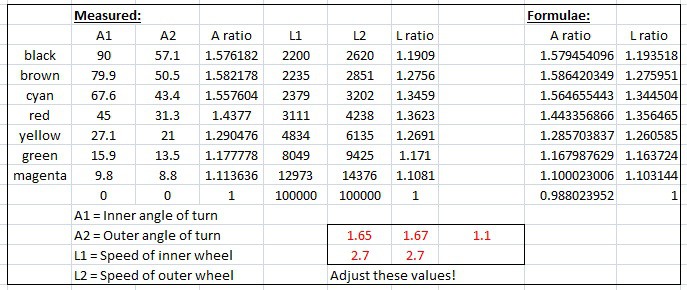
I then 'fudged' up some formulae to mimic the empirical results based on a sine curve. One of the fudgings looks like this:
speedRatio= (sin(inner*1.65*pi/180)+2.7)/2.7; // inner is the inner turn angle.
The curves were fudged by changing the values shown in red in the excel file until the curves fitted together.
![]()
![]()
Full details and downloadable files are shown here:
https://www.instructables.com/id/WEEDINATOR-Part-4-Differential-Steering-Geometry-C/
-
Weedinator does a 3 Point Turn
01/17/2018 at 18:07 • 0 comments -
Maiden Voyage of the Weedinator
01/15/2018 at 13:23 • 2 comments -
More GNSS Tests
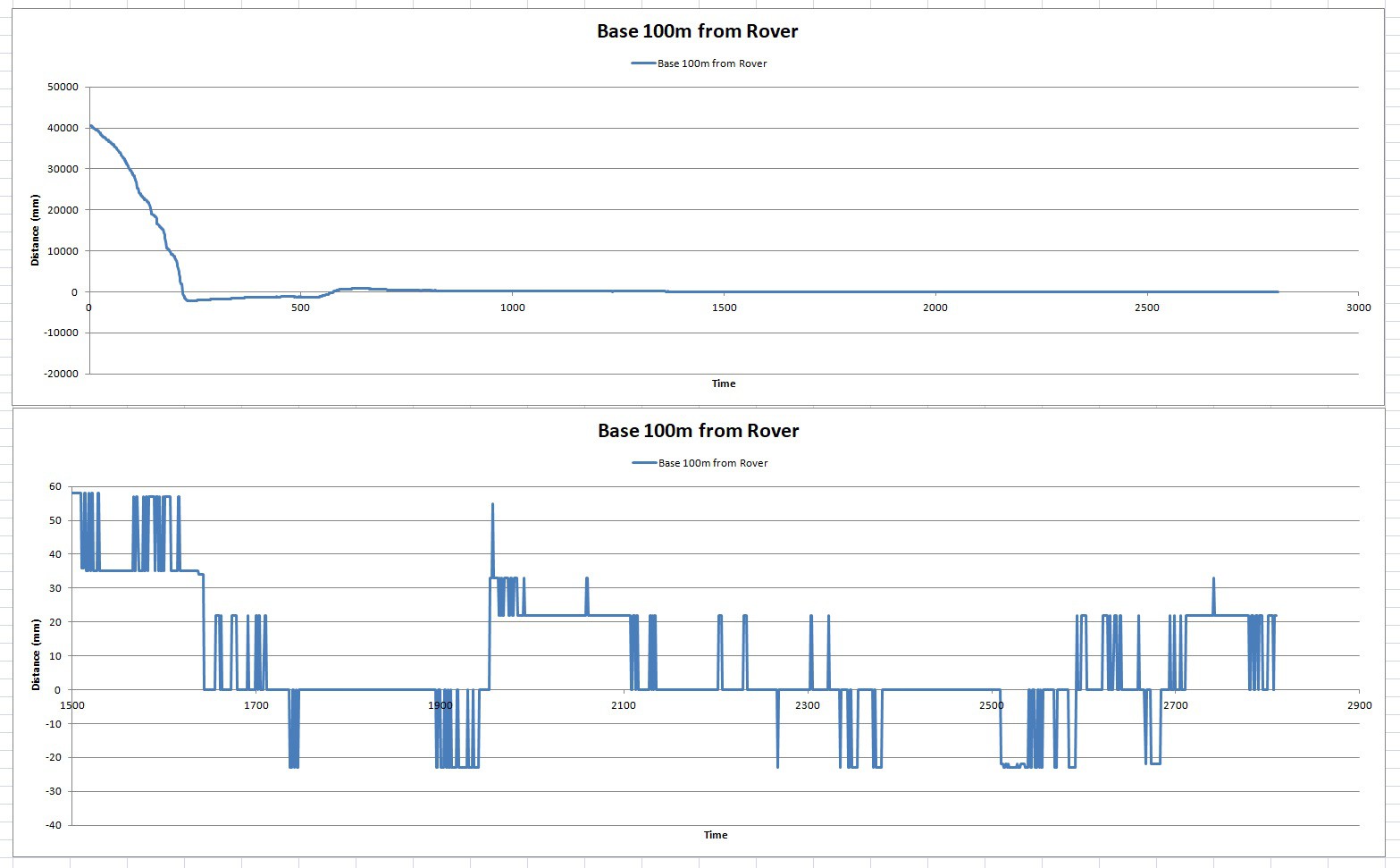
12/20/2017 at 19:02 • 0 comments![]() You really can't have enough graphs in a project and testing the Sat Nav always produces a shed load of data. This time the Base and Rover are separated by 100 m to see what error, if any, is added. I can't decern any noticeable additional error at all. The 'Fix' was obtained at about 1650 on the horizontal and from then on the total error was pretty much 40 mm, as before :)
You really can't have enough graphs in a project and testing the Sat Nav always produces a shed load of data. This time the Base and Rover are separated by 100 m to see what error, if any, is added. I can't decern any noticeable additional error at all. The 'Fix' was obtained at about 1650 on the horizontal and from then on the total error was pretty much 40 mm, as before :) -
Ublox Accuracy
12/13/2017 at 10:36 • 0 commentsI managed to hook up a datalogger to the Weedinator control board via I2C and get some idea of the Ublox M8M Satellite positioning performance:
![]() On 'Cold Start', the module started off with lots of error and gradually the error became reduced until, after about 2 hours, it got a RTK fix between rover and base (shown as the red cross). During that 2 hour period, the base module is continually building up and updating an average value for latitude and longitude and after the pre-programmed time interval decides that it has got a good fix.
On 'Cold Start', the module started off with lots of error and gradually the error became reduced until, after about 2 hours, it got a RTK fix between rover and base (shown as the red cross). During that 2 hour period, the base module is continually building up and updating an average value for latitude and longitude and after the pre-programmed time interval decides that it has got a good fix.The next 2 graphs shows behaviour after a 'Hot start' where the base module has already calculated a good average. The top graph is over a 200 minute period and occasionally the fix is lost and the rover sends a NMEA message to the Weedinator that the fix has temporarily become unreliable.
![]() The lower graph is a 'zoom in' on the red box in the top graph and shows a good representative snap shot of the Ublox performance, with total deviation of 40 mm, with is good enough to guide the Weedinator to it's loacation, but possibly not good enough to cultivate the soil around individual plants?
The lower graph is a 'zoom in' on the red box in the top graph and shows a good representative snap shot of the Ublox performance, with total deviation of 40 mm, with is good enough to guide the Weedinator to it's loacation, but possibly not good enough to cultivate the soil around individual plants? -
Data Flow Diagram
12/11/2017 at 14:38 • 2 commentsI thought it would be interesting to map out how the data flows between the various modules:
![]()
The intention is to offload all of the control modules away from the Master, the Arduino Due, so that any timing issues can be avoided - some of the modules use multiple timers and interrupts which would conflict with each other if they were on the same MCU.
The Spark fun compass would only work on the Due itself and even then only through the serial port rather than I2C, which would have been preferred. Coincidentally, it's the only module that is not giving reliable results, so I figure it will need to be replaced at some stage.
Good news is that everything else works nicely and the data flows around the modules without any glitches. Especially remarkable is the Ublox C94 M8M, which is working much better than previous tests suggested. I'm going to try and do some long term data logging to greater assess it's performance, but currently it seems to be giving reliable fixes within a total deviation of 40 mm (20mm either sides of centre) about 95% of the time. (Must brush up on some statistical analysis maths).
-
3D Animations
12/06/2017 at 12:54 • 0 comments -
Bearing and Distance Operational
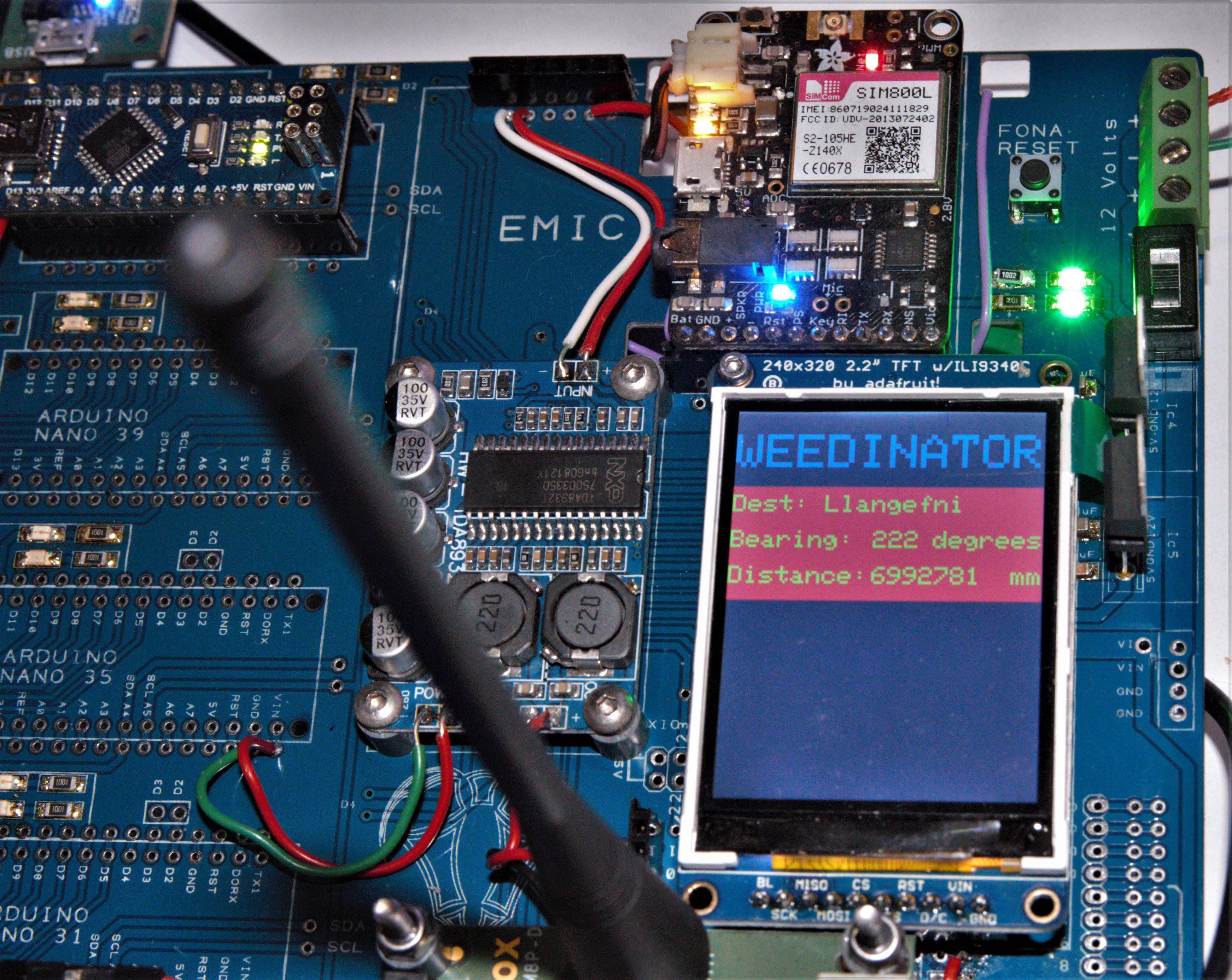
12/03/2017 at 16:52 • 0 commentsThe Ublox C94 M8P has been configured to provide a heading and distance to my nearest town :
![]() Obviously I don't want the machine to actually go there - it's just a test to see if I'm getting correct results.
Obviously I don't want the machine to actually go there - it's just a test to see if I'm getting correct results.The software used is by SlashDevin - NeoGPS. Special attention was required to get the baud rate selected properly for all functions of the Ublox to work (19200), most importantly it's ability to get a fix between the Rover and Base station. The base just sits on a pole somewhere and using the two as a pair error correction due to atmospheric anomalies can be achieved.
-
Control Panel Getting Populated
12/01/2017 at 12:53 • 2 comments![]()
The PCBs arrived from Elecrow, China, and immediately became populated by a vast array of SMT LEDs, Zero ohm jumpers and some capacitors for the linear voltage regulators. Strangely, at least so far, there are no mistakes in the PCB design!
The overall design is based on a master and slaves system with the master being and Arduino Due and most of the slaves Arduino Nanos, all communicating through the I2C protocol. The Ublox GPS Rover module (lower right) spits out NMEA satellite data every second to be captured through the serial1 port on a "Pro Micro" (not shown). The data can then be processed into headings and distances and accessed whenever the Master requires it by polling the slave via I2C.
Some of the components on the board are 3v and others 5v so care has been taken to make sure the I2C bus from the Due to the Nanos goes through a level shifter, which is bolted onto the back of the PCB. The Ublox is 3v and outputs serial directly to the 3v Pro micro, which in turn connects directly to the 3v Due via the I2C bus.
My I2C code has been vastly improved by turning all the data into characters, which are much easier to manipulate on the 8 bit system than trying to manipulate integers and floats directly. Here's a snippet of the Master code:
void loop(void)
{
  characterCompile();
  introText();
  Wire1.beginTransmission(26); // transmit to device #26
  Wire1.write("Important number: ");        // sends 21 bytes
  Wire1.write(url);              // sends one byte
  //delay(100);
  Wire1.endTransmission();    // stop transmitting
  x++;
  delay(100);
}
void characterCompile()
{
///////////////////////////////////////////////////////////////////////////////////////////////////////////////////////        BME280Temperature
// This is where the data is compiled into a character ....
  dataString =  initiator + x ;
  int n = dataString.length();
//  Serial.print("Data string to send:     ");Serial.println(dataString);
//  Serial.print("Size of string:  ");Serial.println(n);
  // Builds the url character:
      for (int aa=0;aa<=n;aa++)
      {
          url[aa] = dataString[aa];
      }
  Serial.print("Character data to send:  ");Serial.println(url);
  Serial.println("");
///////////////////////////////////////////////////////////////////////////////////////////////////////////////////////
}
And here's the Slave code:
#include <Wire.h>
long result=0;
char c[100];
String y;
String w;
String a;
String b;
String triggerWord = "Important";

void setup() {
  Wire.begin(26);                 // join i2c bus with address #8
  Wire.onReceive(receiveEvent);   // register event
  Serial.begin(115200);           // start serial for output
}
void loop()
{
  delay(100);
}
// function that executes whenever data is received from master
// this function is registered as an event, see setup()
void receiveEvent(int howMany)
{
  int i=0;
  y="";
  a="";
  b="";
  while ( Wire.available())
  {
    char c = Wire.read();     // receive byte as a character
    if (isAlpha(c))           // analyse c for letters
    {
      a=a+c;
      if (a==triggerWord)
      {
        b=a;
        Serial.print("Trigger word detected!: ");Serial.println(b);
      }
    }
    if (isDigit(c))       // analyse c for numerical digit
    {
      y=y+c;            // string = string + character
    }
    i++;
  }
    w=y;                  // string w = string y
    if (b==triggerWord)
    {
      result=(w).toInt();
      Serial.print("Resultant integer: ");Serial.println(result);
    }
    if (b!=triggerWord)
    {
      Serial.println("Nothing detected");
    }
    Serial.println("");
}
There's still quite a lot of work to do, for example setting up the GPRS link to a database on the interweb, but nothing too tricky. The only aspect of the project that I have not previous experience is the object recognition ....... That's a challenge to look forward to!
WEEDINATOR 2017
An autonomous roving CNC weeding/cultivating machine guided by GPS and coloured markers.
 You really can't have enough graphs in a project and testing the Sat Nav always produces a shed load of data. This time the Base and Rover are separated by 100 m to see what error, if any, is added. I can't decern any noticeable additional error at all. The 'Fix' was obtained at about 1650 on the horizontal and from then on the total error was pretty much 40 mm, as before :)
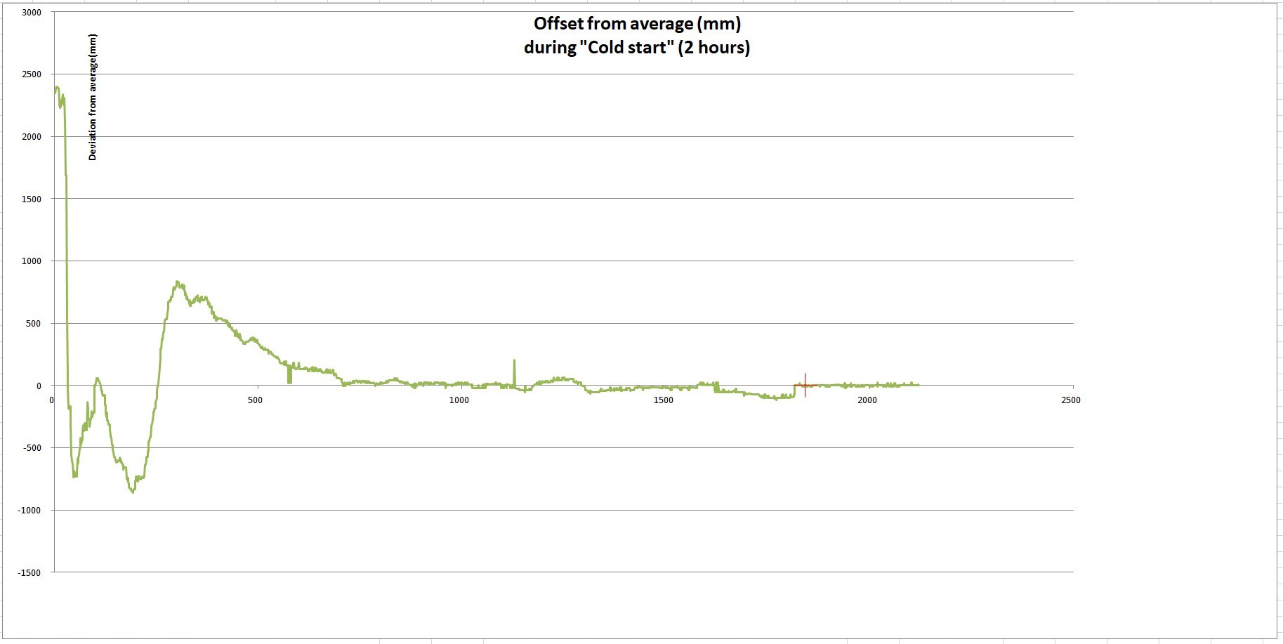 On 'Cold Start', the module started off with lots of error and gradually the error became reduced until, after about 2 hours, it got a RTK fix between rover and base (shown as the red cross). During that 2 hour period, the base module is continually building up and updating an average value for latitude and longitude and after the pre-programmed time interval decides that it has got a good fix.
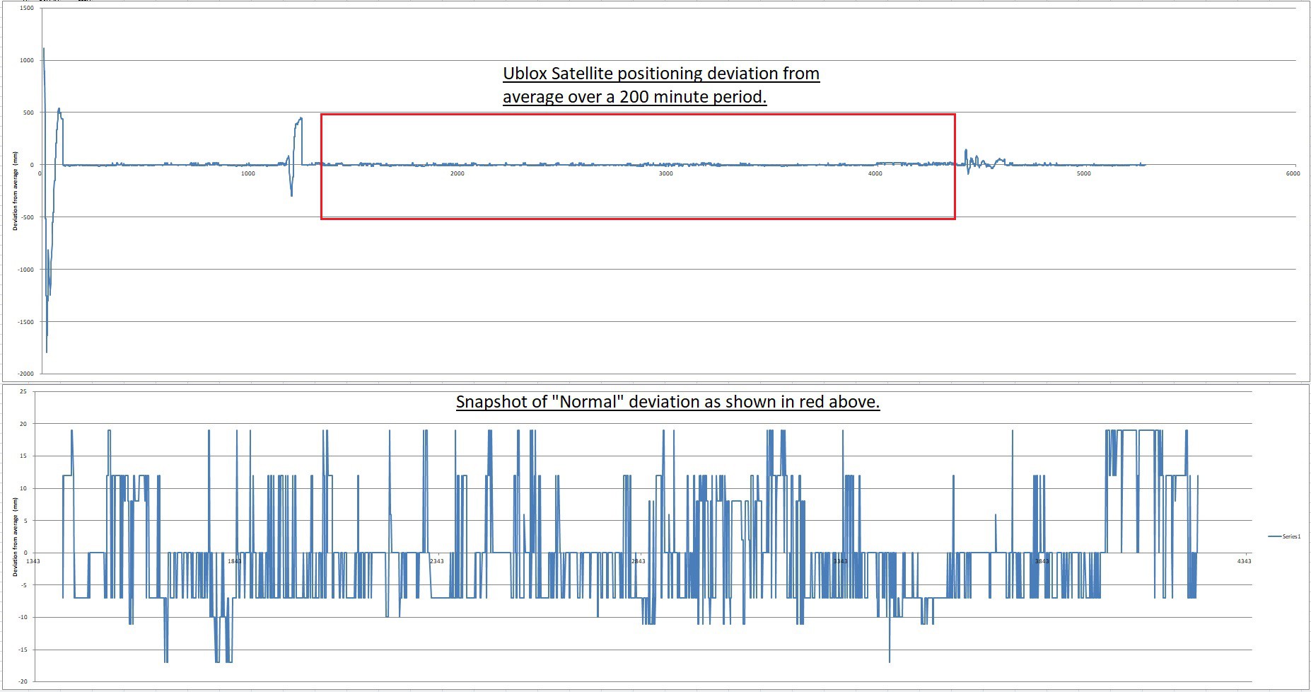 The lower graph is a 'zoom in' on the red box in the top graph and shows a good representative snap shot of the Ublox performance, with total deviation of 40 mm, with is good enough to guide the Weedinator to it's loacation, but possibly not good enough to cultivate the soil around individual plants?
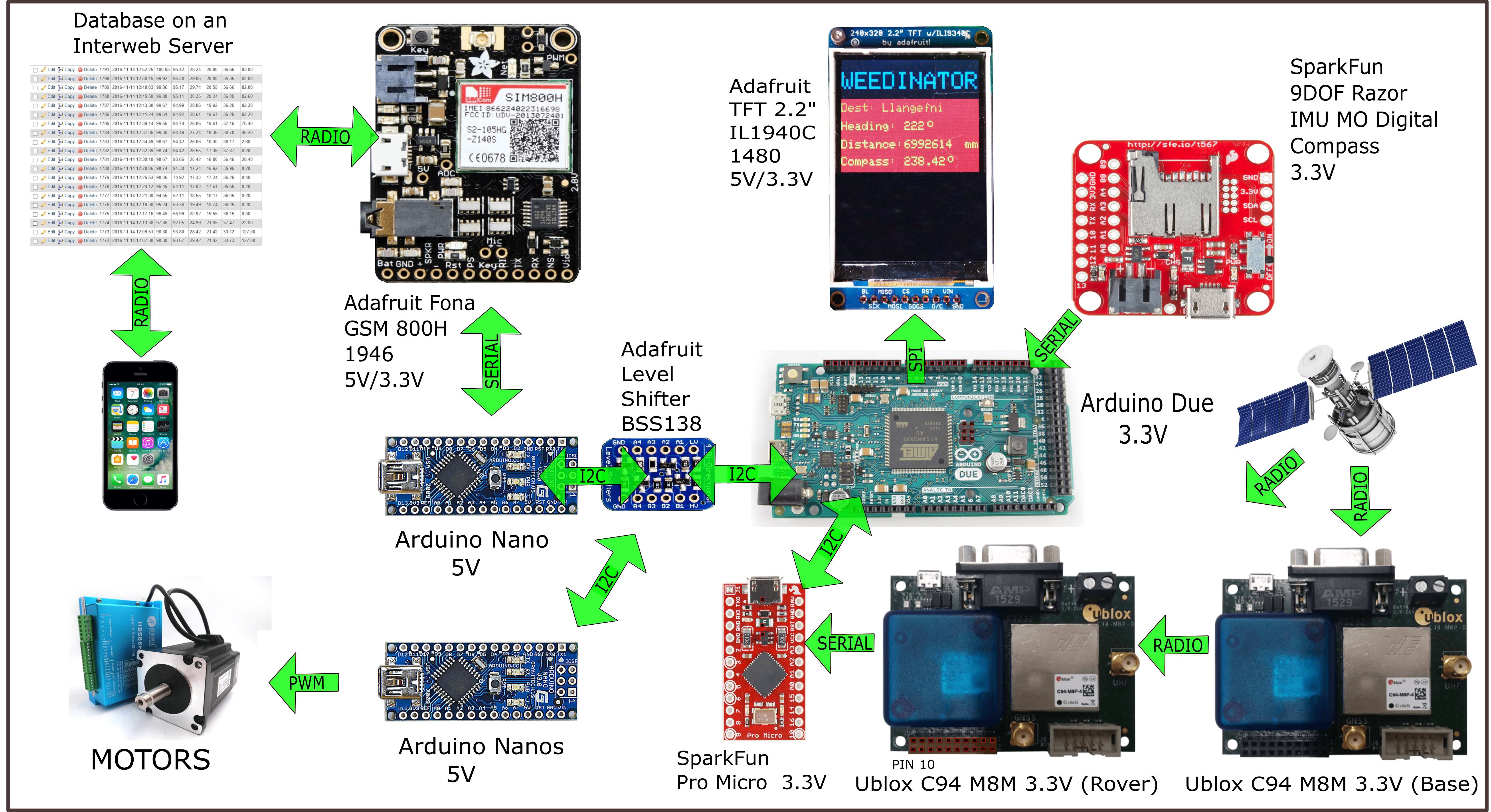
 Obviously I don't want the machine to actually go there - it's just a test to see if I'm getting correct results.