Chris.deerleg
-
Beam Deflection
11/29/2017 at 22:18 • 0 comments![]()
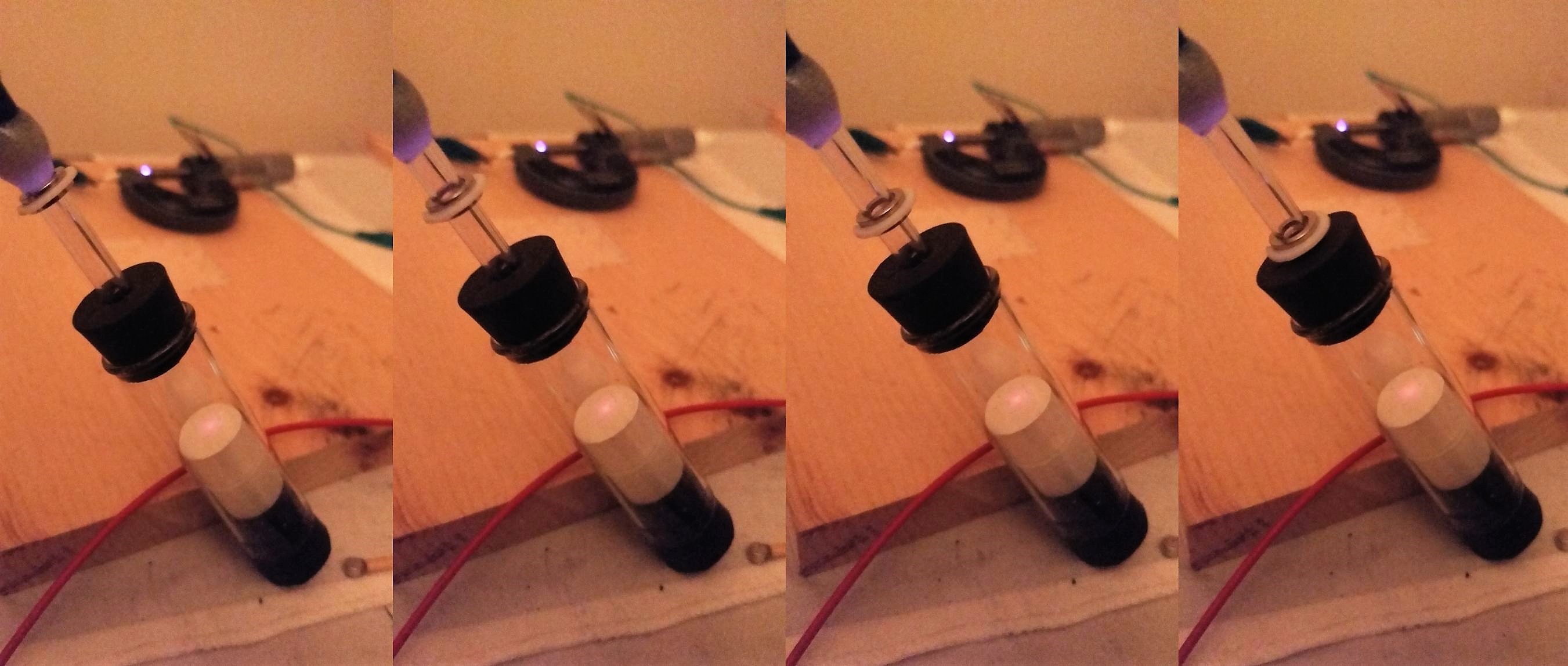
The images above show the movement of the electron beam. It is necessary to apply two magnetic fields. One magnetic field is much faster as the other. The fast one causes the red line and the slower one causes a rotation of the line.
![]()
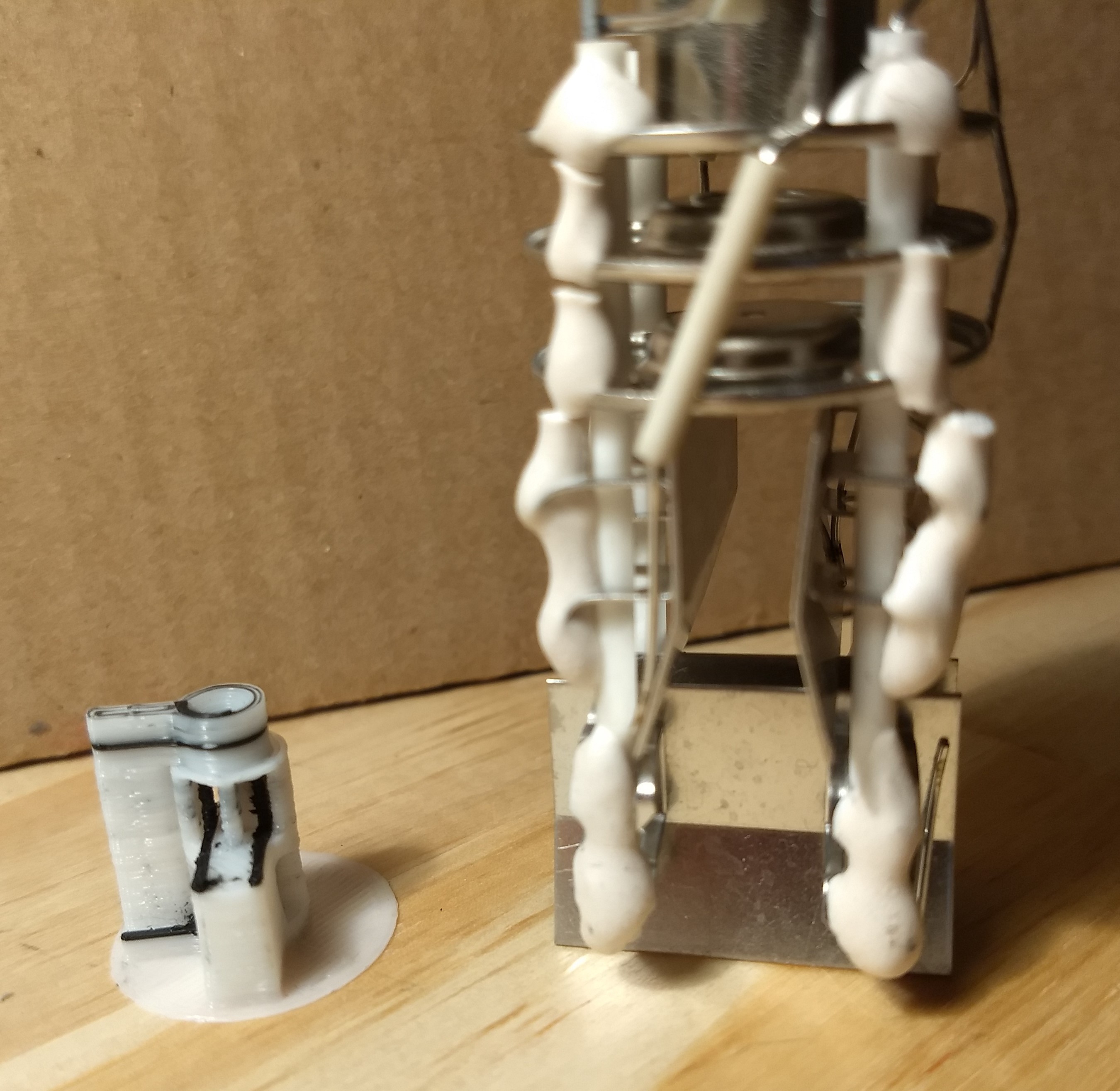
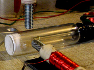
The image above shows the deflection system of a scope's CRT . On the right side is a original one and on the left side is the version out of the 3D printer. The black plastic is conductive and the white plastic build a isolation. The approach from a scope doesn't worked for me, because of the high acceleration voltage. The voltage at the deflector plates should be in the same rage as the acceleration voltage.
In the my CRT tube is the accelerations voltage about 3000V and the plasma ignition starts at approx. 400V. Therefor a plasma appear if the accelerations voltage is applied to the deflector plates. This plasma is a electron source and make it impossible to have a sharp electron beam. The right approach for the deflection is similar as the deflection in a TV tube. Two magnetic fields applied for different directions make it possible to deflect the beam.
![]()
DIY CRT tube by Nyle Steiner K7NS Oct 2007 The image above shows the set up from Nyle Steiner who demonstrated on his homage how he made it.
-
Magnetic Lens
11/06/2017 at 23:11 • 0 comments![]()
I was able to find some magnets (Ring-Magnets) that have the right shape to work as a magnetic lens. On the image above is the magnet arrangement show which produced the smallest and brightest spot. Two magnets are close together. The distance between the both magnets is approximately 1mm. The third magnet has a distance of approximate 35 mm to the double magnet.
![]()
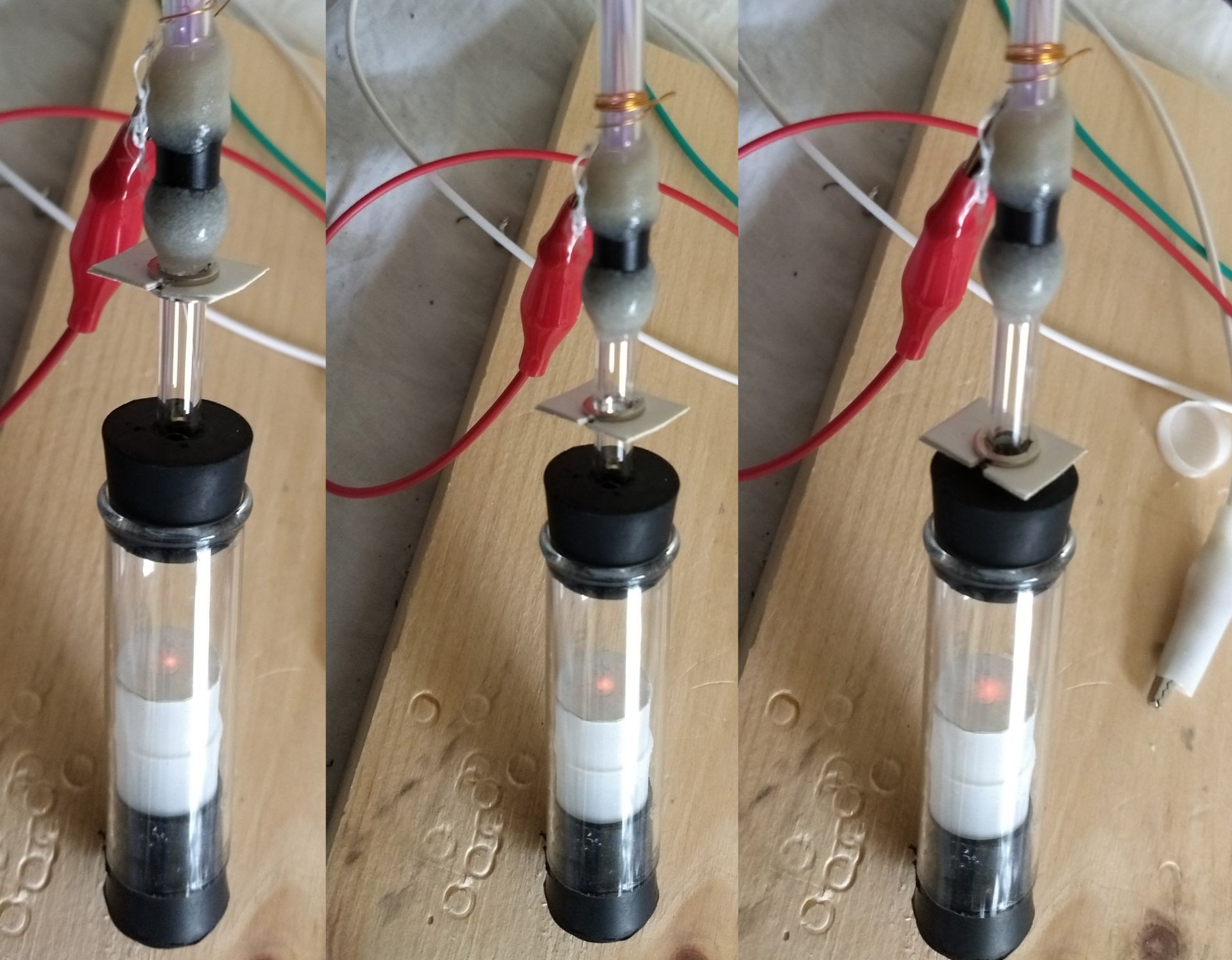
The small red spot is approximately 20 mm away from the third magnet. On the image above is shown how the focus is changed by moving the double magnet. From left to right moves the double magnet closer to the third magnet. The consequence is that the red spot becomes more blurred.
![]()
I got a sharper and brighter spot. On the image above from left to right the dual magnet move from up to down.
![]()
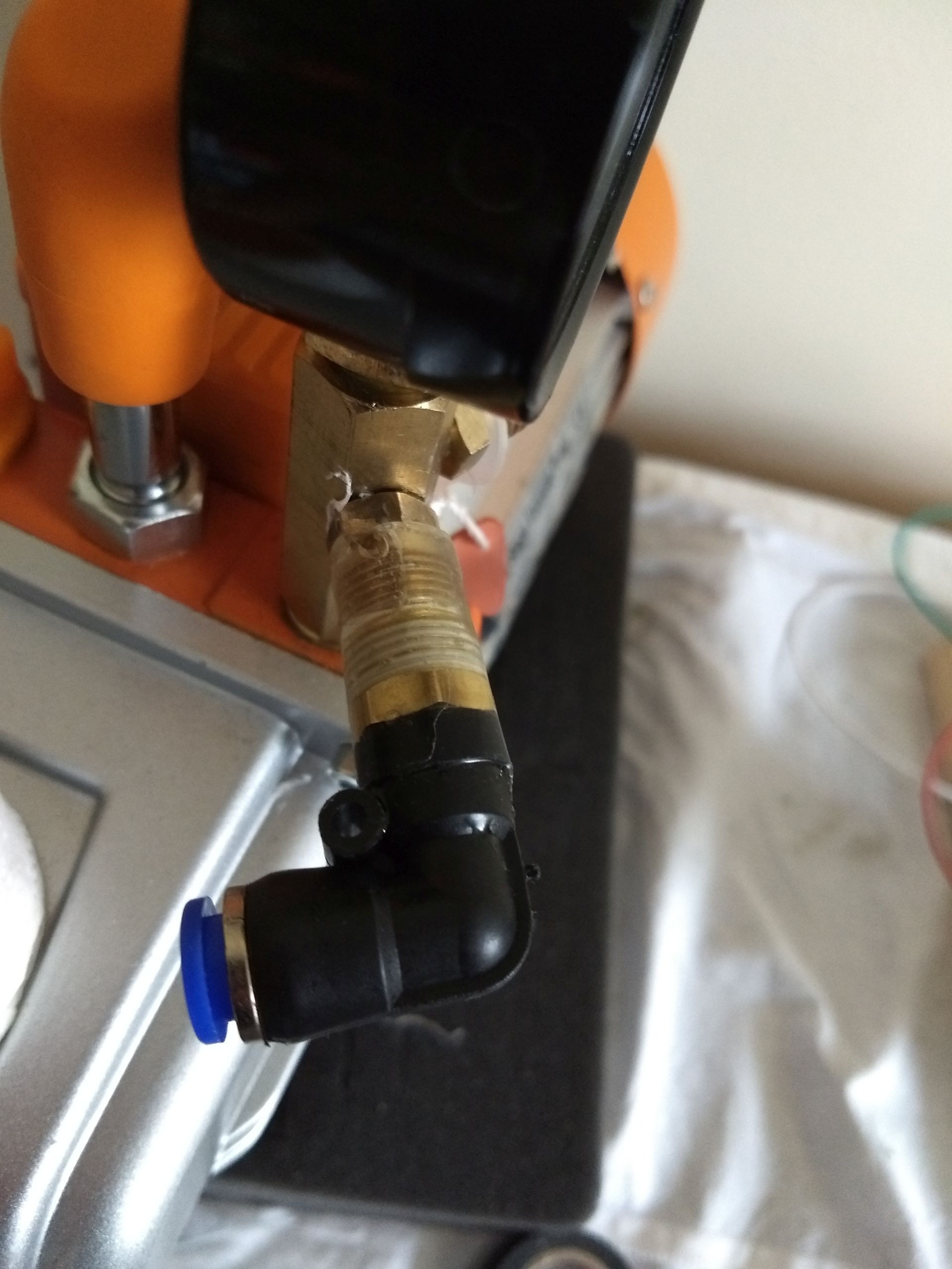
The reason for the blurry spot was a uptight connection form the tubing to the vacuum pump. I glued a push connector with epoxy direct to the pump. An now it seams to work.
-
Vacuum Chamber
10/20/2017 at 16:17 • 0 comments![]()
Now I know one reason more why I had trouble to see a electron beam. The vacuum was too bad.
I figured out that electron beam disappear if I place a wire with 0.3mm between the rubber plug and the gals wall.
Further I figured out that by changing the spark gap from the anode side to the cathode side I could remove the aluminum strip from the bottom of the glass. Also I changed the screen material from glowing in the dark powder to pure zinc sulfide.
-
Electron Gun
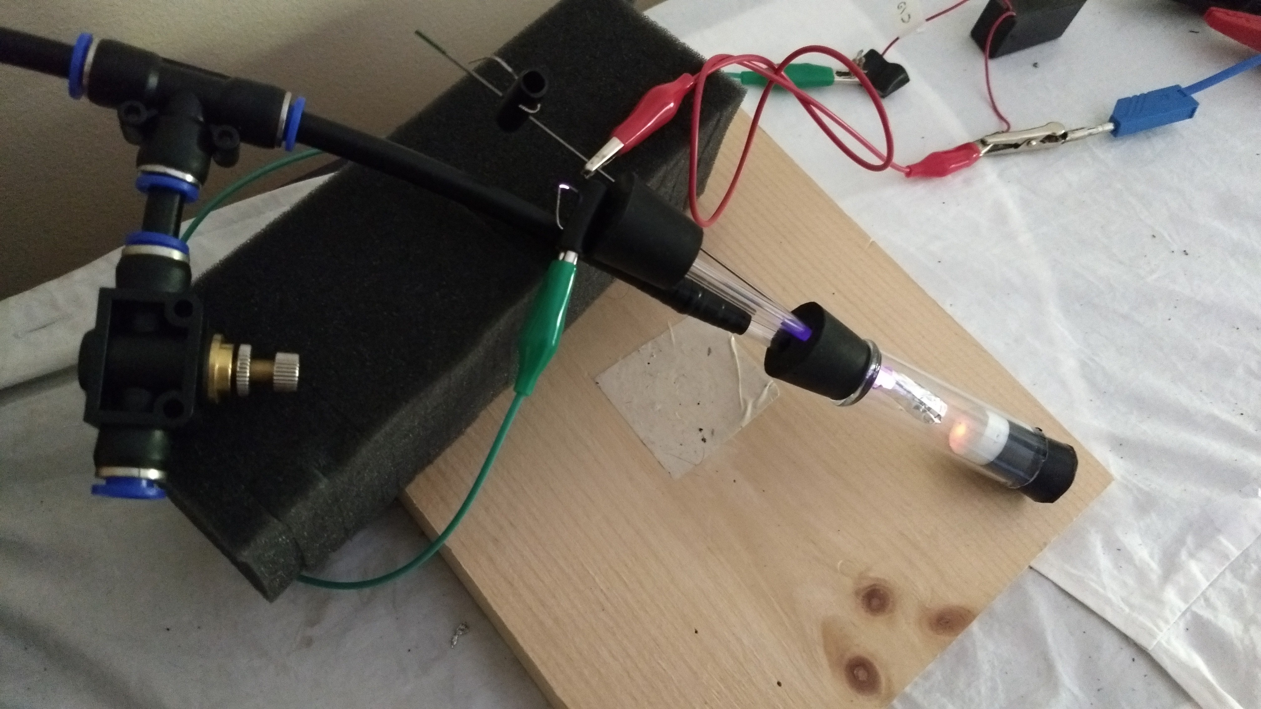
09/25/2017 at 22:05 • 0 comments![]() Whole setup
Whole setupI needed one month. However I saw my first self made electron beam. I have had to over come multiple challenges.
![]()
pure zinc sulfide glows red by electron detection
First of all I wasn't sure what the right material was to make an electron beam visible. I thought that I needed a type of phosphor because the most web pages speak about a phosphor screen for the visualization of an election beam. Luckily, I found some pages that mentioned zinc sulfide is the right material.
![]() glowing in the dark powder also called zinc sulfide with copper (ZnS:Cu) glows green A very common and good available mixture is zinc sulfide with copper (ZnS:Cu) or also called glowing in the dark powder. It has a long after glow effect even on light. To build a screen mix zinc sulfide powder with water and a little bit of glue and let it dry on the bottom of the chamber. I recommend glue because without it the screen isn't stable. Otherwise it could happen that the screen blows away by returning air when the vacuum is released.
glowing in the dark powder also called zinc sulfide with copper (ZnS:Cu) glows green A very common and good available mixture is zinc sulfide with copper (ZnS:Cu) or also called glowing in the dark powder. It has a long after glow effect even on light. To build a screen mix zinc sulfide powder with water and a little bit of glue and let it dry on the bottom of the chamber. I recommend glue because without it the screen isn't stable. Otherwise it could happen that the screen blows away by returning air when the vacuum is released.
![]() glowing caused by light
glowing caused by lightUnfortunately, I thought a long time that I see electrons even if I saw just light. The effect that the spot didn’t move either by an electrical or by a magnetical field made me distrustful.
![]()
Spark gap
The second main issue was that the voltage collapses from 6kV to 500V by applying it to the plasma tube. Whereas the high voltage is required to accelerate the elections enough to build a beam. Maybe the reason that the voltage collapsed was a non-suitable vacuum or not strong enough power supply. Anyway, I solved this issue by including a spark gap in the circuit of the plasma tube. This spark gap let the voltage rise until it's big enough to create a spark. Once the spark appears, the high volt is applied and accelerate the electrons properly. The spark gap is made by a piece of the LDPE vacuum tube and two spikes.
![]() Discharge rings made of aluminum foil
Discharge rings made of aluminum foilA third issue was that the out part of the tube need a anode to discharge the chamber. I putted just a little bit of aluminum foil around the chamber and connected it to the anode.
The video show the whole set-up and further more what happens if
- The Discharge ring isn’t connected to the anode?
- How adjust the voltage?
- What happens without a spark gap?
- What happens with a wrong polarity?
- What do the plasma in a magnetic field?
-
HV Supply
08/02/2017 at 21:02 • 0 comments![]()
For my first experiments I use a 7kV china high voltage supply. (the black box on the right top). To get a impression of the capabilities of the HV Supply. I build a 200Meg Ohm voltage divider to measure the the voltage. I putted the resistor to connect the multi meter in the middle of the divider, just in case of a short circuit. The voltage divider has a ratio of 2001 = (200M+0.1M) / 0.1M. Each voltage on the multi meter multiplied with 2001 is the voltage over the voltage divider .
![]() The image above shows the test setup. The variable resistor RL I realized severl 10Meg Ohm resistors connected parallel.
The image above shows the test setup. The variable resistor RL I realized severl 10Meg Ohm resistors connected parallel. ![]()
The table above shows the measured values.
![]()
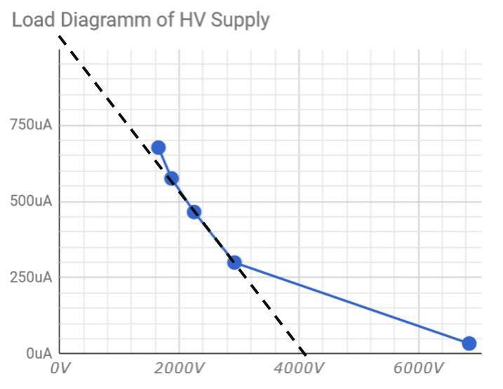
The diagram above show the voltage and the current of the HV supply. The calculation of the internal resistor Ri is shown below.
-
Vacuum Chamber
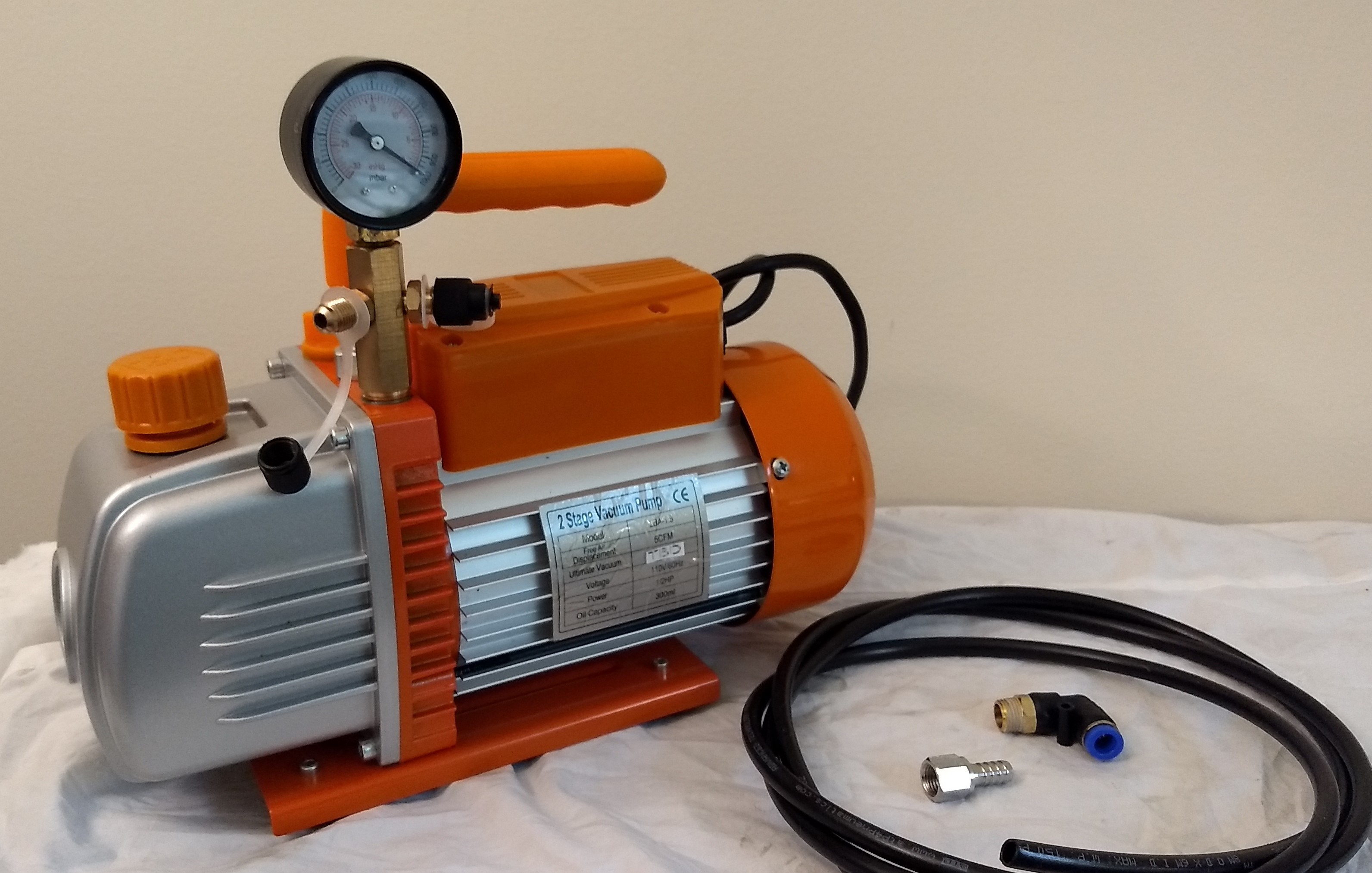
08/01/2017 at 19:40 • 0 comments![]() I got my vacuum pump and started to build the vacuum chamber.
I got my vacuum pump and started to build the vacuum chamber. ![]()
I started with a marmalade glas, LDPE pressure tube and a quick connector.
![]()
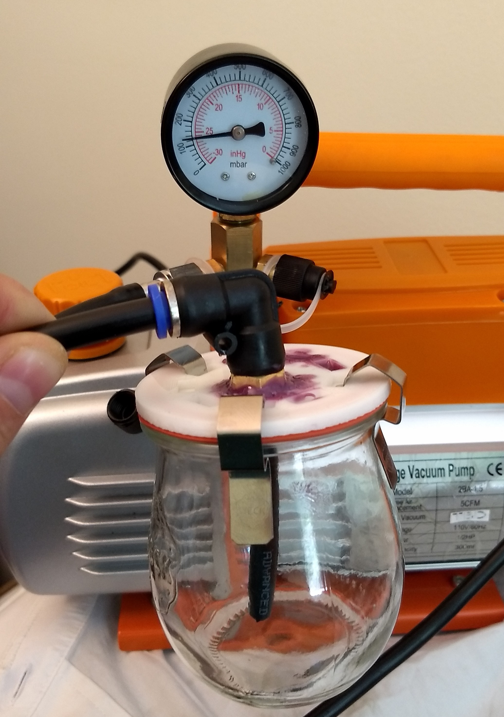
With the first printed vacuum chamber cap, the achievable vacuum was quite bad with 120mBar.
![]()
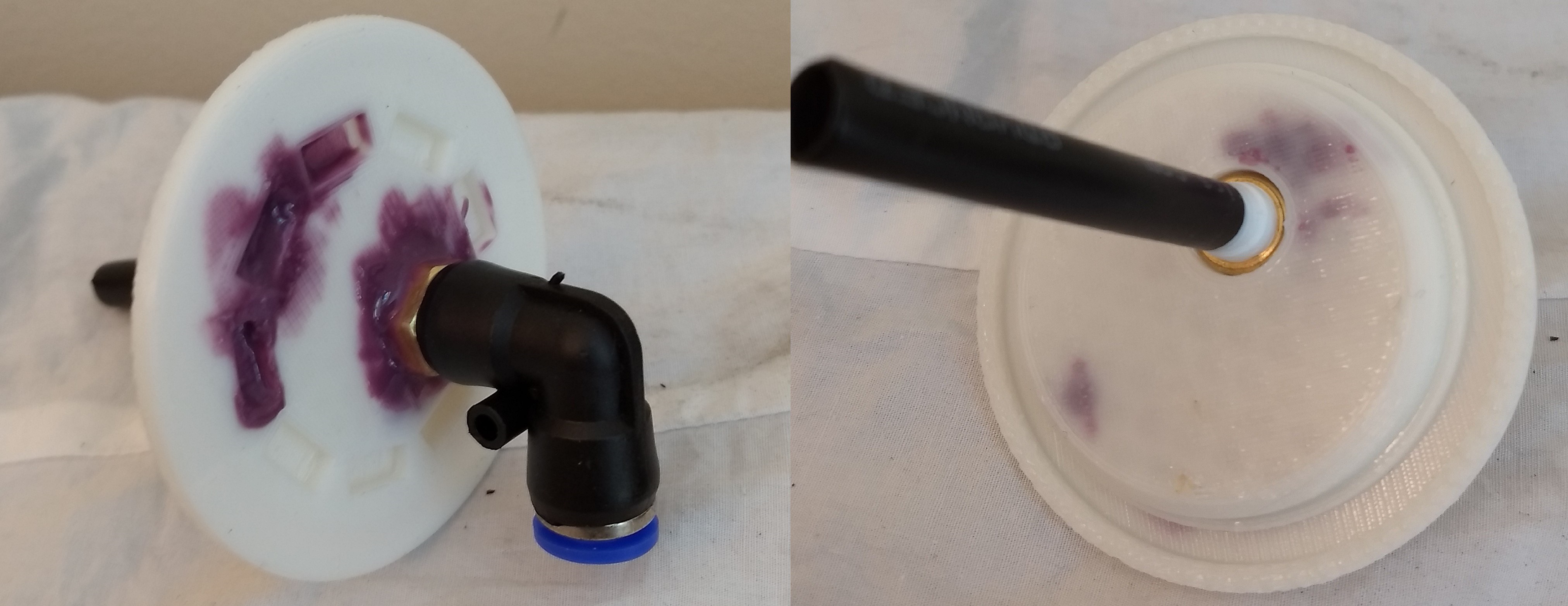
I putted colored glue on the cap, closed the vacuum chamber and started the vacuum pump. After a while I could see on the bottom of the cap the colored glue. Therefor the root cause for the bad vacuum were some small gaps in the printed cap.
![]()
Above you can see the CAD model of the cap. In this version the quick connector is replaced by a barb connection, similar to the connection between the vacuum pump and the tube.
The video above shows an accelerated print, it visible that the filling factor is 100% of the print.
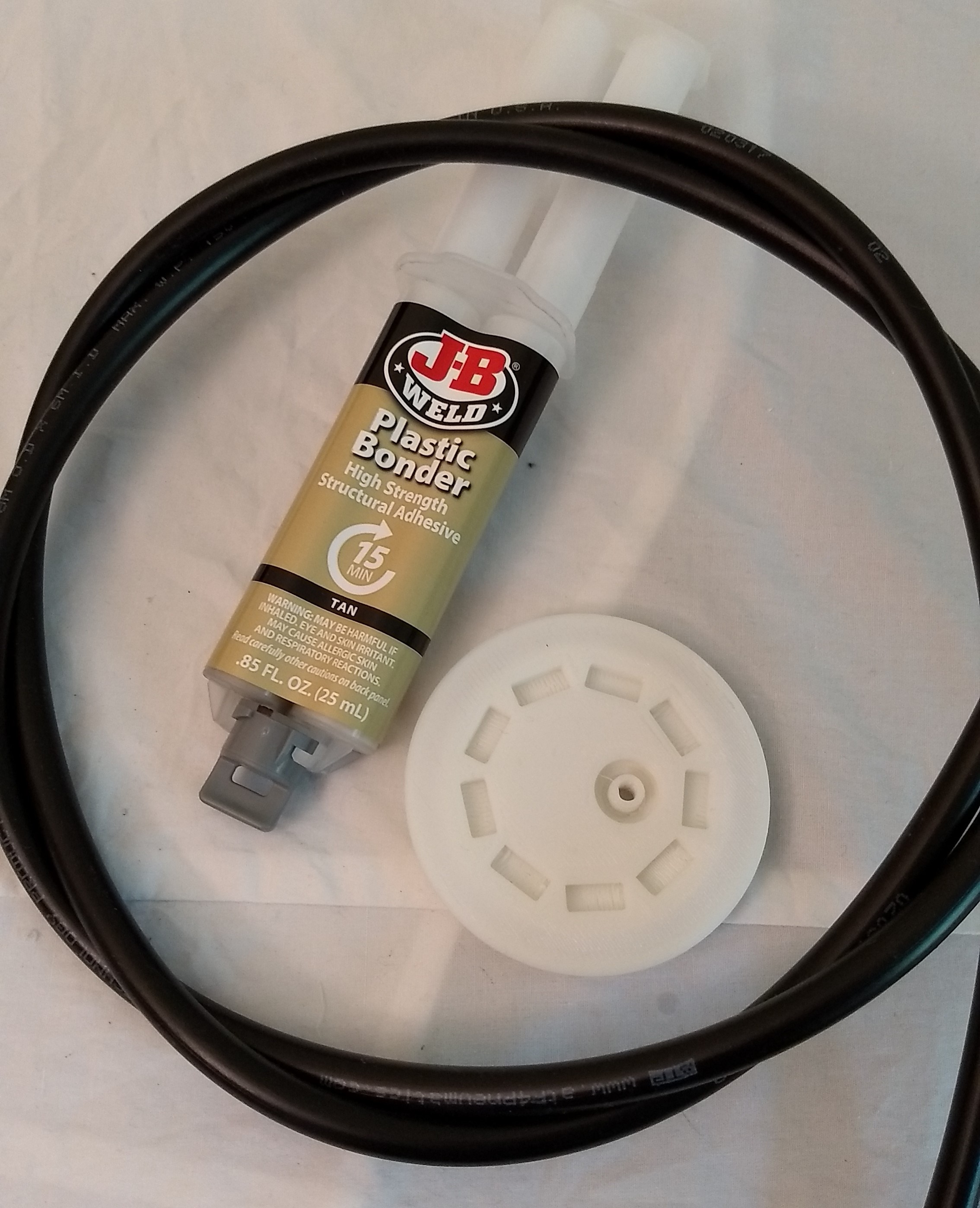
![]() To get a strong connection between the cap made of PLA and the tube made of LDPE I used a special 2K glue. The special at this glue is, that it is suitable for PE. The most other 2K glues are explicit not recommended for PE or PP gluing.
To get a strong connection between the cap made of PLA and the tube made of LDPE I used a special 2K glue. The special at this glue is, that it is suitable for PE. The most other 2K glues are explicit not recommended for PE or PP gluing.![]()
The image above proofs it, now all looks tight.
-
Femm 4.2 magnetic simulation runs
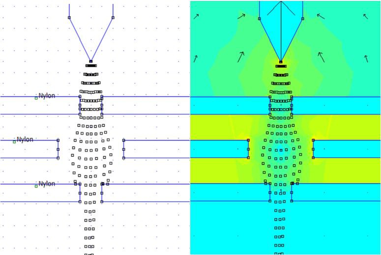
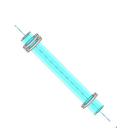
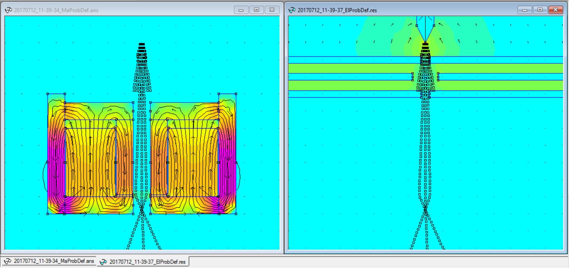
07/13/2017 at 01:28 • 0 comments![]() Today I included the pieces that the electrons interact with the magnetic field and it seems to work. The current version I uploaded on GitHub. One the image above on the right side is the electron source shown as I already described in the Last Log. One the left side is the magnet with a cage of iron shown. In the middle a little bit above of the crossing beams is a light green field visible. This field is the reason for crossing traces of the electrons.
Today I included the pieces that the electrons interact with the magnetic field and it seems to work. The current version I uploaded on GitHub. One the image above on the right side is the electron source shown as I already described in the Last Log. One the left side is the magnet with a cage of iron shown. In the middle a little bit above of the crossing beams is a light green field visible. This field is the reason for crossing traces of the electrons. ![]()
The principle why the electron change a direction in a magnetic field is a little bit more complex as in a electrical field. But I try it to explain. The electrons moves in the Y direction, because they are already accelerated by the electrical field. The movement in the Y direction with the magnetic field in X direction accelerate the electrons in Phi direction. The left hand rule is quite helpful. The thumb shows in the direction of the particle motion, the index finger shows in the direction of the field and the middle finger tells the direction of the acceleration of the particle. In the simulation the field in X-Axis is rotational symmetric. Therefore you can imagine that very time when the particle move a little bit you have to repeat the left hand rule and then you see that a circle come up. Now is clear why the electrons start to rotate on a orbit but not why the move in the X direction.
![]()
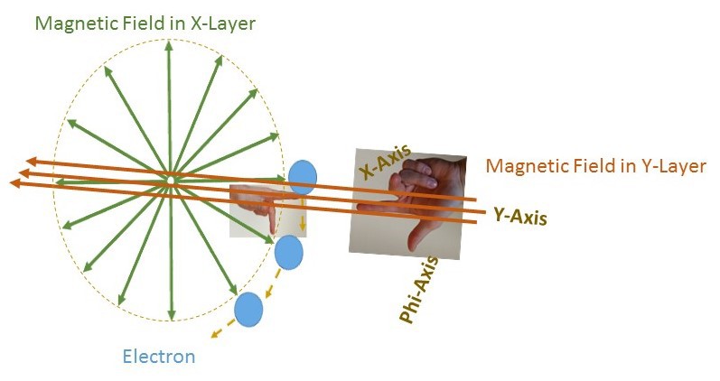
Let do the left hand rule for the magnetic field in Y direction. The thumb shows in the direction circular orbit of the electrons. The index finger shows in the Y direction of the magnetic field and tells that the electrons go on the X-Axis in the direction of the center.
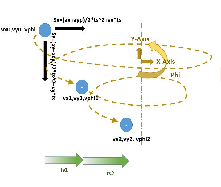
![]() In one of my previous logs, I explained how I calculate the position (Position Calculation). For the inclusion of the field in the position calculation I added the acceleration from the magnetic field to the acceleration of the electrical field. For this I need a additional variable vphi what contains the circular speed of the particle.
In one of my previous logs, I explained how I calculate the position (Position Calculation). For the inclusion of the field in the position calculation I added the acceleration from the magnetic field to the acceleration of the electrical field. For this I need a additional variable vphi what contains the circular speed of the particle. -
Femm 4.2 magnetic simulation tool interim update
07/06/2017 at 22:54 • 0 comments![]()
![]()
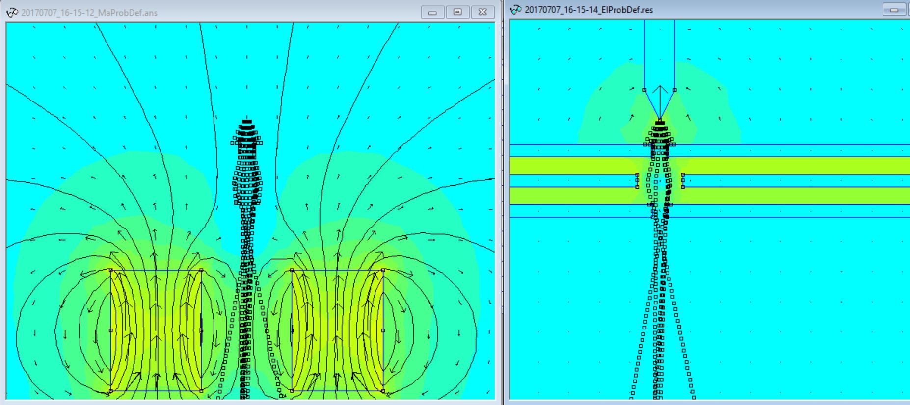
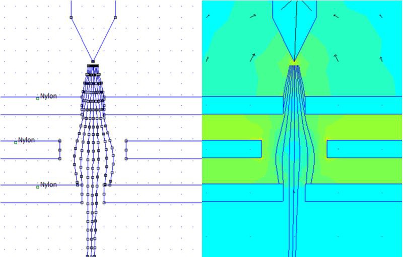
In last month I optimized how both parts of the simulation (electrical, magnetical) interact. But it is still one major piece of the simulation missing. May you can see it on the top left image. The particles are not response to the magnetic field. But the particles response to the electrical field, what you see on the top left image. One the left image you see a tip with -100 volt and the trace of the electrons. The particles are accelerated by the electrical field between the tip and the first plate. The first plate has a voltage of 0 volt. The plate in the middle has again -100 volt and the last one has again 0 volt. The voltage differences are the reason why the electron traces are bented. At the first plate at the edges you can see that if a electron touch a object it stops. The electrons cross both parts of the simulation the electrical and the magnetical. Therefore you see the traces on the left and the right side of the image
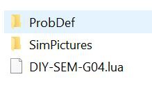
The current version I uploaded on Github. to run the simulation you need the FEMM 4.2. In the folder where the DIY-SEM-G04 is located you have to create two folder. Probdef for the simulation and SimPictures for the storage of the images. Without these folders you get a error.![]()
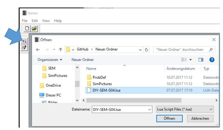
to run the simulation open FEMM 4.2 click on the button, select the file and that it. Now the Simulation need some minutes and after that you find the images in the SimPictures folder.![]()
![]()
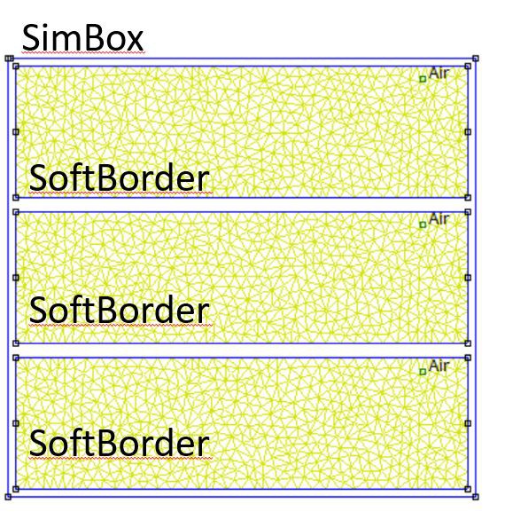
For writing the code I use Notepad++. Lets do a quick walk through the code. At the beginning a SimBox needs to create. With the "Ma" is a magnetical and with a "El" is a electrical simulation box created. As next a softBorder needs to create.
![]()
The concept of the soft borders is that this give you the opportunity to separate part from each other. The particles can cross the soft borders but not the SimBox. If a particle touch the SimBox it stops. In the example code the size of the SimBox and the Softborder is equal therefore it appear only one box.
With the lines ... :Part(...) the objects are placed.
![]()
All objects are base on a pentagon. The parameters are
- H1 H2: Height
- W1 W2: Wide
- Turn: rotation in grade about the cente
- Posx Posy: Postion of the center
- Mat: Material of the object
- Volt or Polari: Voltage if the object is in a electrical simulation or the polarity in grade of the magnet if the object is in a magnetical simulation
With the lines ... :solve() are the magnetic and electrical fields are calculated. Afterwards the start point of the particles is defined with the line Particle:new(Sim,Sim,x1,y1,x2,y2,amount,step). The variable Sim contains which fields shall apply to the particles. The variables x,1y1,x2,y2 are the start and end points of a line on which the particles are placed. The variable amount is number of particles which are placed . The variable step contains the information what is the expect step size for the particle (It is the parameter S). The unit is in meter therefore is a step size of 0.2mm = 0.0002 m.
With the function ... :move() calculates the next positions of the particle. This function is repeatedly because with each call is a distance of the size step calculated. In the example it is called 100 times therefore the particles can travel 20mm=100*0.2mm.
![]()
The function ... :trace() bring the traces of the particles in the simulation see on the left side. To get a nice colorfully image the ... :solve() function has to called again.
![]()
if the the ...:trace(1) is called instead of trace() then the points will be connected with blue lines. But careful if the traces of participles cross each other then no image can be created.
With the line ... :savePic(...) is a image stored in the folder "SimPictures". The Parameter of the savePic function are the following:
- POSX,POSY: the center of the image
- HEIGHT: the height of the image
- (if the value is to small the image looks strange)
- WIDTH: the width of the image
- (if the value is to small the image looks strange)
- Infos: a sting shown in the file name of the image
![]()
Above you can see the mesh for the field calculation. As finer the gird as preciser field calculation. To get a finer grid two groups of particles are used. The first group par1 moved through the field and creates traces. The rough field is shown on the left side. With the traces the field is calculated again. This fine field is shown on the right side. To just see the second group (par2) of particles the first group (par1) is removed with the function ... :DelTraces. After that the second group of paricles (par2) is created and moved through the field the windows are closed with the line closeWindows().
![]()
The animation above show the trace of a rough mesh and a voltage change -10V to -130of the middle plate.
![]()
The animation above show the trace of a fine mesh and a voltage change from -10V to -130Vof the middle plate.
-
Femm 4.2 magnetic simulation tool particle stop at collision
06/09/2017 at 19:24 • 0 comments![]()
I struggled a little bit to teach the particle to stop at a collision with a solid object. But now I did it. Above you can see the result. You see 20 particles starting in the area between the tip an the deflectors. The Tip has a Voltage of -100V an the Deflectors 0V. The electrical field in green accelerate the particles. The source code to create image I uploaded to GitHub https://github.com/Chris-deerleg/FEMM-4.2/blob/master/DIY-SEM-G03.lua
![]()
https://github.com/Chris-deerleg/FEMM-4.2/blob/master/DIY-SEM-G03.lua
Actually it is no rocked science to calculate a intersection point between 2 lines.
if m of line 1 is different to m of line 2 then the lines have a intersection point. But if you look at the formula for m, you see that if x2 = x1 then occur a division by zero. The 4 different cases to solve this issue are shown in top left corner. The next challenge is to figure out if the intersection point is on both lines. I the image above you see intersection point in gray. But this intersection point is not on both lines. Below the graph you see "nil" "nil" "3" "3". Nil means not on the line. The calculation behind this is just to check if the coordinates of intersection are on the lines.
line 1 x low < x intersection point > line 1 x high and
line 2 x low < x intersection point > line 2 x high and
line 1 y low < y intersection point > line 1 y high and
line 2 y low < y intersection point > line 2 y high
If the statement is ture then is the intersection point on the lines and the particle has to stop.
3d Printed Scanning Electron Microscope
The goal is to build a DIY Scanning Electron Microscope (DIY SEM) with commonly available materials

 Whole setup
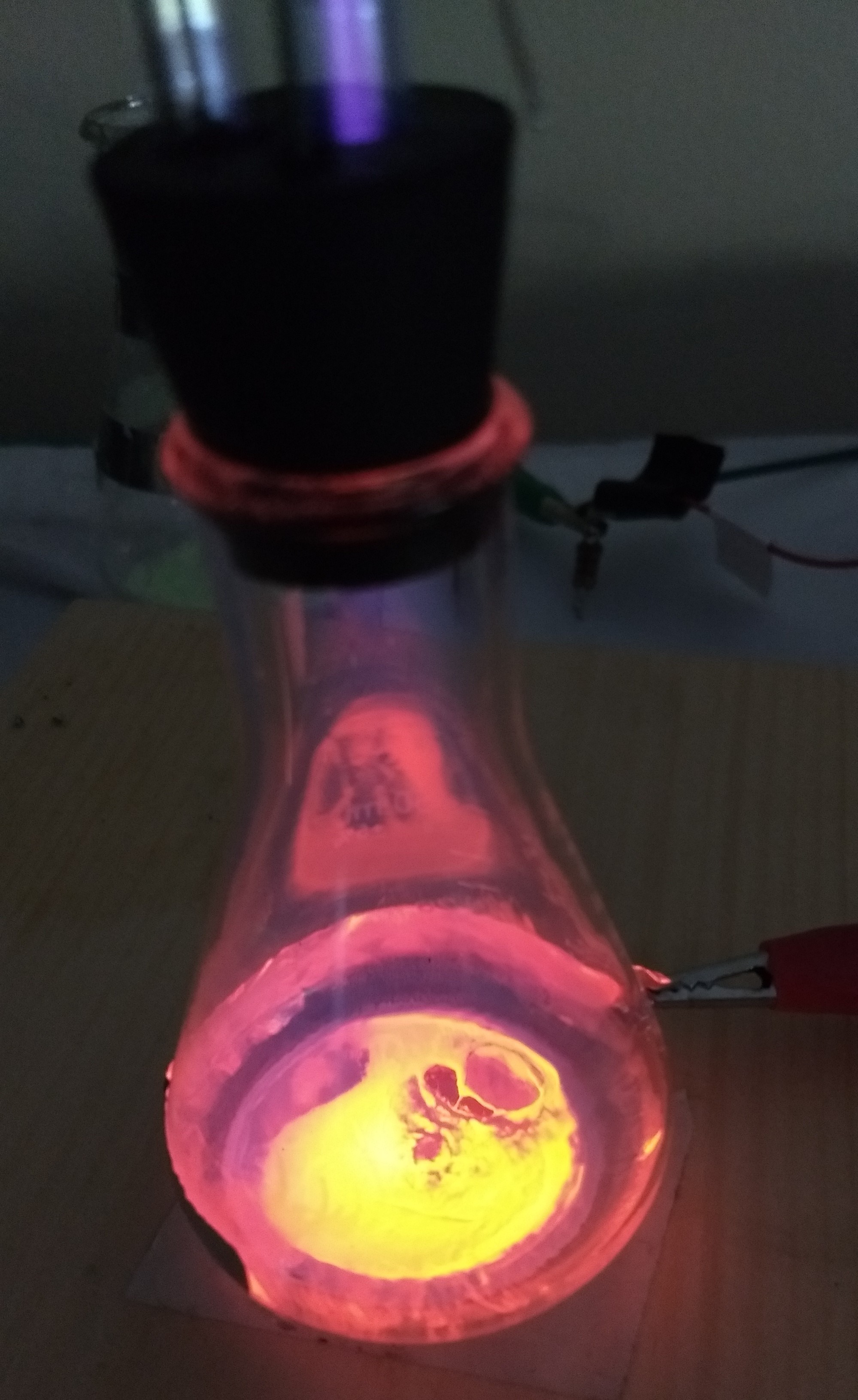
 glowing in the dark powder also called zinc sulfide with copper (ZnS:Cu) glows green A very common and good available mixture is zinc sulfide with copper (ZnS:Cu) or also called glowing in the dark powder. It has a long after glow effect even on light. To build a screen mix zinc sulfide powder with water and a little bit of glue and let it dry on the bottom of the chamber. I recommend glue because without it the screen isn't stable. Otherwise it could happen that the screen blows away by returning air when the vacuum is released.
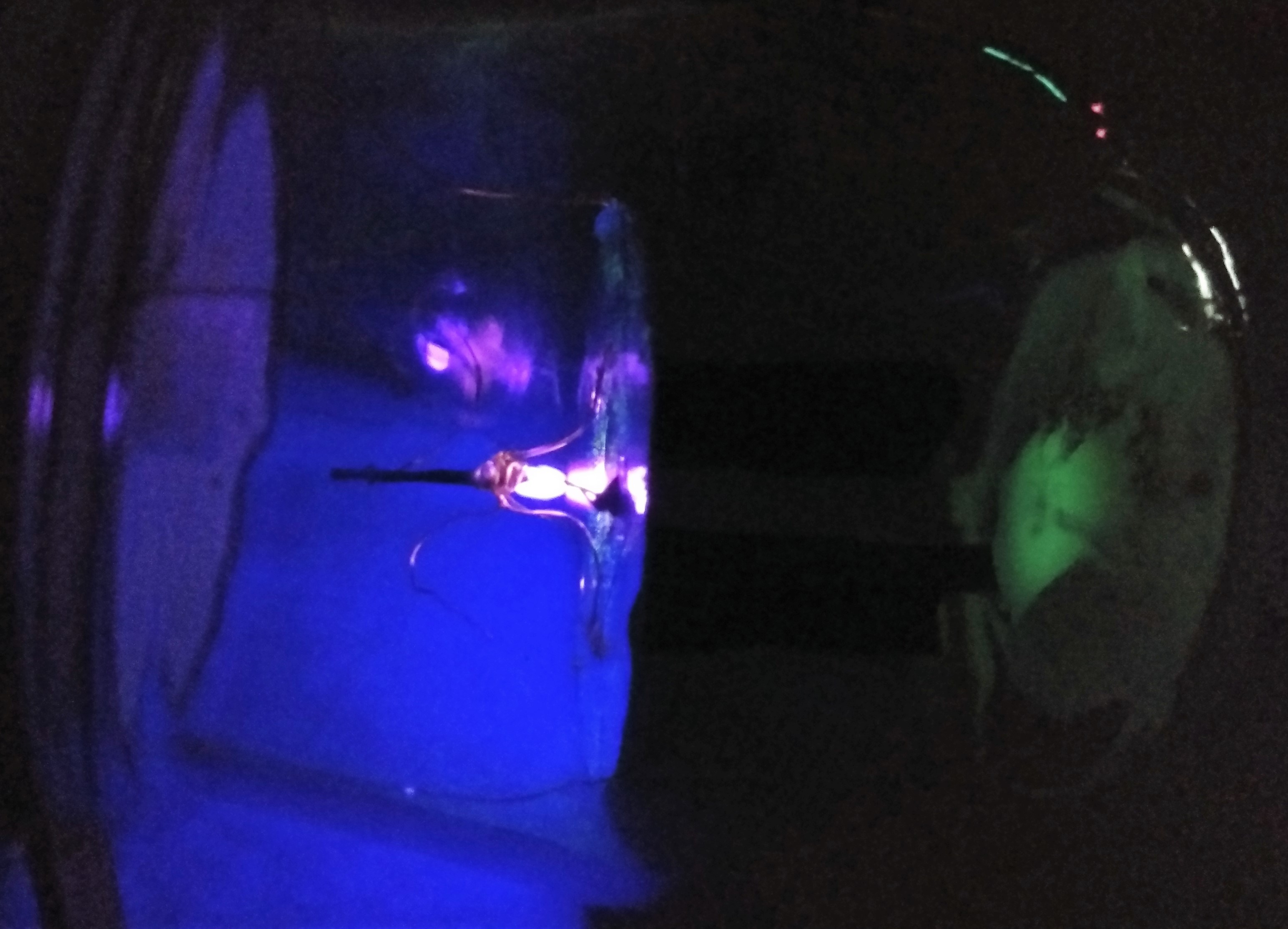 glowing caused by light
 Discharge rings made of aluminum foil
 The image above shows the test setup. The variable resistor RL I realized severl 10Meg Ohm resistors connected parallel.
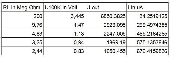
 I got my vacuum pump and started to build the vacuum chamber.
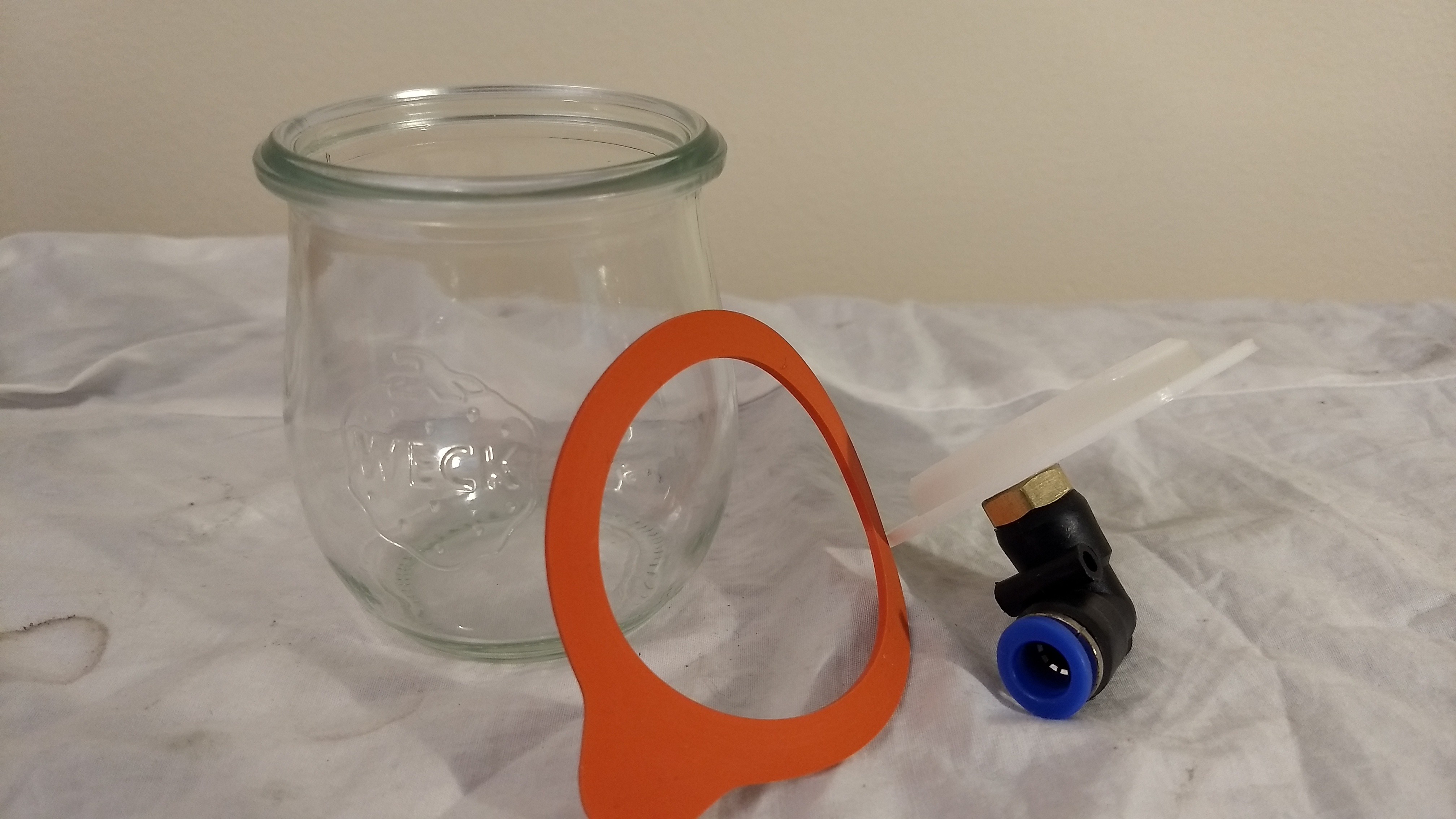

 To get a strong connection between the cap made of PLA and the tube made of LDPE I used a special 2K glue. The special at this glue is, that it is suitable for PE. The most other 2K glues are explicit not recommended for PE or PP gluing.
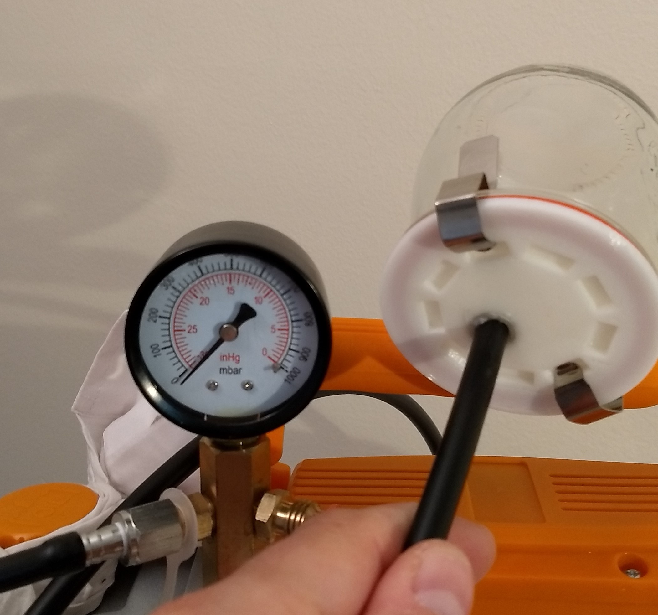
 Today I included the pieces that the electrons interact with the magnetic field and it seems to work. The current version I uploaded on
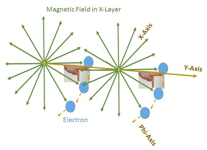
 In one of my previous logs, I explained how I calculate the position (