0%
0%
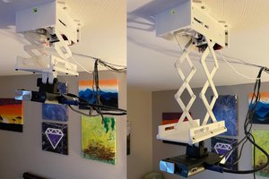
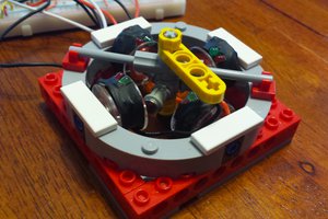
Open Source Micro Cassette Player
It wont look like the elbow elbow cassette player (different)
 Ricardo Ferro
Become a Hackaday.io member
Already have an account? Log in.
Just one more thing
To make the experience fit your profile, pick a username and tell us what interests you.
Pick an awesome username
hackaday.io/
Your profile's URL: hackaday.io/username. Max 25 alphanumeric characters.
Pick a few interests
Projects that share your interests
People that share your interests


 Sam Baker
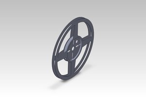
 Adam Smallcomb
 decurus
Interesting concept,
Quick question, how are you going to keep wow and flutter in check with only one spindle.