0%
0%
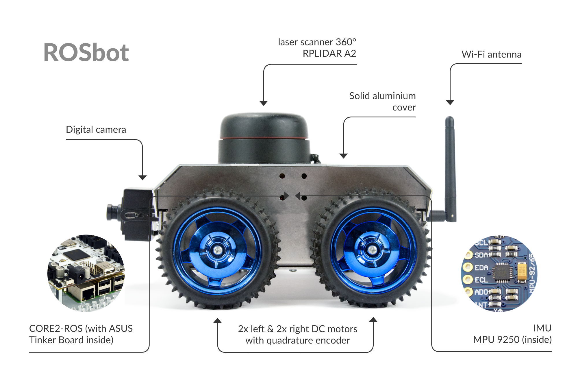
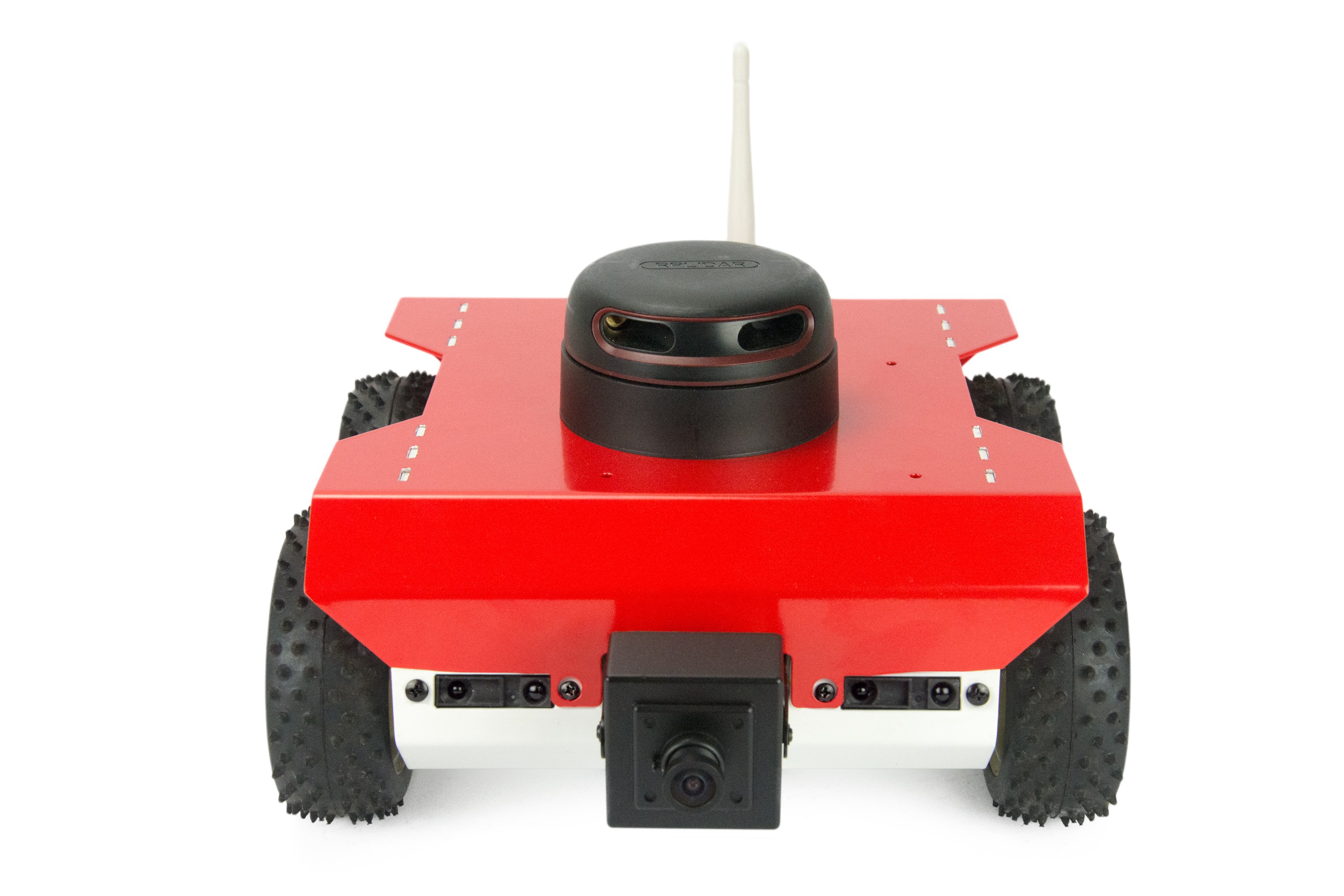
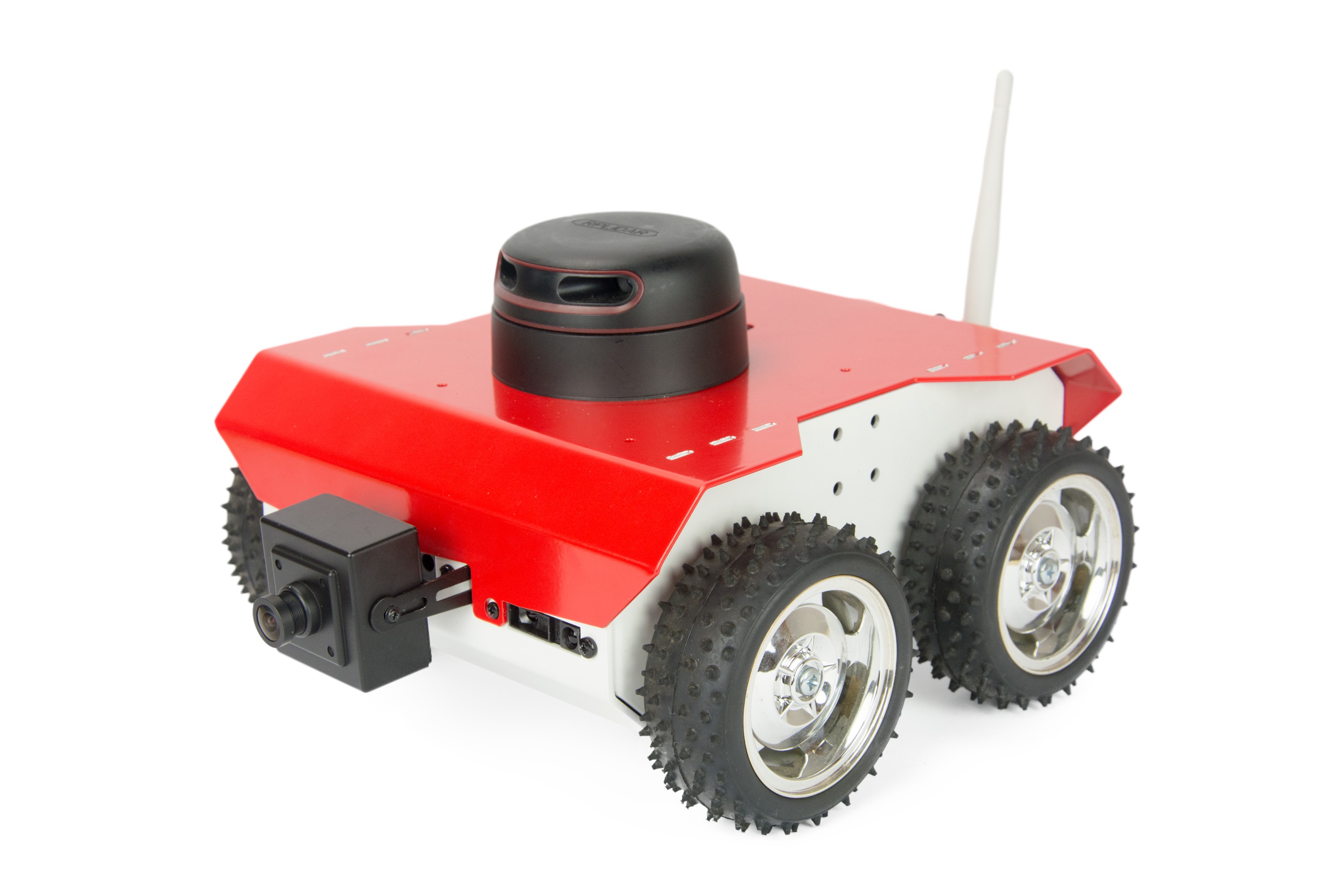
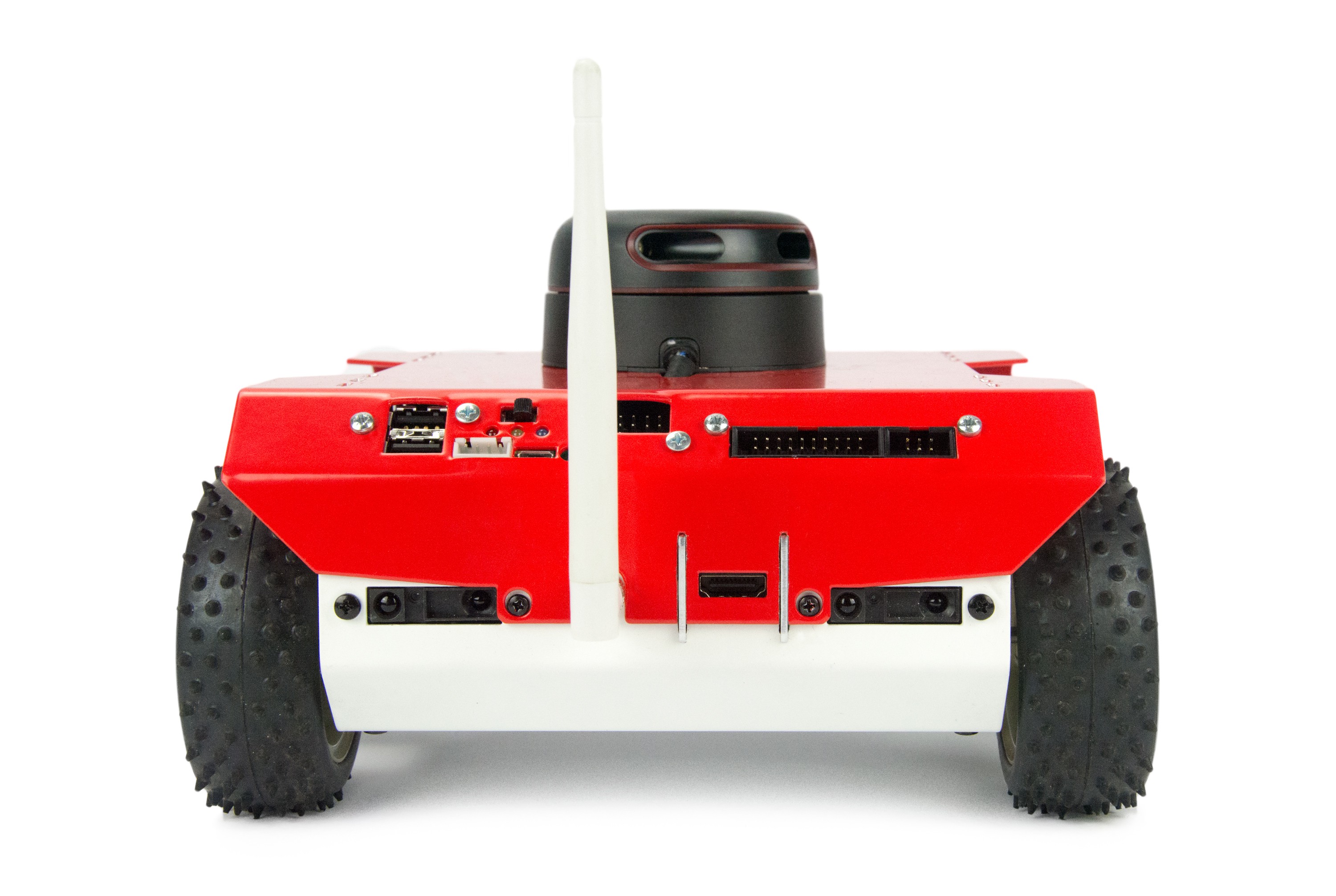
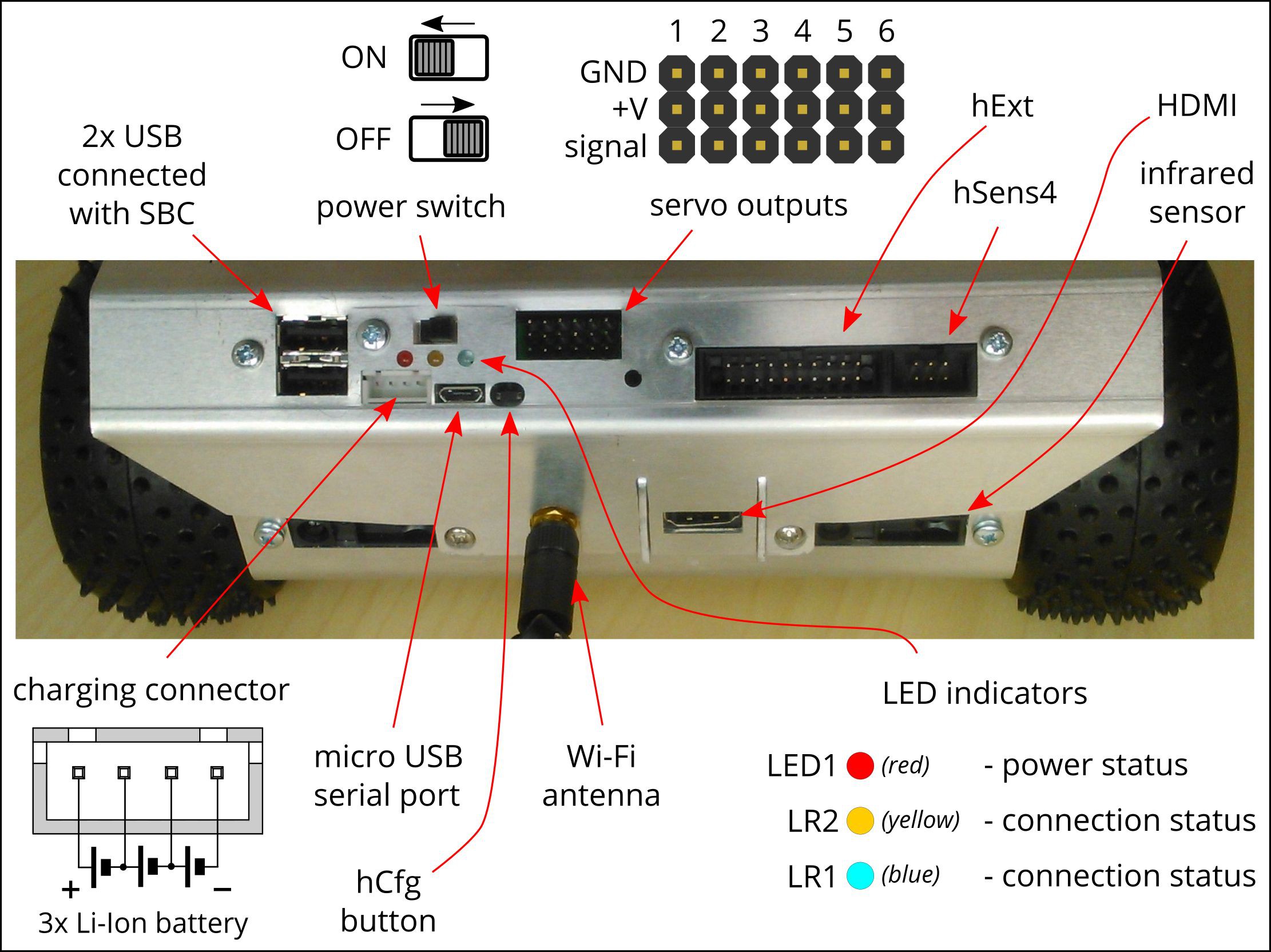
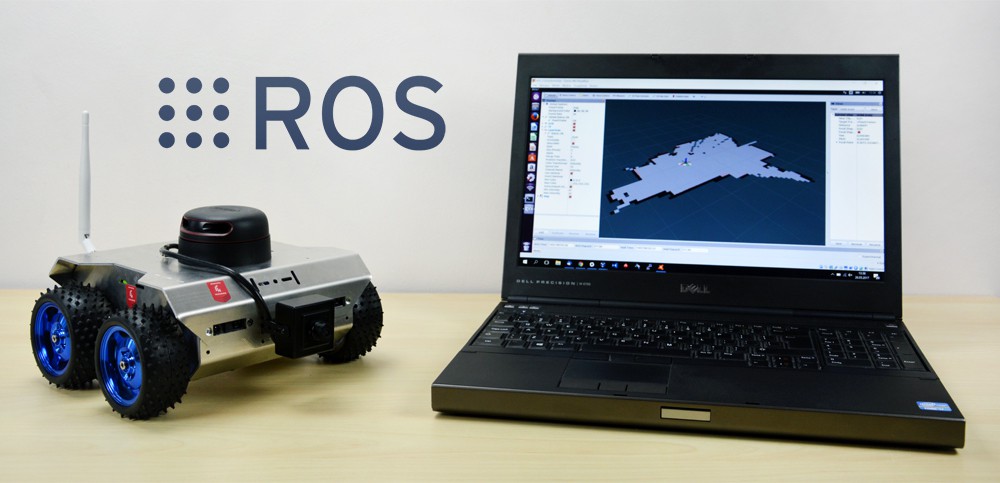
ROSbot - autonomous robot platform
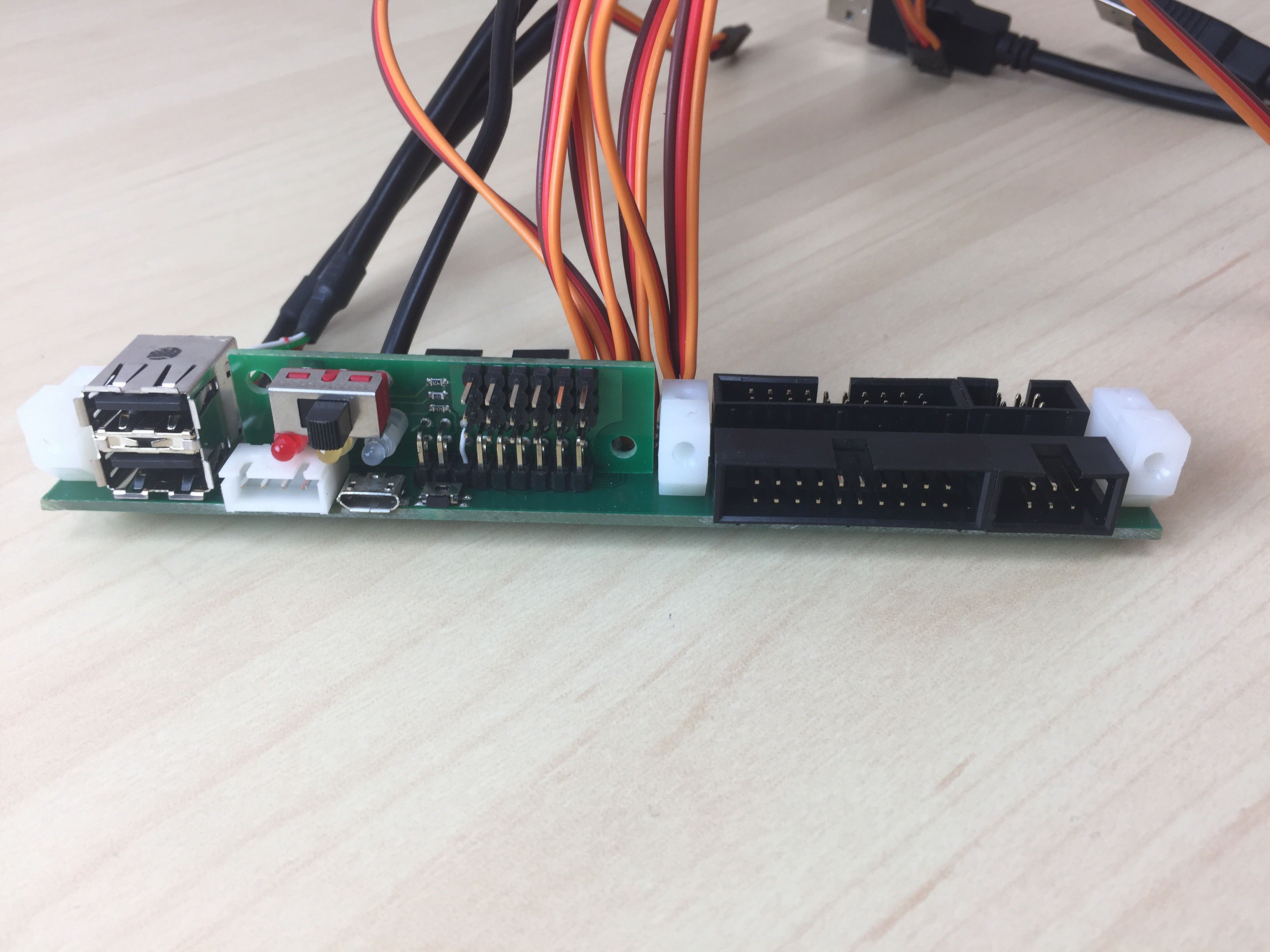
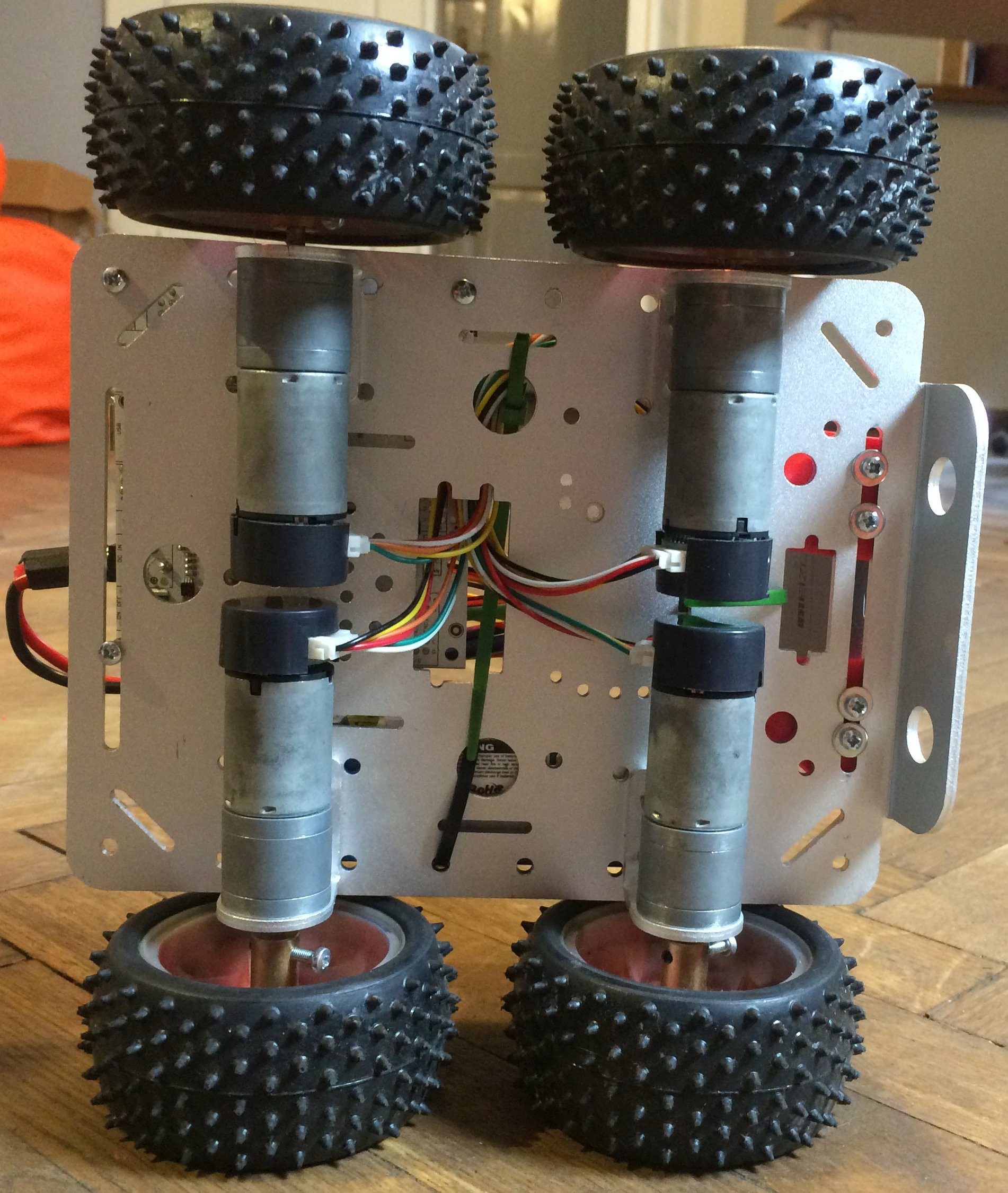
Open source & connected universal robot platform. ROS-powered. Sensors: LIDAR, camera, IMU, encoders, distance sensors. 4 DC motors.
 Husarion
Become a Hackaday.io member
Already have an account? Log in.
Just one more thing
To make the experience fit your profile, pick a username and tell us what interests you.
Pick an awesome username
hackaday.io/
Your profile's URL: hackaday.io/username. Max 25 alphanumeric characters.
Pick a few interests
Projects that share your interests
People that share your interests


I am a beginner. I have to download your project from github, what command to run this robot in terminal?