-
Prism motor new magnets
05/18/2022 at 13:35 • 0 comments- Magnets increased from N52 8x2 to N52 10x5 and the pull force went from 1.1 kg to 3.6 kg.
- Stronger magnets made me realize I had a mistake in my algo, improving the algo also increased torque.- The motor died due to ESD at my workplace. I am still waiting for material so I can properly ground myself
I had to replace the FPGA and the motor chip- motor can reliable self start
- motor requires lower current and voltage (5 volt suffices), heat has become less of an issue. -
Prism spinning using feedback
05/06/2022 at 12:05 • 0 commentsIn short; - I am able to increase the speed of the motor using the hall encoders
- prism speed seems sufficient for exposure
- the motor driver dies over time, unknown why
- I will now focus on the mechanical designIn the figure below, you see the commutation states of a motor.
![]() I have three Hall sensors which detect the position of the magnets. There is a total of 8 states,
I have three Hall sensors which detect the position of the magnets. There is a total of 8 states,
but the state (1,1,1) and the state (0,0,0) are invalid.
Furthermore the states are ordered, so (1, 1, 0) --> (0, 1, 0) is an allowed transition.
But not (1,1, 0) -->(0, 1, 1) as it skips either (0,1,0) or (0,0,1).
If a state is detected then some coils are turned on and off. The coils also only have six states.
The starting point is random now. That's why in the video, I have to kick it in the beginning.
It's a very crude feedback algorithm but able to spin up the prism. I can also read out the frequency which is detected by the FPGA.
A full cycle is 180 degrees, so the resolution by the Hall sensors is 30 degrees.
The prism ends up in exactly the same position after a turn of 180 degrees. This is not dictated by the quartz but the four magnets below it, which have this symmetry.
The main challenge is that the motor driver, the STSPIN230, dies over time. I start with three working bridges but end up with one working bridge. I have no idea why. I limit the current to the chip below 1A and do not go outside the Voltage range.An algorithm can also be designed by simulation of the motor, see article. An old implementation in python is provided by open-blcd. This is quite dated. I looked at GYM electric motor. I think it is able to do the same but could not find the time, right examples to set up something fast.
-
PCB motor rotating a prism with Hall encoder
05/03/2022 at 18:43 • 0 commentsA quick update:
-
Optical weakenss in new design
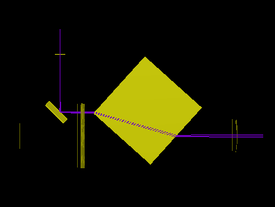
04/03/2022 at 20:03 • 0 commentsIn the new design, I removed the mirror and track the position of the photo diode via a reflection in the prism.
This technique has a weakness.The weakness is as follows, if the center of the rotor is not stable but moves microns during the rotation.
This will propagate to the photo-diode.
To simplify if the rotor translates in the old design nothing happens;In the figure below the prism is moved upward by 10 mm.. Still the photodiode is hit at the same position.
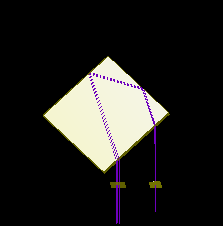
In the figure below the prism is moved 2 mm sidewards
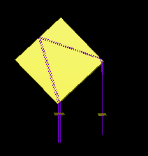
This is very different than the original
This behavior already becomes a problem at say 20 microns. The error is propagated back twofold. The relation seems non linear and become more complex at larger displacement.
The angular position is assumed to be stable due to angular momentum build up. -
Levitron Revolution with EZ Float Technology
03/23/2022 at 21:31 • 0 comments@gravis pointed me to a project which reversed engineered levitron revolution
In the vertical position, the magnet holds like a pound of weight without consuming
any additional power. Video below shows the horizontal position. The device can be tilted 90 degrees!There are people who reached out to me for the current laser head. The current laser head is hard to reproduce while still making a profit. Currently, I will focus on simply producing a cost effective device which is easy to produce.
I admit that a magnetic levitated prism in combination with a laser scanner would be very cool.
I think it should be totally possible to do this with pcb coils.Maybe one day...
Gravis also had a link for customizable magnets;
http://www.polymagnet.com/polymagnets/
A related topic, is levitation of pyrolytic sheets, article has nice video of rotating disk with laser
https://pubs.acs.org/doi/10.1021/ja310365k -
Laser module with PCB motor
03/11/2022 at 11:26 • 1 commentI made a video explaining the design of the new laser module with PCB motor
AMSystems (the company sponsored and powered by the dutch state) released an interesting video. It shows a simulation of the plurality version of the laser prism scanner from 2013. The design was made when I worked there. I think it is made in Siemens NX. Hackaday might like this now they are a Siemens company.
It is a nice render and would be even cooler if it actually worked.. I think they target a price of 60K euro's per module. I hope they also come up with a new working design. -
Update
03/04/2022 at 18:13 • 1 commentA couple of screenshots for those who can't wait;
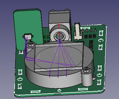
The mirror and cylinder lenses are removed. Five percent of the light is reflected. This is used to trigger the photo-diode.
![]()
For each ray drawn in freecad, the prism is in a different position. I draw them so that I know how to design the system.
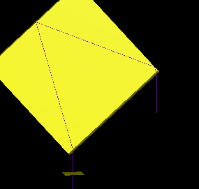
A simulation using pyoptools at 42 degrees is shown below.
A ray goes through an ideal lens is refracted by a tilted prism at 42 degrees. Five percent of the light gets reflected at the second prism facet and is directed to the diode as it hits the third facet at an angle greater than the critical angle (total reflection).
![]()
The prism is not fixed to anything at the moment. I still have to think about this. I envision two solution.
A metal base plane below the pcb using the magnetic force of the magnets or a mechanical push from above.If the prism is assumed "perfect" and somehow sticks to the teflon outer ring, which does not rotate!!, the system is rotational invariant.
A teflon cylinder is glued to the prism, at the bottom four magnets are placed which are 5 mm above the pcb.![]()
Designing the thing will take some more time. An issue, I currently have is that there is too much play between the teflon inner and outer ring. Still, this might be easy to resolve. I might post a video when I send it to the fab.
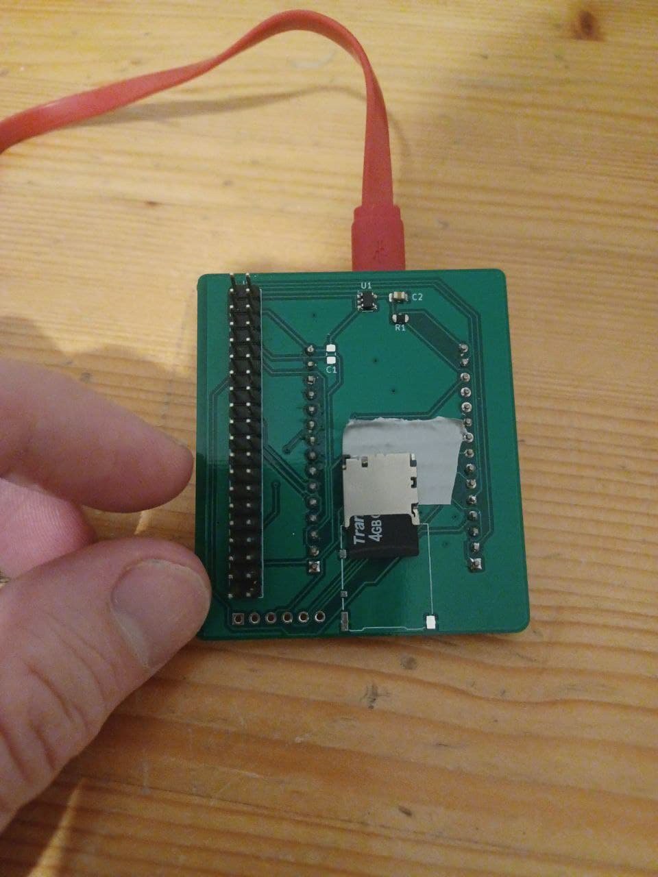
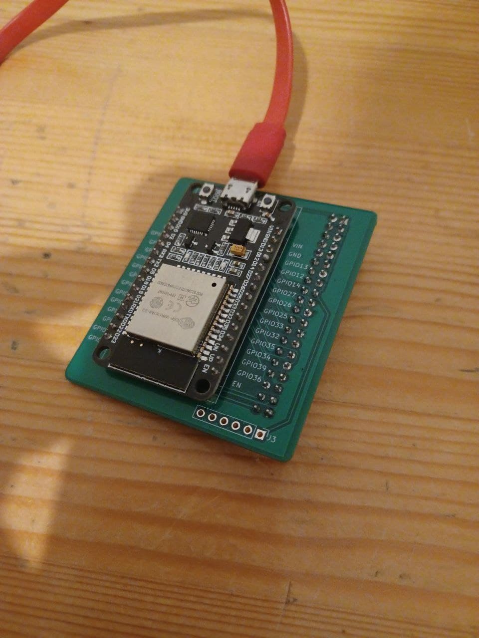
I have also mostly replaced the raspberry pi with an ESP 32 board running micropython.
Most libraries have been ported to the board. Also the libraries which were in C or C++ (fomuflash and TCMStepper). I made a custom board, which can be put in the raspberry pi connector of my main board.![]()
![]()
-
More details on the PCB motor
02/05/2022 at 17:21 • 2 commentsThere is a great write up on PCB motors by Kevin Lynagh with links to patents and videos.
I did some more test with the pcb motor;
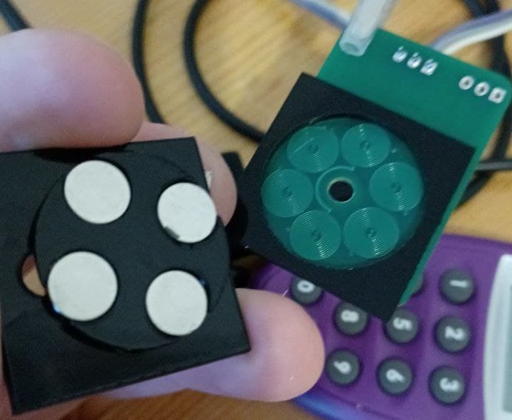
I am now at a speed of 10 Hertz or 600 RPM. The black plastic is acrylic cut with a laser cutter. The metal parts are pieces from a stanley blade. I use an acrylic dummy prism and the metal blade pieces ensure that the magnets are fixated.
An acrylic piece is kept between the magnets so they do not move horizontally. Vertically they are fixed by the attraction of the metal part. Note that the prism does not has a shaft. There is a hole in the board but it is not used. The shaft is the acrylic holder of the magnets. This rotates in the square support. It can be assumed that the prism is perfect, as it is manufactured with a high tolerance. The acrylic is not perfectly planar. Still if the prism rotates it will most likely end up in the same position.The PCB motor is pulsed with FPGA and the typical six step commuation loop. I also switch the field off at the end of a move. This prevents it from being slowed down. I need to optimize this further.
My current plan is to simple reduce the duty cycle if the prism speeds up.
I will also replace the acrylic with Teflon. This will reduce the kinetic friction coefficient from 0.4 to 0.03.
I aim to keep the prism in position by either pushing from above or by placing metal under the board.
Metal under the board to create a downward force is possible, but the whole thing is quite "delicate" and interferes with the other forces and risks that the prism doesn't rotate.The acrylic dummy prism already rotates at 5V and a current of 0.7 Amps. Heat is not a problem if a duty cycle of say 0.7 is used. Temperature is around 50 degrees Celsius.
![]()
-
Spinning prism with PCB motor (bugeja style)
01/31/2022 at 13:05 • 4 commentsmade a pcb motor bugeja style,
Thanks @gravis, for the hint
it took a lot of effort but I can spin prisms with a PCB motor.
The idea is that this enables me to further reduce manufacturing costs, assembly costs
and shrinks the size of my laser head.
The coefficient of static friction is higher than kinetic friction, the prism should be able to go quite fast -
New video!
12/18/2021 at 16:27 • 0 commentsCheck it out!
Followed this Dutch tutorial for making PCB
 Hexastorm
 I have three Hall sensors which detect the position of the magnets. There is a total of 8 states,
 In the figure below the prism is moved 2 mm sidewards
 This is very different than the original
 This behavior already becomes a problem at say 20 microns. The error is propagated back twofold. The relation seems non linear and become more complex at larger displacement.