Mark Mullin
-
Beginning the design of the robot camera mast
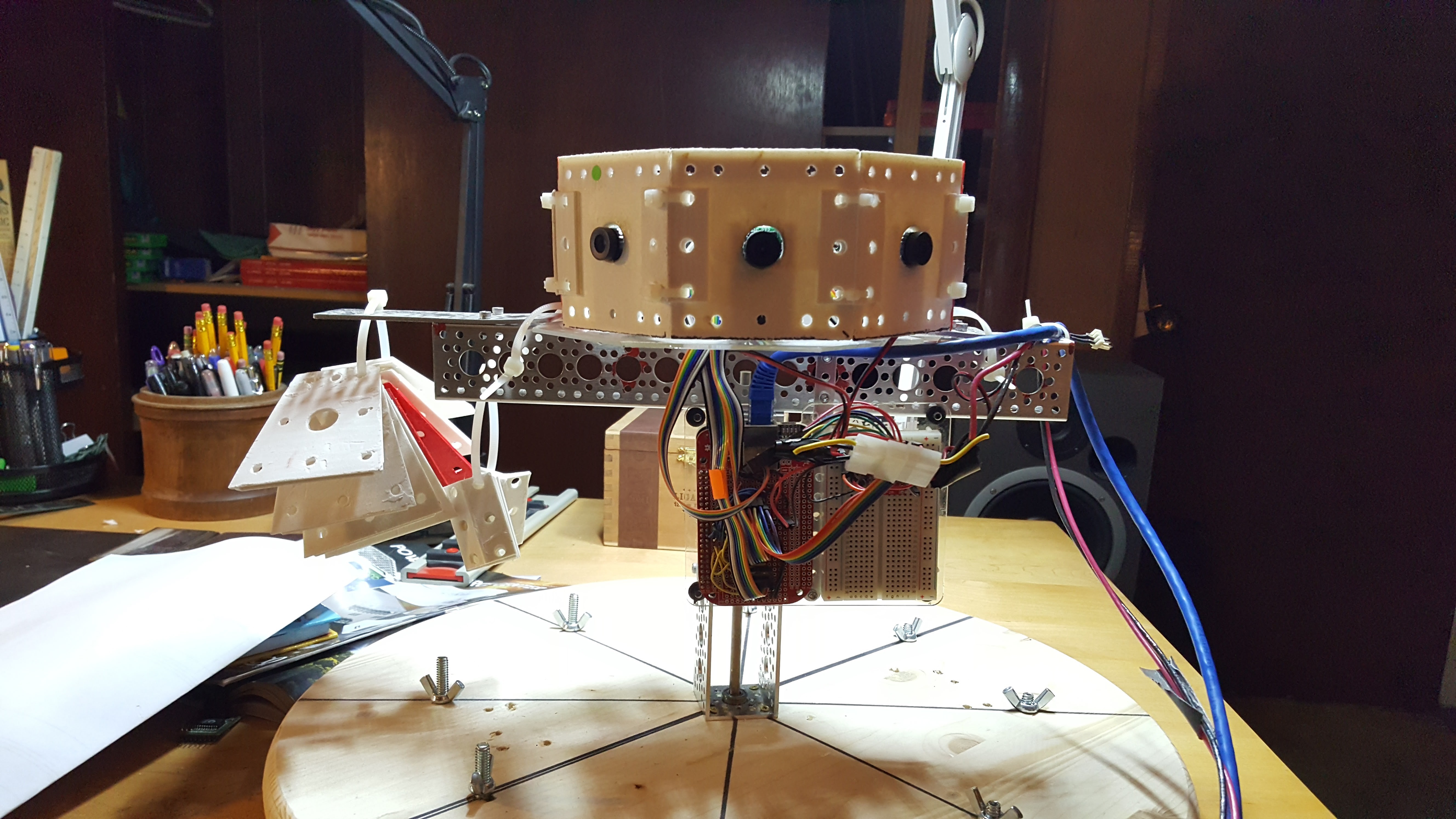
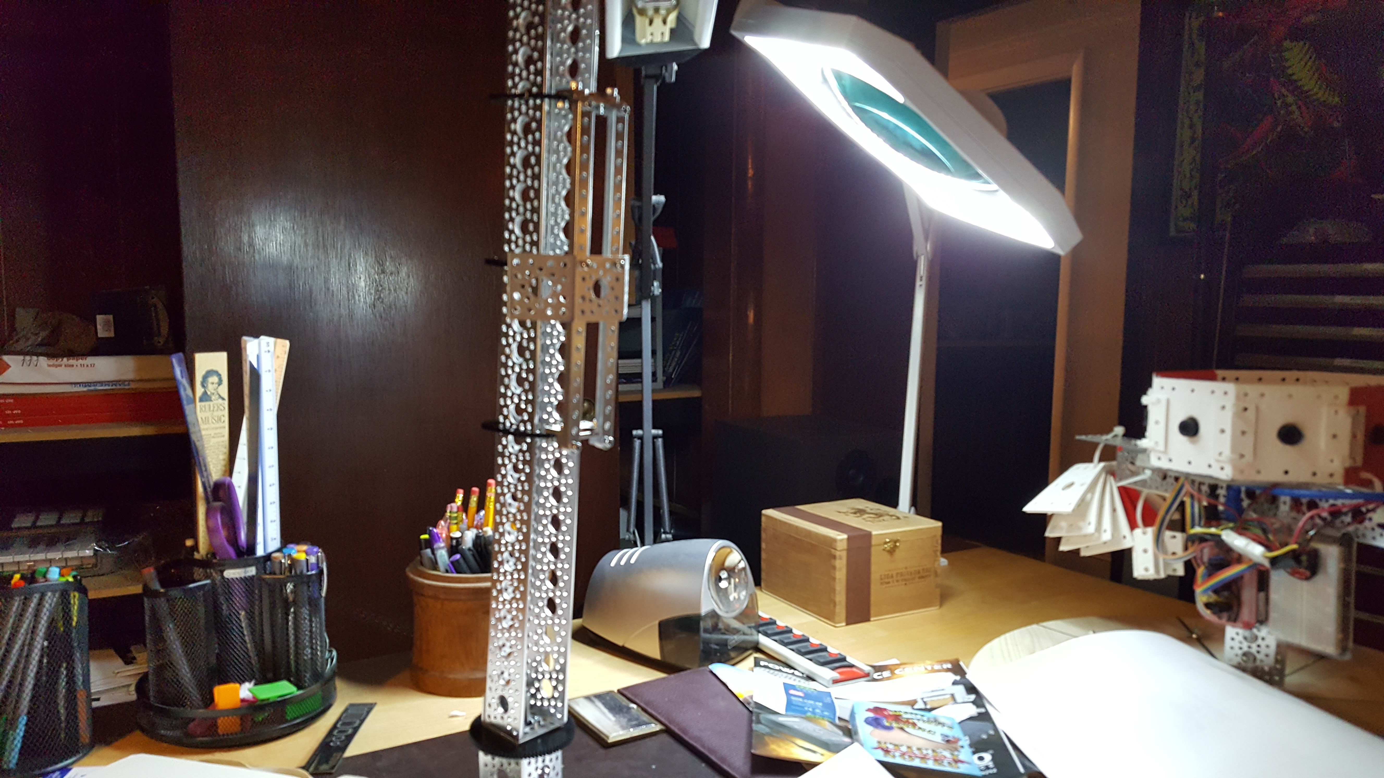
06/06/2017 at 03:31 • 0 commentsIn addition to all of the EE work in bringing up the other two Beaglebones and 16 new cameras, I’ve started designing the robotic platform that will carry the camera. Right now, the single equatorial ring lives on the static platform shown here.
![]()
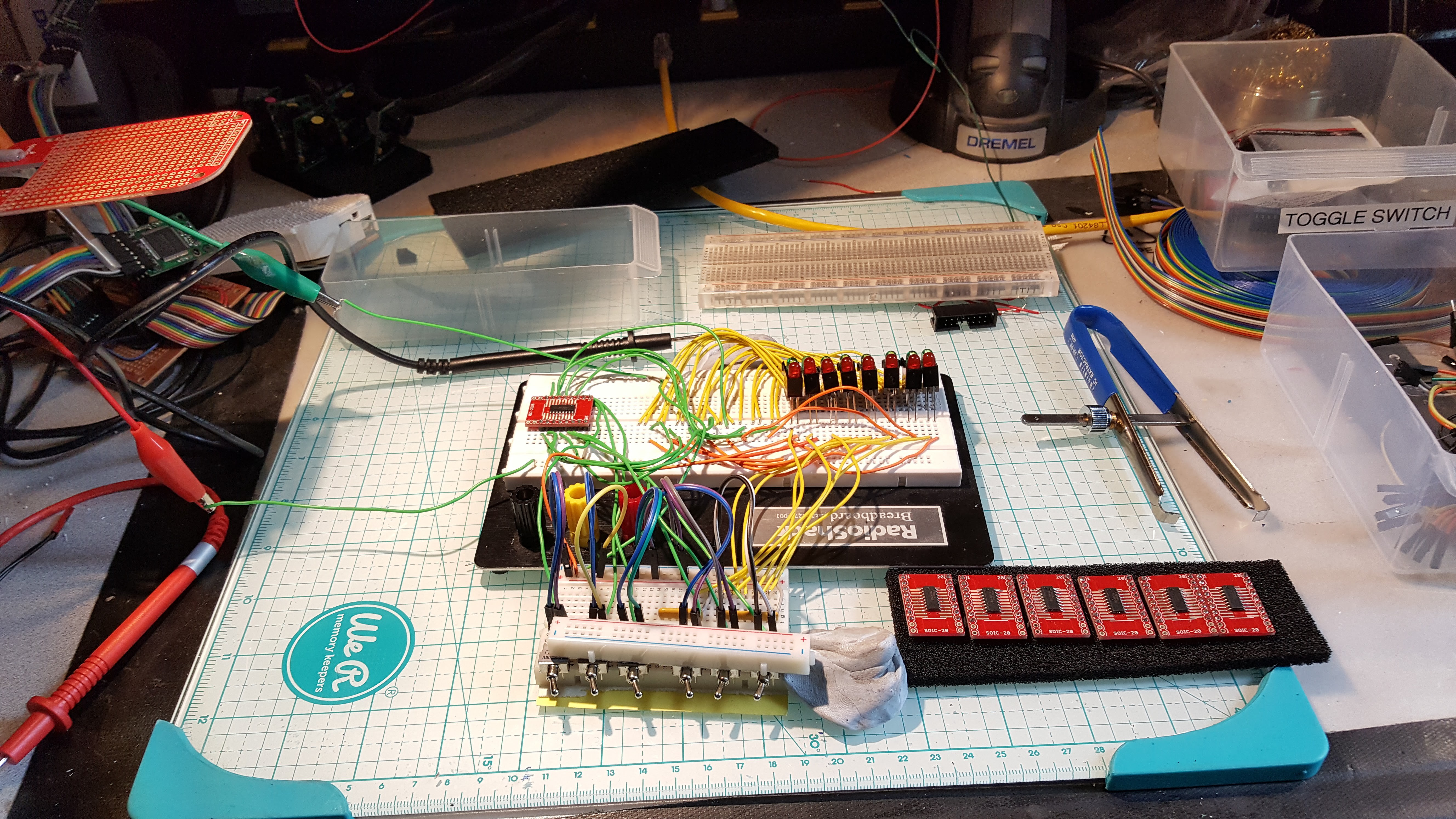
The circuit assembly is a Beaglebone, a custom cape breaking out SPI and I2C for the cameras, and a 74VHC139 in a dip mount in the breadboard
![]()
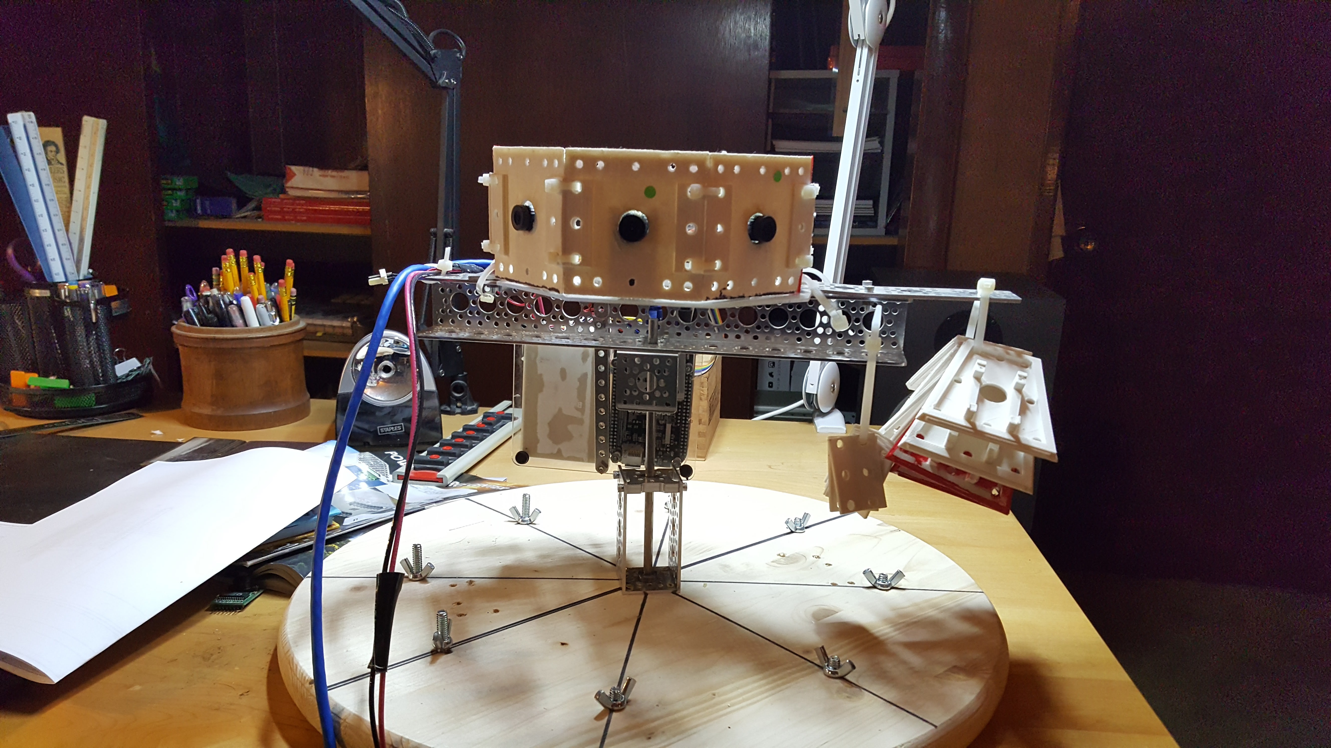
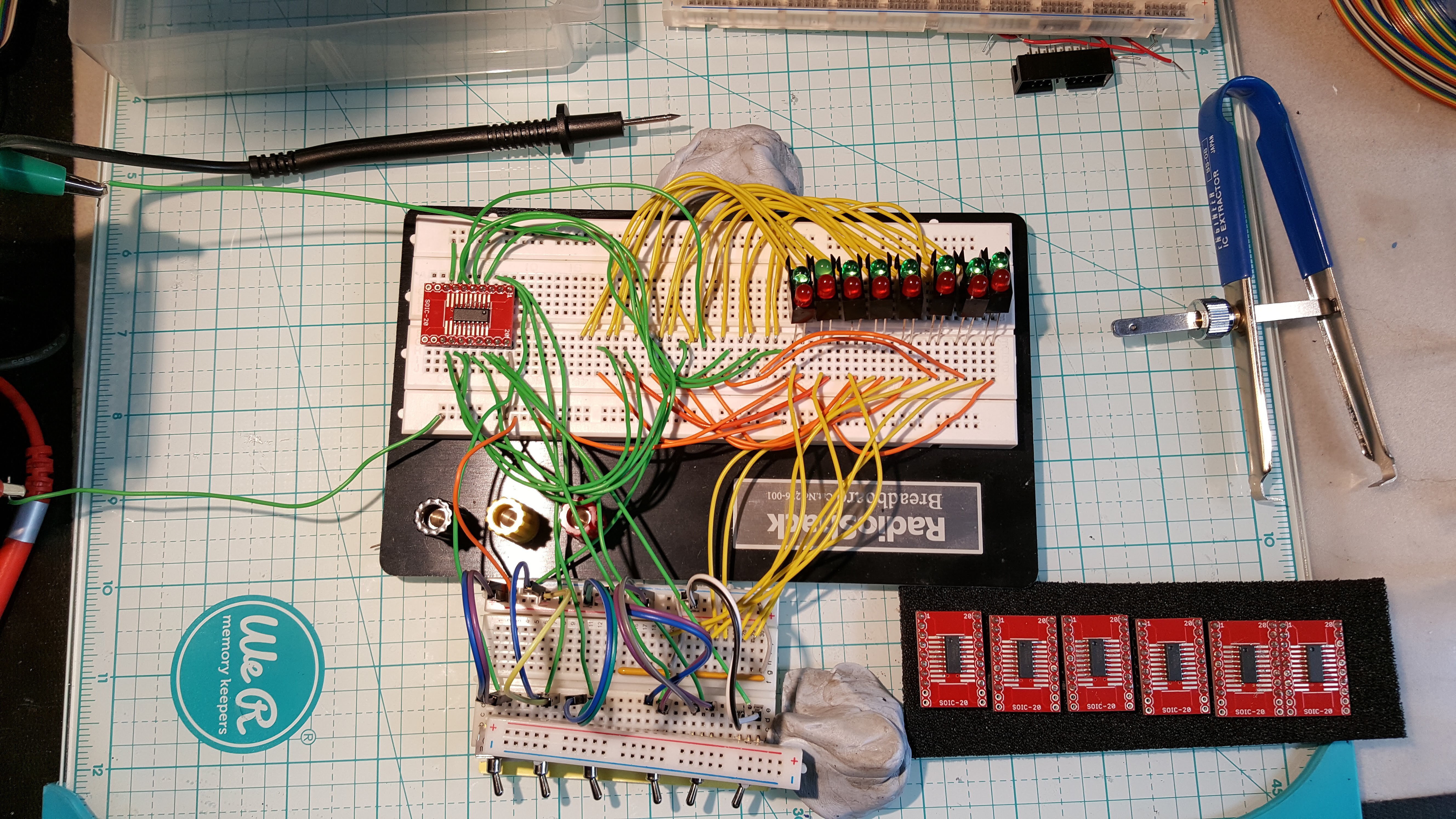
Another view - the stuff zip tied to the right are the angled plates for the upper 45° ring. The lower ring will be the same.
This equatorial ring, along with the upper and lower 45° rings will migrate onto a platform where the computer can move it up and down over a 20” range and can step over a -45° to 45° rotation around the up vector at high speed. The up and down translation adds useful depth information, but the high precision high speed rotation around the vertical axis allows the system to develop a 3D depth map of its environment from a static position, and use the vertical translation to continue to refine the accuracy of the measurement.This is a key part of my hypothesis - can you fuse simply calculated structurally predefined 3D as insects might perceive it with microsaccade scanning to compensate for the weaknesses in our tooling ?
I use Actobotix components for the mechanical assemblies that I don’t print, sourced from www.servocity.com. I must admit one of the reasons for this post is that I’m prepping a document for ServoCity on the Quamera project, since it seems that projects that impress them net a parts discount, and I have a ravenous parts budget. The technical need is to have 20” or so of translation over the vertical axis, to have about 45° of bidirectional rotation around the vertical axis at high speed. This gives the cameras a full RGBD sample set and additional parallax data sets from vertical translation.
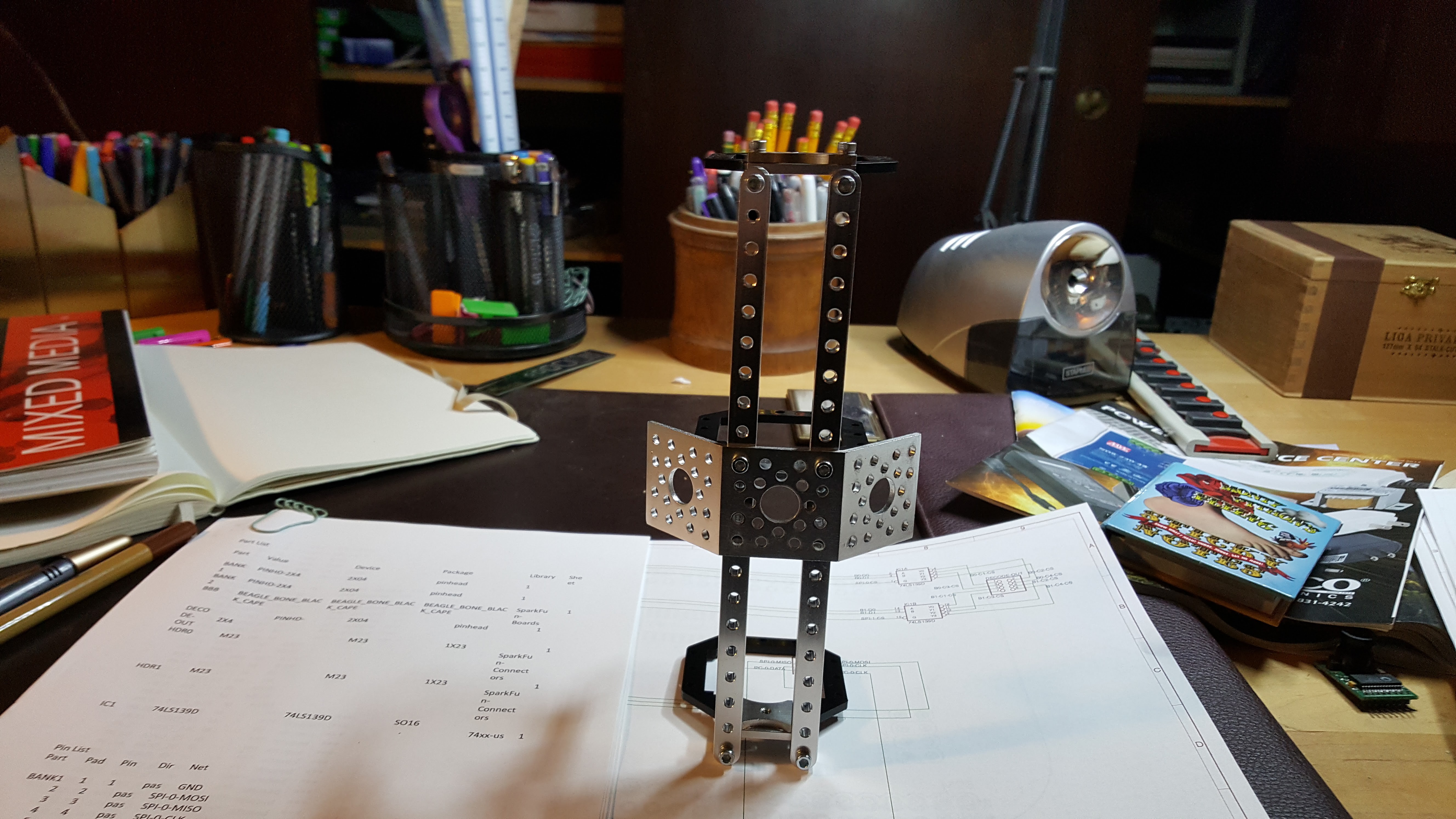
The basic idea is that an armature slides up and down a vertical rail, and all of the camera hardware is attached to this armature – Here are some views of the partially assembled armature, where only one side has the structural rails and one of the 4 mounting surfaces.
![]() Top down view - a fully assembled armature would have 4 of those dual 45° brackets vertically.
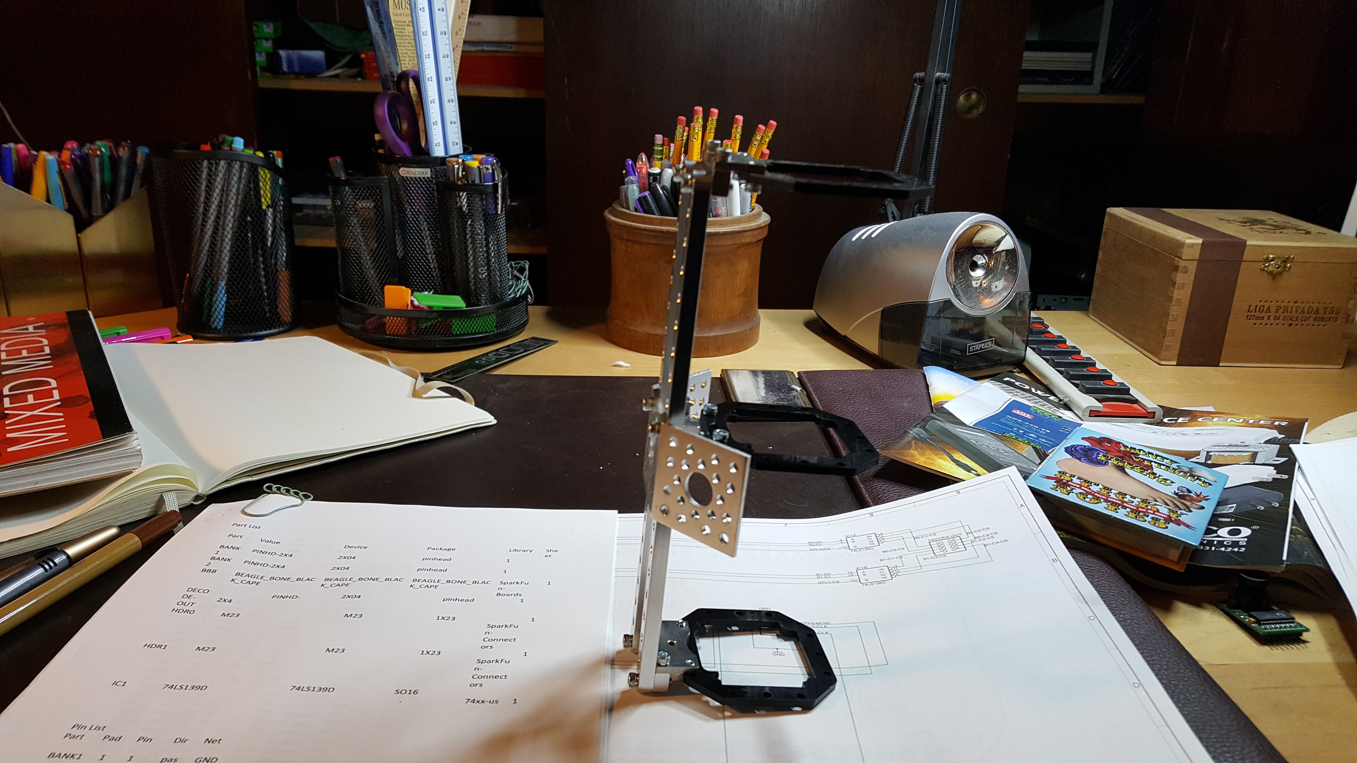
Top down view - a fully assembled armature would have 4 of those dual 45° brackets vertically.![]() side view - the rails in the previous view would be present here as well, however this would not carry any angle brackets.
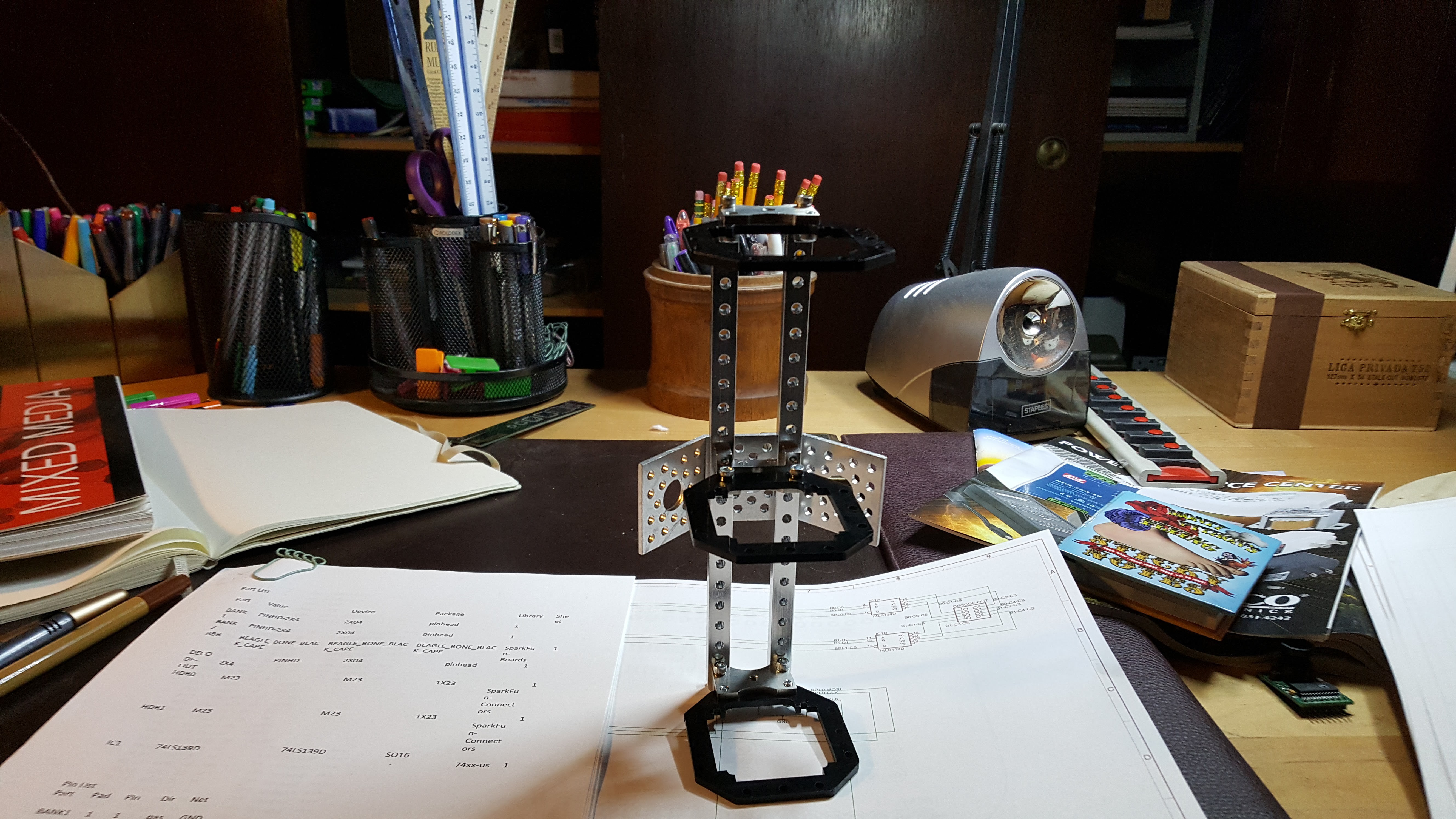
side view - the rails in the previous view would be present here as well, however this would not carry any angle brackets.![]() back view - this would also have the two vertical structural elements like all others and would also carry 4 vertically mounted dual 45° brackets
back view - this would also have the two vertical structural elements like all others and would also carry 4 vertically mounted dual 45° bracketsCompleted, this will be a rather healthy collection of aluminum, riding on 3 Delrin brackets sliding up and down the camera mast. The goal is to have an armature that wiggles as little as possible, as wiggling/backlash/etc can be viewed as a ranged random function and all those do is make my learning algorithms miserable. Doesn’t matter how many dimensions I chase that noise into, if I can't linearly separate it, its sand in my gears. This is a class of problem that seriously frightens me, because it just shows up and says 'Bummer, you rolled a 2 - your maximum certainty is +- 20%.
When it’s completely constructed, the rails you see on one side of the armature will be duplicated on all four sides, and the mounting plates will be running from the top to bottom of the armature at 0° and 180°. All of the 3D printed mounts for cabling and hardware will attach to these plates and a series of struts will connect the external camera plate framework. Part of this is I don't like wiggle. The other part is that I only have one vector to transmit force from my lead screw to the armature, so I need to believe in structural integrity.
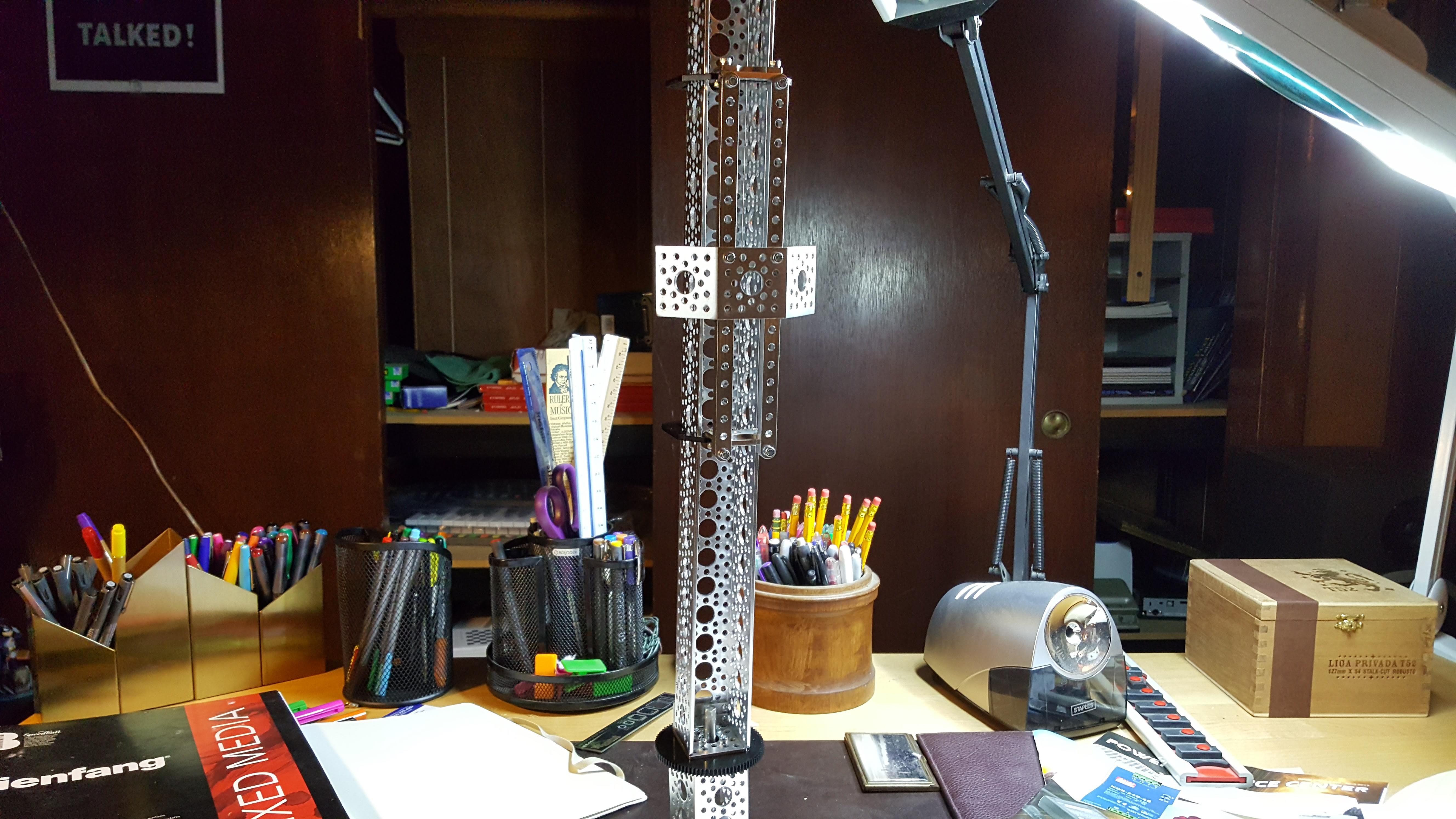
Here are views of the mast with the geared rotation assembly at the bottom and the armature positioned in the middle. The rotation assembly is used to rotate the mast. To rotate the mast at high speed. With an off balance camera armature moving up and down it. This should be interesting.
![]()
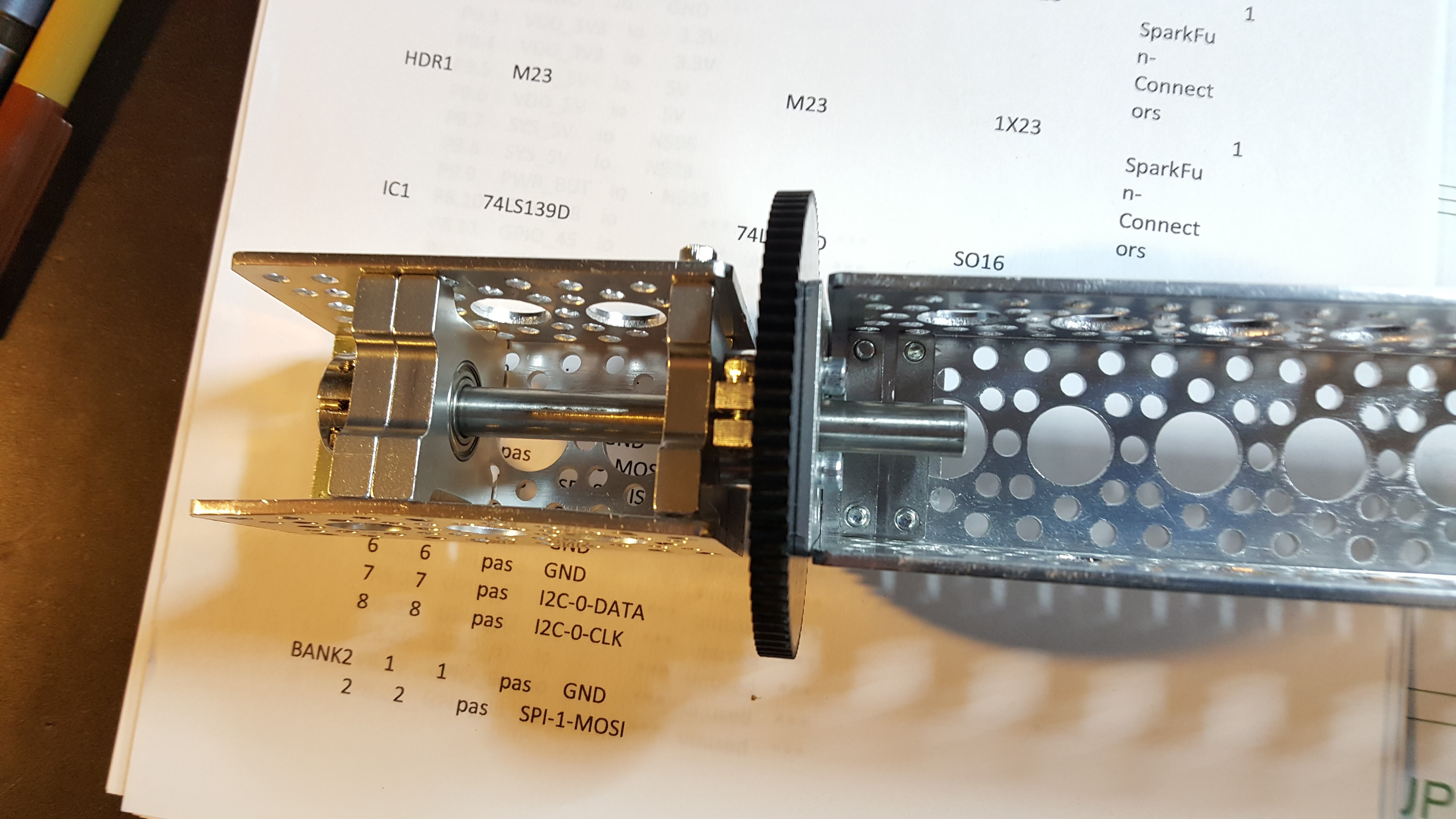
![]() Here's a closer look at the current rotation assembly prototype. Note I'm switching to a design with two equally spaced pillow blocks on either side of the drive gear. I fear the current design just wants to be a lever.
Here's a closer look at the current rotation assembly prototype. Note I'm switching to a design with two equally spaced pillow blocks on either side of the drive gear. I fear the current design just wants to be a lever.![]()
You may ask why this matters. In the short term, because the math is now calling for more data, i.e. the fusion issues on the fixed image sample are best addressed by first providing static upper and lower feature alignment coordinates. Once that’s done, the next best data is gained from rotating the cameras such that the entire visual field has been covered by overlapping visual fields. When motion comes into play, this rotation will have to be quite snappy. Finally, the vertical translation adds additional parallax data, albeit at a grosser resolution, but good enough for a network or several. At this point the system is capable of resolving a static 3D environment in 3D accurately at high resolution.
-
Camera CS decoders done
06/03/2017 at 16:28 • 0 comments![]()
The first precursor assemblies for the full buildout are done. These are sleds that allow me to integrate a SOIC-16 74VHC139 Dual 2/4 decoder with the DIP prototype card for a BeagleBone cape. Of the 8 built, one was lost to solder gremlins in the oven, the other 7 came through the test with flying colors. The pictures show the test jig I whipped up. For simple stuff like this I would rather throw together a test jig with 5V/Gnd switches and LEDS than use the logic analyzer…. Less time wasted trying to figure out if you have the LA configured correctly J The assemblies themselves are visible to the right on small red circuit boards, and one is still in the tester.
I like trying to keep as much of the signaling with the Beaglebones at 3.3V as I possibly can. I have used various level shifters, and I find they can introduce mysteries into the comms signals that I really have no great desire to solve for. The cameras run at 3.3V and the only added complexity is the fact they can’t pull their power from the BeagleBones 3.3V rail, unless I want another magic smoke incident.
Which brings up the next (and last) precursor assembly, the camera interface board. This takes a 16 conductor ribbon cable with camera bus signaling (SPI/I2C) and an 8 conductor cable taking the 8 outputs from the 74VHC139. It also takes an external 5V connection, runs this through a pair of 5>3.3V stepdowns https://www.adafruit.com/product/1065 and feeds this to each camera bank on the 3.3V power rail. The incoming bus signals are split and delivered to two independent 4 camera busses, and the 8 signal lines are directly routed to the chip select line of the associated camera. This provides the 8 individual camera I/O connections. Oh, and the damn thing is noise sensitive. Really nastily noise sensitive. And I don’t want to do a differential. So wiring quality is important L
After that the cables get build, the camera capes to provide endpoints for the 2 ribbon cables and integrate the 74VHC139 are built and mated to the BBB’s and then the built out version goes into lens calibration. It does make for a nice break from all the nasty math.
![]()
-
Prepping for upper and lower angled rings
05/29/2017 at 20:48 • 0 commentsBeginning the work to add the upper and lower 45° rings. I've uploaded the openscad file that defines the plate
-
Public Presentation
05/26/2017 at 13:06 • 0 commentsThe Quamera will be escaping from the lab and going out in public on Saturday August 26 2017 at the Dover Maker Faire. If you're in the New England area drop by, say hi, and meet the beast :-) With any luck the robotic test platform will be done and some more openCV tricks incorporated.
-
Epipolar geometry and more than two cameras
05/23/2017 at 00:07 • 0 commentsleads to numerical instability and poor solutions - oh goody, we're in the land of 'here be dragons' - the insight I'm trying to play now is that if you take all the images and rip them in half and duplicate them, then you can come up with optimal solutions per camera per half - the problem is each half field view is perceived by two cameras and they don't agree (better to say they may violently disagree). However, it is an affine transform at the end, and I know that the image breaks are perfect, i.e. if I map the transforms they should refuse - the question is can I drop the depth information out that way.........stay tuned..... wish me luck if you would.
-
Final baseline data
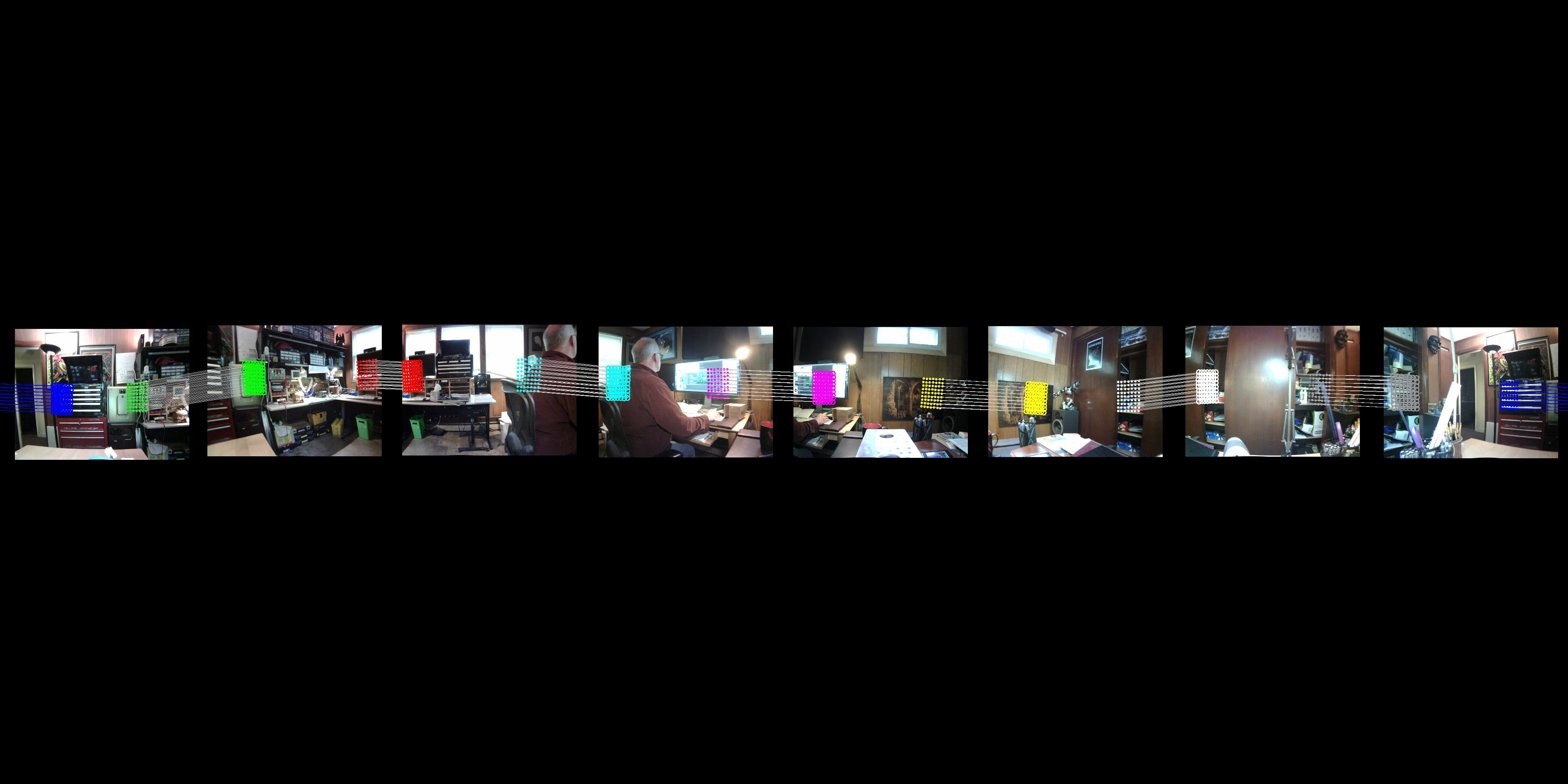
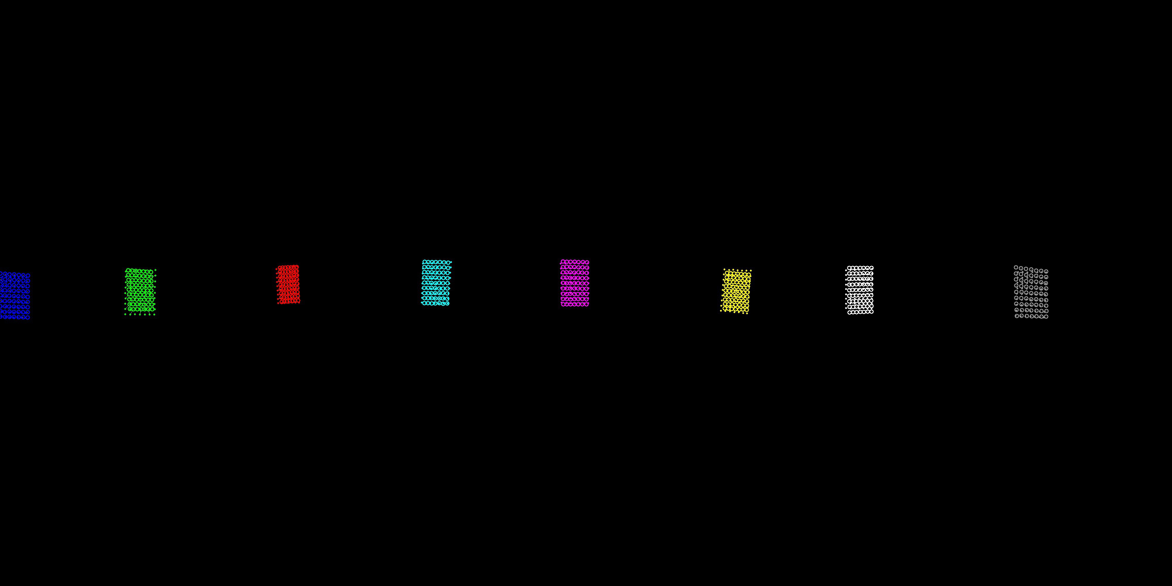
05/16/2017 at 23:48 • 0 commentsHere's the end of the baseline status - first, here's a nice picture that shows how the system has fused a series of checkerboard patterns it saw and calculated the field of view and attitude of all lenses (yeah, I punted on lens translation for the nonce) The solid dots represent the coordinates as seen in the right field of view of the counterclockwise camera and the hollow circles the location of the same coordinate as seen by the clockwise camera in the left field of view. A white line connects the two. The goal is to get the dots inside the circles. The enemy is noise. Lord of the Rings orc horde level amounts of noise :-)
![]()
But, not too shabby - calibration patterns are 68.5 cm away from the camera, local undistortion has been done, and it's not like stuff is scattered to the four winds.
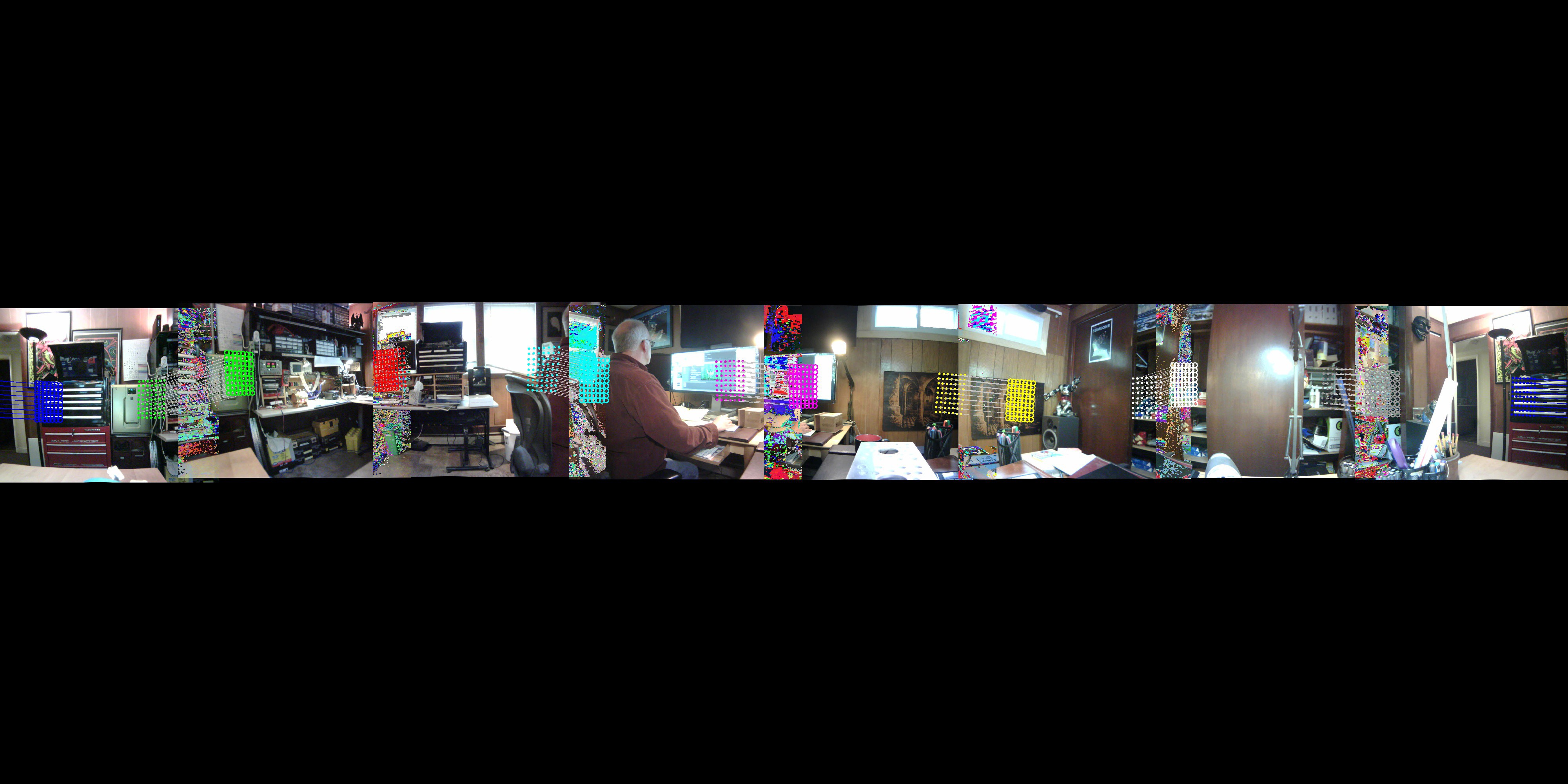
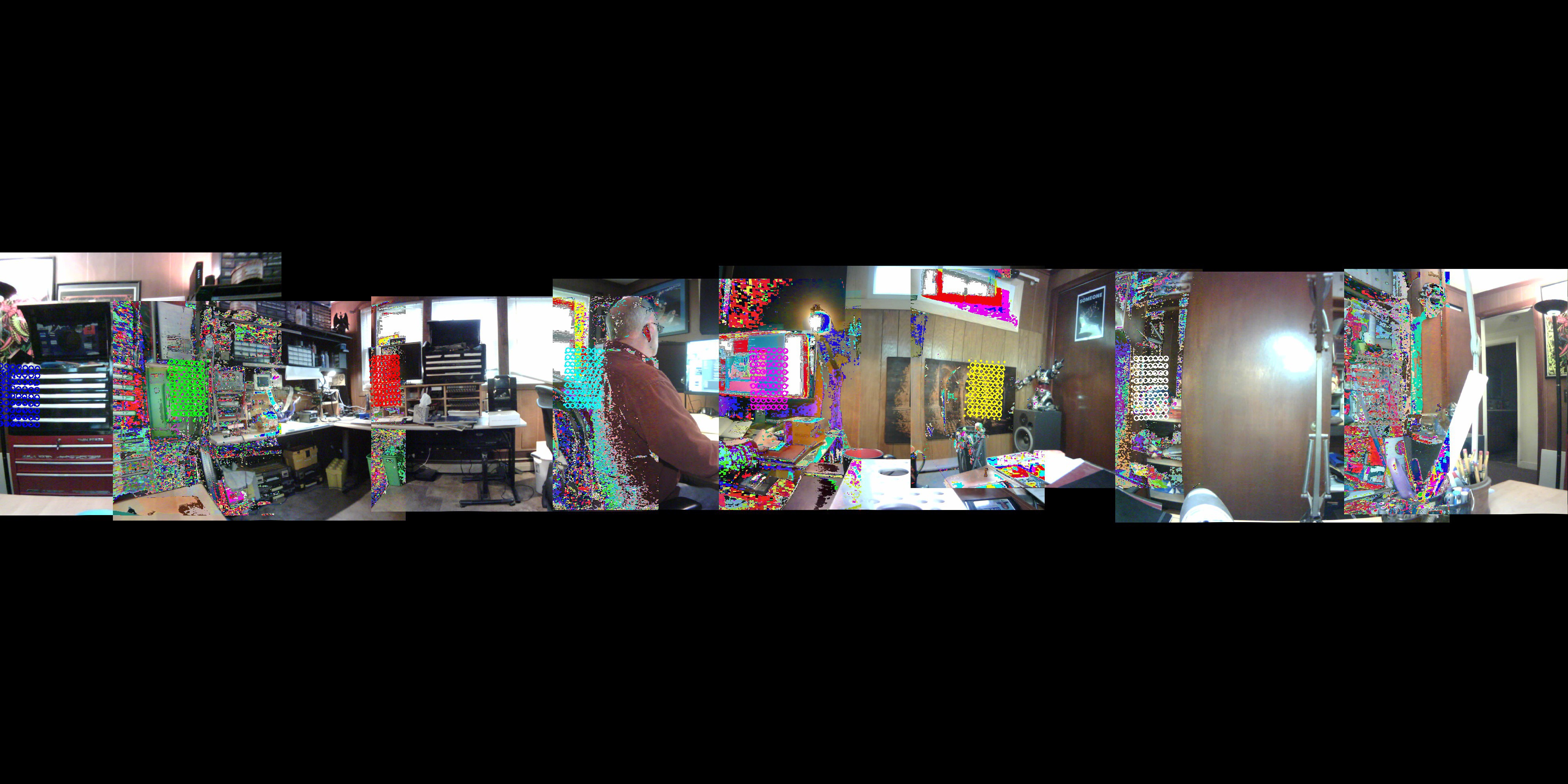
Welcome to machine learning, or, lets solve our problems with a lot of stats and incremental error reduction. The problem is that reality gleefully rolls around in the mud of non-linear systems dynamics, and........ if I put the actual images in place, here's what bozo came up with.
![]() In parts it's done quite nicely, in parts it seems deranged, however what is clearest is that everything changes everywhere and you really can't trust a damn thing until it gets to be a habit. Now, there's obviously a need to rectify all of the undistorted images, which is going to be a trick since it's a fully circular field of view. However, this won't finish here - two tensorflow systems have to be integrated now, one to control voting on FOV/Attitude adjustments, and a much larger nastier one that handles non linear distortion of the image onto a hypersphere. We have to use a hypersphere for two reasons. First, we have no idea how large the actual space is, but we need to be able to quantify it externally. Space grows as long as a quamera delivers data for it, but a quamera needs space to deliver the data to. Secondly, and more interestingly, note that while two cameras having overlapping fields of view may align with respect to intersection of rays on a common visual sphere, they actually do have completely different opinions about the angle of incidence, which arises from their separate locations in space. In simple terms, the answer to 'what value lies here' is a function of your point of view.
In parts it's done quite nicely, in parts it seems deranged, however what is clearest is that everything changes everywhere and you really can't trust a damn thing until it gets to be a habit. Now, there's obviously a need to rectify all of the undistorted images, which is going to be a trick since it's a fully circular field of view. However, this won't finish here - two tensorflow systems have to be integrated now, one to control voting on FOV/Attitude adjustments, and a much larger nastier one that handles non linear distortion of the image onto a hypersphere. We have to use a hypersphere for two reasons. First, we have no idea how large the actual space is, but we need to be able to quantify it externally. Space grows as long as a quamera delivers data for it, but a quamera needs space to deliver the data to. Secondly, and more interestingly, note that while two cameras having overlapping fields of view may align with respect to intersection of rays on a common visual sphere, they actually do have completely different opinions about the angle of incidence, which arises from their separate locations in space. In simple terms, the answer to 'what value lies here' is a function of your point of view.Cleverly placing the td/dr at the end, the pictures show what's being done right now repeatedly in near real time, and there will now be and intermission while I get a whip and a chair and go play with TensorFlow
-
Baseline and rational fusion limit
05/16/2017 at 00:52 • 1 comment![]()
This is what the system knows when it's started cold and doesn't have any knowledge of the exact camera configuration. You can see the horizontal field of view is way to small in the baseline image, however you can also easily distinguish the individual camera images which are to be fused
![]()
In the second image you are seeing the optimal non-stocastic solution, i.e. the system has reduced the error as much as it can without bulldozing the error about in the process of making it smaller. In other words, this is as close as you can get with simple math and an insistence on easily reproducible results. After this it becomes a much nastier problem.
Interestingly enough, check the red grid - we've got a provable, easily repeatable major error reduction on this grid, while the others are to one degree or another problematic. It's one of the things I love about this class of problems - ' <bleep> your NP hard, cause I'm an albatroz - there's no optimal solution at all. You pays your money you takes your chances' :-)
Next I'll post some images from the stochastic solver, which is pretty good at driving the grids to near closure. It's only problem is that I have a sneaking suspicion it's crazier than I am.
For those with idle time on their hands, the attached JPEGS hopefully have kept their EXIF data which defines all the camera angles and FOV's, descriptions, etc - would appreciate any input from people with advice on how to explain to EXIF that, umm, there's a whole mess of cameras that made this image
-
Plan File
05/12/2017 at 19:19 • 0 comments* Planning for camera upgrade to Arducams coming camera - global shutter, 30 fps @ 1280x1024, electronically controlled optical zoom lens
* Work on hyperbolic sphere geometry math (non Euclidian space) that allows the system to perform final overlap while still preserving separate incidence angles
* Move python proto for linear fusion off of mac and onto Jetson, using C++ and Cuda goodness
* Design the 45 degree angle plates and the polar plates
Quamera Gen 2
Stereoscopic machine vision with integrated depth information
 In parts it's done quite nicely, in parts it seems deranged, however what is clearest is that everything changes everywhere and you really can't trust a damn thing until it gets to be a habit. Now, there's obviously a need to rectify all of the undistorted images, which is going to be a trick since it's a fully circular field of view. However, this won't finish here - two tensorflow systems have to be integrated now, one to control voting on FOV/Attitude adjustments, and a much larger nastier one that handles non linear distortion of the image onto a hypersphere. We have to use a hypersphere for two reasons. First, we have no idea how large the actual space is, but we need to be able to quantify it externally. Space grows as long as a quamera delivers data for it, but a quamera needs space to deliver the data to. Secondly, and more interestingly, note that while two cameras having overlapping fields of view may align with respect to intersection of rays on a common visual sphere, they actually do have completely different opinions about the angle of incidence, which arises from their separate locations in space. In simple terms, the answer to 'what value lies here' is a function of your point of view.