To make the experience fit your profile, pick a username and tell us what interests you.
We found and based on your interests.
No updates on hackaday but still lot of progress going on.
Now testing ODrive as motor controller. First tests look very promising but some issues still need to be worked out.
There are also some major upgrades on mechanics tool as you can see on image.
Some testing done with automatic toolhead changing.
CNC machines and we are running long days to get parts available for others too.
Some more images and clips Instagram too @innonium.
There have been lot of activity in workshop in last months. Many new cnc machines arrived and those took it's own time to got setup. Now those are making effectively parts for brdMaker too. if interested what happens in workshop follow my IG account @innonium.
Lot of work is done around feeder backplane. Feeders are now connected with I2C bus. Backplane defines slot based address for every feeder. All feaders can also be upgraded over I2C bus.
One of the biggest change in the machine is the possibility to use brdMaker also as a precise stencil printer.
Printing is yet manual but there are plans to make that automatic too.
Just few improvements to mention from last weeks. Here few shots from the shop..
Lot of development has happened around brdMaker. One of the biggest changes has happened around the mechanics. On new mechanics all axes run on double rails to improve accuracy even more.
Biggest change has happened on the toolhead. Whole toolhead is designed for quick replace. brdMaker can even replace toolhead on the fly.
Pick and place toolhead is optimised for size and made compatible with quick connection.
There is some initial development going on with paste&glue dispensing toolhead to name a one...
Own magnetic nozzleholder is designed to enable automatic nozzle changing with very low runout.
Feeders are organised into racks having backbones. Lot of software development done on the feeder management system.
Custom bottom light system works nice.
Here some activity shots from our instagram account @innonium.
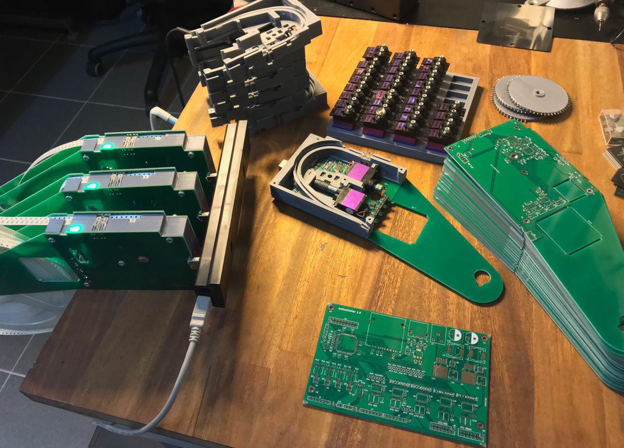
Sorry about the silence. I have been very busy starting new company - innonium.com
There is lot of progress with the brdMaker.
On feeders, there is second revision going on feeder controller. In picture there are some rev.1 feeders plugged into usb hub. in general works guite nicely. Gang mode(all feeders visible under one serial port) still needs some work. Now working with the feeder rack mechanics, so that feeders can be easily hot plugged into machine.
in front there is own "smoothie compatible" controller pcb for the brdmaker. Own controller can be customized better for the needs of the pnp.
On mechanic side there are huge changes. There is new design for the pnp head that enables automatic juki nozzle changing. Also other mechanic is under heavy redesign to optimize accuracy and work area.
Thanks for following!
Controller now integrated inside feeder. Can be used/flashed over usb serial. Also contains rs485 for connecting multiple feeders into same bus(spring pins not visible). 2 motor drivers, 4 buttons and 1 rgb led on top.
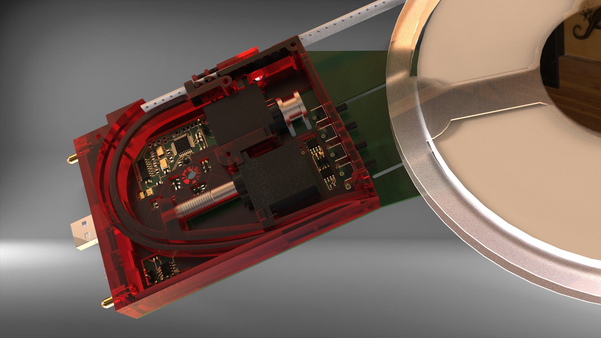
There is very good support for vacuum sensing in OpenPnp. I finally managed to draw board for the sensor. Sensor(MPS20N0040D-D) sticks directly into vacuum channel. There is op-amp on board as well as 2 HALS for Z height sensing. Going to use SmoothieBoard temperature inputs for the vacuum sensor input.
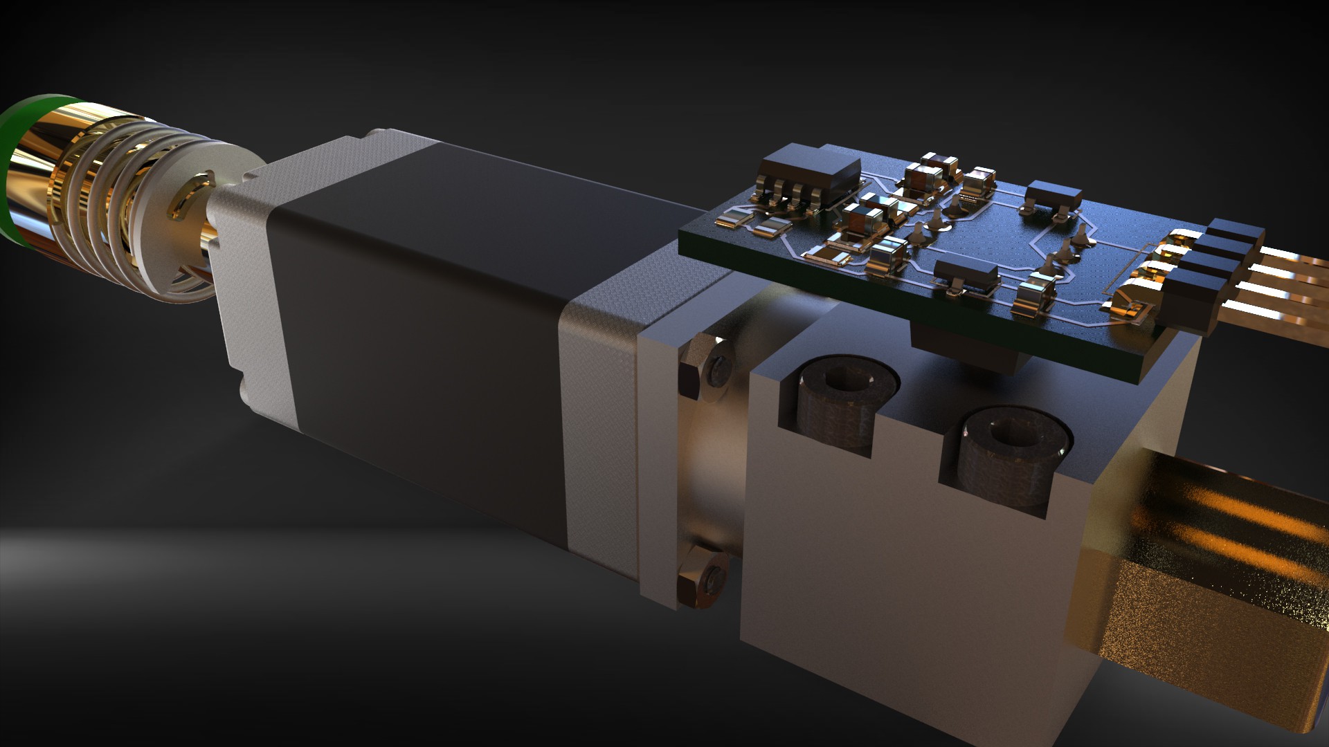
Hal sensors arrived from TI. They have great sample service provided by Digikey.
I ordered drv5053's that are very basic linear output Hal sensors. After trying different location for detection i ended up to place sensors under the gear driven by the worm gear. After multiple trials i ended up to place 4 of those between every 90 degrees. Magnet was "stick" shape moving on radius between the sensors. Problem was that neodymium magnet was definitely too strong, it was saturating the HAL sensor when getting close. Also setup was very sensitive to many environmental changes. I decided to change setup so that magnet would be less powerful and circular shape having poles on round sides. Also sensors would work in differential mode, 2 sensors in x axle and 2 in y axle. Position angle would be calculated from x,y vectors. Lets continue when magnets arrive.
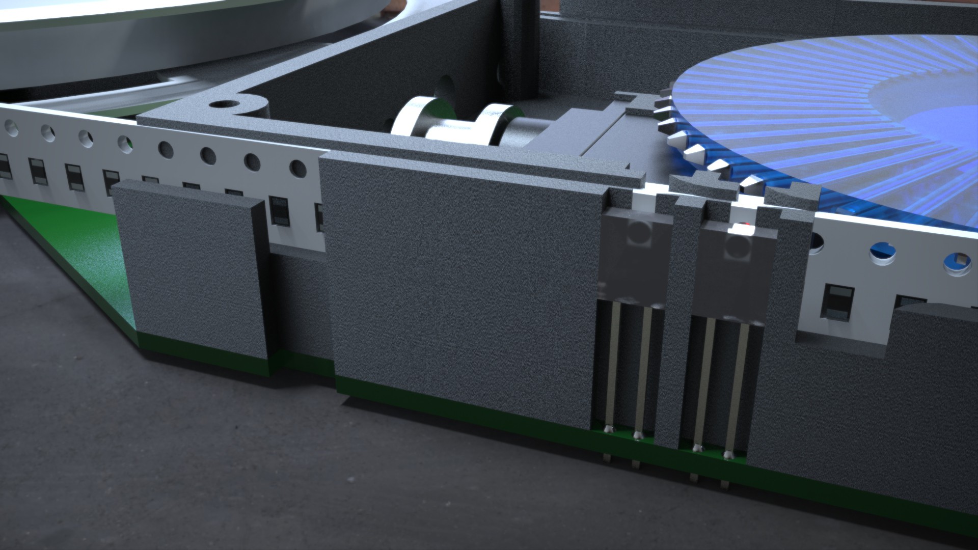
An an alternative i decided to try to detect holes in in the tape. I placed LTE-302 or something similar and led very close to pickup hole and in correct height to detect the hole location. Also i added another pair 6mm away because smaller parts are placed with 2mm spacing. Photodiode output is fed into analog input so it is quite easy to locate different places of holes by software, begin of hole, end of hole, etc. Did some test when feeding real tape with motor and setup was working very fine. Now it is possible to detect end of tape and stuck tape conditions. Those sensors are probably not working with transparent tape, let's see. Magnetic position sensing is maybe the only way to go with those. Also there is now pcb's on bottom side too. top pcb will be just dummy board acting as a cover and reel holder. Thru plated holes of pcb will act as an bearing for gear axle, tin+copper, steel pair should work well as an bearing.
So the feeder will be 18mm thick 4 layer pcb where 2 axis robot and controller is embedded in the middle insulator layer. Very traditional design..
I know that there are many people out there who would like to experiment with automatic pick and placing.
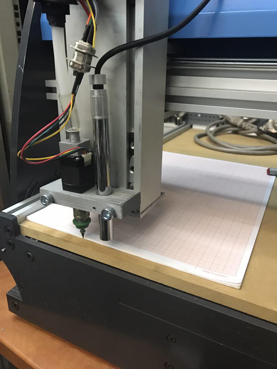
Photo is from very early openpnp tests. Elektor readers recognize the machine from more than decade ago.
I posted this to show that making working pick and placing machine does not have to be complicated. Only two quickly printed custom parts, if you have some frame like this available.
When you get your feet wet, you start to realize where you want to swim.
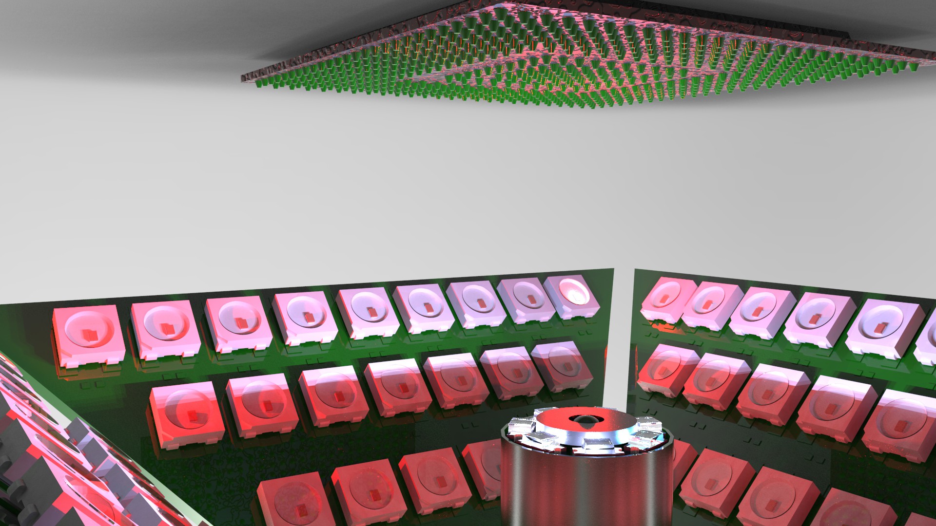
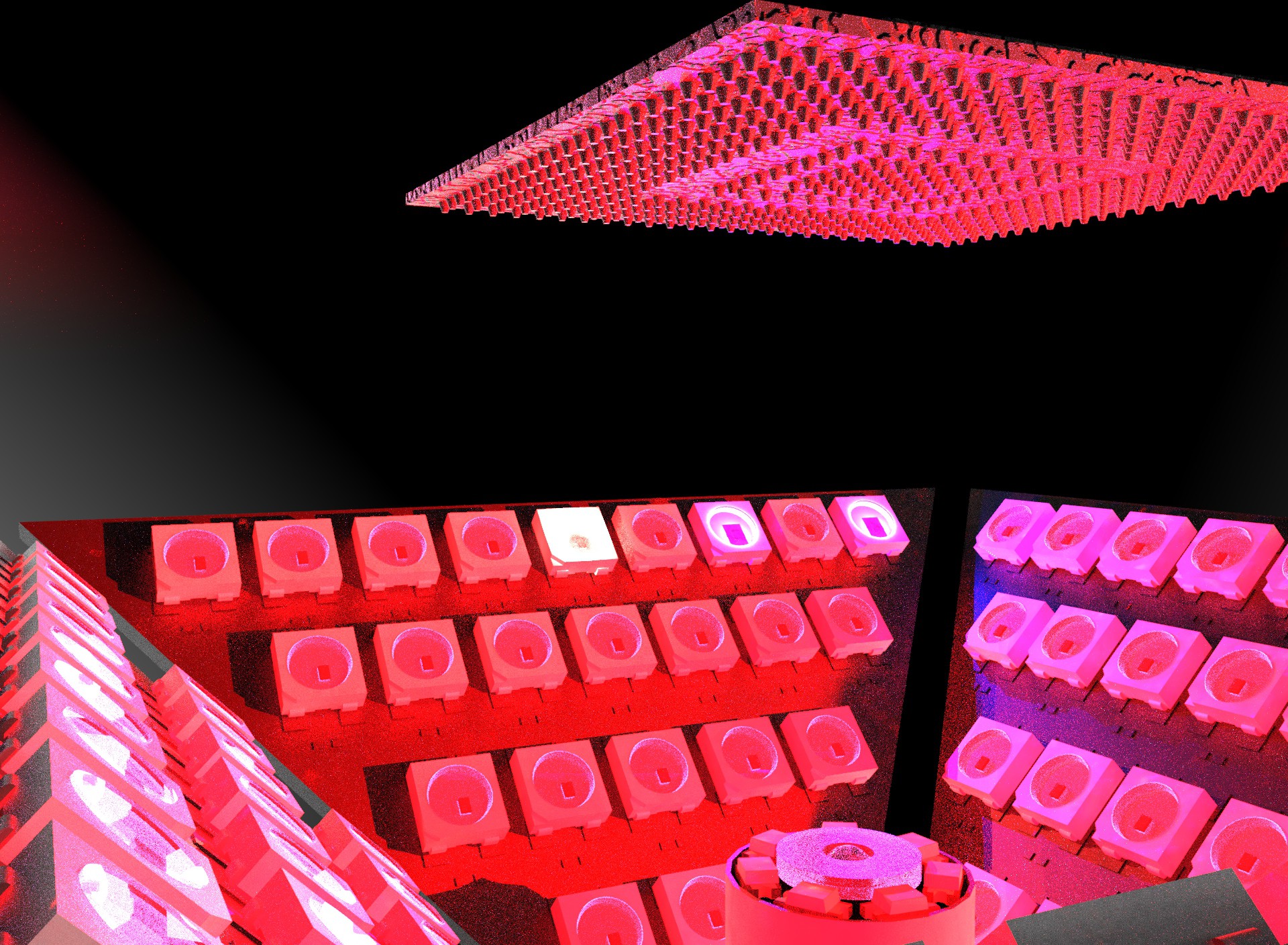
It is obvious that up looking camera needs proper lighting to detect alignment of different components.
i did pyramid shaped light(4 pcbs) that each side has 24 pieces of ws2812b, total 96 leds that each can be controlled by color and intensity. Next task is to add support for those into SmoothieBoard.
Plan is to have own bitstream file for every lighting profile. Profiles can be changed by custom G-Codes.
 Great that there are so many new people following this project.
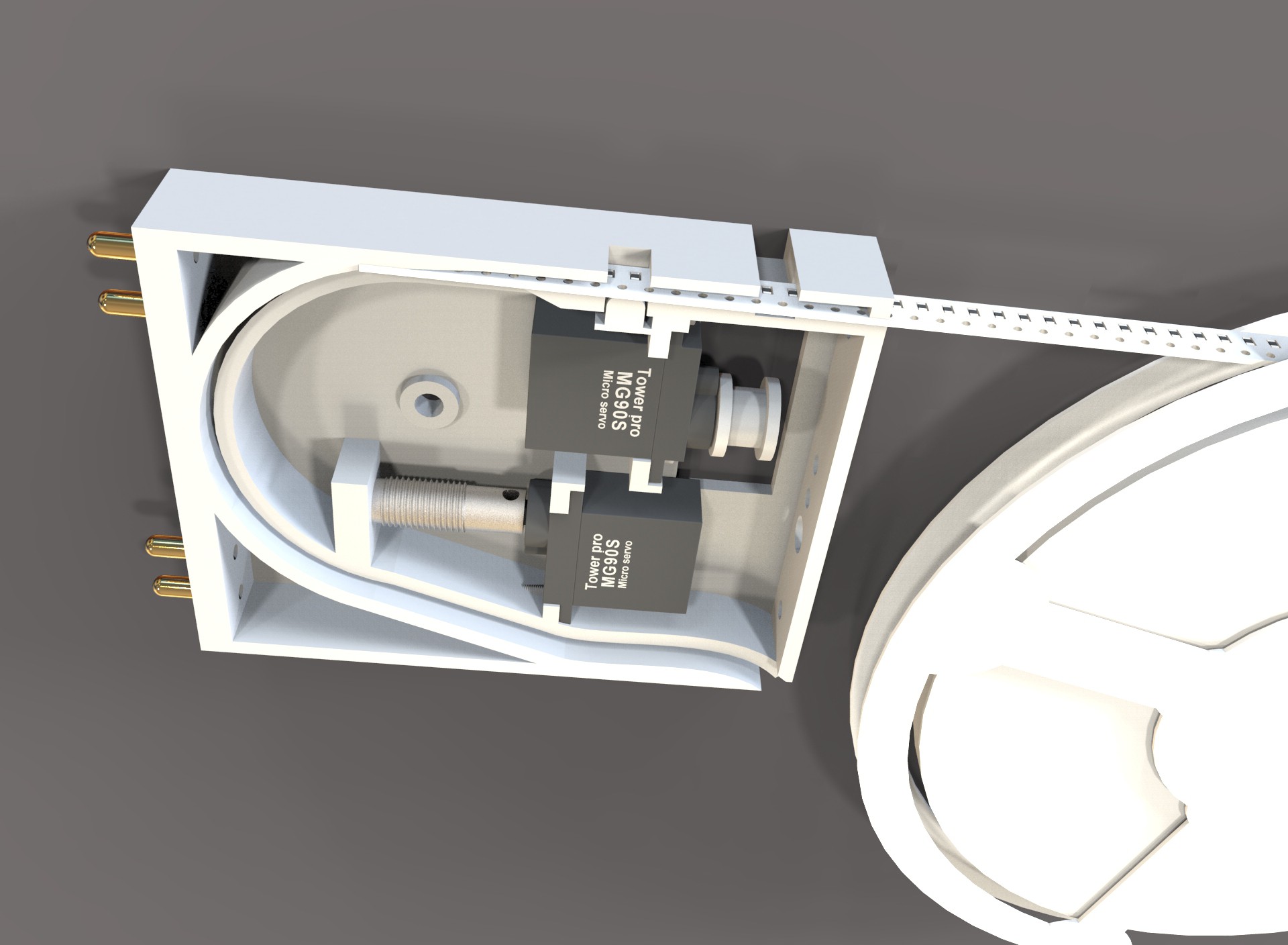
There are numerous changes in feeder design.
I decided to leave the concept of placing tape into gear manually. Now tape is inserted and removed always with the motor. Also added small part under the pickup location to push the tape upward. As you some tapes are thicker than another and tape cannot be loose at pickup location.
Also tape now returns from back. Tape has to bend some amount to travel the route and requires some force for pending. Luckily the feeder is very powerful because of transmission, but i think still fast enough.
Cover of the feeder will be controller PCB.
Also started to think how feeders are connected to machine. Plan is to add "back plane" pcb, that will be electric gateway as well as mechanical locators for the feeders. Every feeder has four 4 mm "banana" plugs that will plug into back plane. Those "bananas" are heavy enough to mechanically locate feeders into their place. So there is no need for separate locator pins and connectors.2 pins will provide power and 2 act as an bus (i2c or rs485). Every reader has it's own address an there will be jumpers or dips for setting it.
Some changes are still needed. Pickup location is for example now too "far".
Just drop message if you tips or comments.
Thanks for your support!!
Create an account to leave a comment. Already have an account? Log In.
Thanks for reminding about the "flying cameras'. That is definitely best way to check component position on nozzle. Need to do some study if there would be some "economical" way to implement such setup :) Thanks!
Really love the feeder design, are the source files available ?
Hi Mika, Any idea what the smallest SMD component size will be that can be placed?
And why did you go for the smoothiboard and not the duet https://www.duet3d.com/?
BG
It looks that 0402 goes without vision alignment. Smaller ones need to use vision alignment that slow down the pickup.
Smoothie works very well with the openpnp and there are many openpnp users there. I have no experience about duet3d.
ok, nice! So OpenPNP works good (only?) with Smoothieboard. One more question, you need to drive 5 motors, correct?
i am sure you can use any g-code capable driver with openpnp, smoothie just worked with default settings. Maybe some other also do. I liked the way how the Smoothie firmware is structured for own expansions. 4-axis is minimum for pnp. 5 when you want to use 2 heads.
...what about using a shop vac or household vac as a high power source?
Thanks,
There might be troubles with the cooling when air flow is limited. Also power usage and noise are pretty high. Now doing some experiments by changing brushless motor into small dc vacuum pumps.
Hello Mika, your smart feeder concept is very impressive! Are you making the build files available somewhere? Do you have an idea of the build cost for each feeder? I have toyed with the idea of modifying my PnP machine to use Yamaha pneumatic CL type feeders, but the cost per feeder is upward of USD $100. Shameless plug for My PnP machine project: https://hackaday.io/project/25437-hot-hot-yushengtech-smt50-openpnp-conversion
Thanks, I like your conversion too. I was very close to go with same route too. I just wanted way to replicate my machine when needed. Sure, commercial feeders can be very expensive. Hard to say about prices of my feeders because those are still in progress, but i have tried to keep prices low and parts should be below 50$ if you are printing yourself. Servos are the most expensive part, i am using now full metal &ball bearing ones that cost around 10$ each. Until design is fully completed, well tested and documented i am not releasing, because i have no resources to support unfinished work. Hope to get there soon.
One more comment about the vacuum and pressure. If the volume and pressure delta can be low why not use peristaltic pump with suitable solenoids on each end of the pump? While the pump rotates the other end creates weak vacuum and the other end weak pressure. Pressure can be zeroed out with suitable profile of the pump or by controlling valves with electronics. For small parts with low mass a weak vacuum should be enough. The tubing also acts as a pressure/vacuum tank.
Fresh Idea, Nice. Now there is more than 1 meter of tube so the need for the vacuum is pretty high. peristaltic pump would need to run very fast.. Placing solenoids close to head would help, but would increase the head mass. Pretty happy with the Aircond service pump, high volume=low pickup times, power for bigger parts also. -- Please tell everybody about all vac pumps you have good experiences. or any other novel sources of vacuum suitable for pnp.
My though was to place the pump on the pickup head or on to the vertical beam as the construction is very light. I know the commercial pnp machines are very fast, but what is your goal with this maker-friendly construction? Another variant would be similar to pump nozzle diesel injection devices, still using continously rotating eccentric lobe but operate a piston instead of squeezing a tube.
Adafruit lists its pump to be capable of creating 500mm/H2O of vacuum, how much you actually need?
brdMaker is actually very fast already and head & beam mass is an issue causing vibrations. Still improving speed, accuracy and reliability so it never going to be cheapest or simplest machine on earth, simply too much metal in it. Hopefully serious alternative to entry level commercial machines. This piston like construction sounds good to me, no wearing tubes. Something railgun like construction running the piston? I don't have yet numbers how much air is really needed, but plenty. Vacuum line is far from perfect. Nozzle tip is steel and leaking well, also nozzle holder is missing seals. Now there are 2 heads so head related air stuff need to be doubled. You are right there is need for smart source of vacuum..
One way to detect the end of reel is to place a light source in mids of the wheel and monitor the light leaking between the pins. As long as the reel blocks it everything is fine. The transparent or translucent reel material is sort of a problem here too. Maybe the simplest way is to add a feeler roller with a micro switch and have the roller to double as a tensioner.
If you are interested to try out the JeVois system i can borrow you some for experiments. I'm a Finn too so this is simple enough given that you are actually located in Finland.
Microswitch as a tape pusher is just a great idea! You are genius! Smartcams like Jevois are close to my mind, so maybe we get a test drive when most urgent things are done. Thanks!
plenty of ideas, nice to hear at least one of them are actually useful :)
Any benefit in using different wavelengths of lights for the camera? Using RGB and UV would allow pattern recognition of the placed parts by their orientation and color pattern. Then use something like JeVois to provide pattern matching in order to verify correct placement. This might require stereoscopic cameras with one with UV filter and one without.
I like you way to look things! I don't have experience when we would benefit from IR. Definitely i will try when facing issues with pure RGB. There is definitely need for better cameras and processing. jeVois looks nice but i would prefer handware with gpu or fpga. I thinks that all jevois things can be done with RPI. Many video pipeline stages can be even pushed into GPU. I have done stereo procesing on rpi(CM1) GPU and can say it's very powerfull platform. think that i will start experiments with rpi when needed, with proper lenses and lights you can get very good results. Also there is path to dual cams if needed. Thanks Jive for your great points!
There is very good CV functionality in OpenPNP. For basic pnp operations usb/webcams connected to pc works just fine. Better/smart cameras are needed only for custom or very high speed operations.
Love your project! Rooting for you to come through with that feeder :)
I would not be doing this without your efforts. More than thanks!
great project! I like your custom feeder design, I would love to borrow it for when I build one of these https://hackaday.io/project/9319-diy-pick-and-place and by build I mean heabily modify as I go so its a completely different machine lol
Thanks. That's why we are here :) 9319-diy-pick-and-place was mental starting point for brdmaker also. All respect to anthony.webb!
Become a member to follow this project and never miss any updates
 Peter Wasilewski
 Lance
Lance
 ottoragam
 Darryl.N
My Samsung CP20 uses a laser scanner (LED line grating plus single line image sensor) to scan the outline of the part while it is in transit to it's placement position. It can scan in 3D by rotating or lifting the part into the laser's path. This means it can correct for alignment/rotation as its being moved and not require an up-facing image check. Awesome for small 0402s and less, SOTs and ICs. I barely use the up-facing camera. It is also used to check that the nozzle picked up successfully as it can scan the nozzle too. If you want more info let me know. I love your design, awesome work!