 edensrock
-
First Batch of ERASynths are Shipped and Sales Have Started
04/19/2018 at 15:46 • 0 commentsWe are happy to announce that our first batch of ERASynths were nicely packaged and shipped from İstanbul to Crowd Supply’s warehouse.
There are extra units. So, ERASynths are now in-stock. The order can be made and the shipment will be done immediately.
https://www.crowdsupply.com/era-instruments/erasynth![]()
-
Implementing Analog Modulation Functionality in ERASynth
06/15/2017 at 20:55 • 0 commentsOne of the most frequently asked questions about ERASynth was about availability of analog modulation functionality. When we designed ERASynth’s current revision, we payed attention to do it such that basic analog modulation types could be implemented by software. We were planning to leave to users, but since we received so many questions, we decided to work on it. We have implemented basic AM and pulse. For now we can say: AM rates up to 10 kHz for external input and AM rates up to 2 kHz when using internal generator can be generated with ERASynth. Please watch the video below to see a quick demo:
FM Functionality and Diagnostics in ERASynth
We’ve finally added FM functionality to ERASynth.
When it comes to microwave synthesizers, there are several ways of implementing analog modulation functions. These are very nicely outlined in the article “Implementing Modulation Functions in Microwave Frequency Synthesizers” by Chenakin.
During the past week, It has explored different methods of FM signal generation. Please watch the following video for a quick demo. We also show the “Diagnostics” feature of ERASynth in the video.
-
Why Arduino Due?
06/15/2017 at 20:52 • 0 commentsWe selected Arduino Due for ERASynth for a number of reasons: Its processing power, number of available hard SPI LE pins, availability of a many GPIO pins, and its natural integration with the ubiquitous Wi-Fi module ESP8266.
Powerful MCU
When we started the design of ERASynth, we could use any of the many open source projects for the control of our signal generator project. We evaluated our options and realized Arduino Due had the enough horsepower to support all of the calculations. CPU power was an important metric for us, because we had set out to create an agile signal generator. When you are aiming to achieve frequency-switching speeds under 100 µs, you do not have a lot to waste on the calculations. With its 84MHz ATSAM3XE, Arduino Due was the perfect choice for ERASynth.
Number of Hard LE Pins
Serial Peripheral Interface (SPI) is a serial protocol that uses four lanes for duplex communication between a master and a slave device. When it comes to PLL synthesizers, SPI is now the industry standard. Almost all of the state-of-the-art PLL ICs provide three or more pins for configuration by a host microcontroller using the SPI protocol. The naming on the pins can vary but the functionality stays the same. Here is a list of the SPI pin names encountered in PLL datasheets:
- Master Out Slave In: MOSI, DATA, SDATA, SDO, SDIO
- Master In Slave Out: MISO, SDI, SDIO, MUXOUT
- Clock: CLK, SCLK, SCK
- Slave Select: SS, CS, LE, SEN, CSB
Current revision of ERASynth made use of four different PLL ICs: ADF4002, HMC830, ADF4356 and LTC6945. The final prototype will use ADF4002 and LMX2594. All of these ICs require SPI communication for programming. Arduino Due provides one SPI bus with three hard LE pins. Hence, one can program up to three separate PLL ICs using the Arduino Due. Three hard LE pins are sufficient for most purposes. In the case where there are more than three slave devices (as in the case of ERASynth rev2), soft LE pins can be used. Soft LE pins are normal GPIO pins used for slave selection. There is a significant amount of delay associated with soft LE pins, i.e., SPI transactions using hard LE pins are much faster compared to soft LE transactions. For an ultra-fast RF synthesizer as ERASynth, availability of hard LE pins in Arduino Due were advantageous. We used all three hard LE pins for the ICs for which speed was crucial. HMC830 (tunable reference generator), ADF4356 (main VCO), and LTC6945 (main PLL) were programmed using the hard LE pins. Here is a screen short of the SPI transactions for a frequency of 4 GHz:
![]()
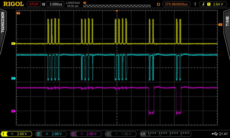
SPI transactions for a frequency change command in ERASynth
As you can see in the figure above, one frequency change command requires 16 bytes of SPI transaction. We were able send 16 bytes in less than 30 µs.
A Plethora GPIO Pins
Wideband and high dynamic range RF circuits utilize many control elements such as switches and attenuators to provide the wide bandwidth and dynamic range. In the design of ERASynth, there are multiple switches and several attenuators requiring more than 20 GPIO pins. Luckily, Arduino Due provides more than enough GPIO pins.
Natural Integration of ESP8266:
One of the defining features of ERASynth is its Wi-Fi connectivity thanks to the on-board Wi-Fi module ESP8266. Before starting the design of ERASynth, we did not have any prior experience in using ESP8266. We were able to get started quickly as there were lots of code available. Arduino made our job very simple. Getting ESP8266 into action was just a matter of loading a new library. Using Arduino IDE, we can program ESP8266’s flash without even opening the ERASynth enclosure. We are using the same mini-USB port to program both ATSAM3XE’s flash and ESP8266’s flash. This was all possible thanks to strong community behind Arduino and ESP8266. Programming ESP8266 using the Arduino IDE is not a trivial achievement considering Dave Jones published a video for it just recently.
What did we improve?
We did not just bluntly copy Arduino Due’s schematics and the available open source codes. We did improve several aspects in both hardware and software.
Upgrading to BGA Package
There was one drawback in selecting Arduino Due for the control of ERASynth. The MCU in Arduino Due is ATSAM3X8E by Atmel (now owned by Microchip). Arduino Due board uses the LQFP version of the ATSAM3X8E, which is 22 mm * 22 mm. Hence, if we had used the LQFP packaged version of ATSAM3X we would have to allocate 484 mm2 of precious board area. Our PCB stack-up was expensive so we decided save it wherever we could. We selected the BGA version, which only occupies 100 mm2 of board area. Going from the LQPF to BGA package was not a very challenging task. There were only a couple minor differences between the two packages. Nevertheless, we had to be very careful.
Speeding up the soft SPI:
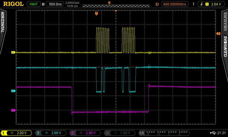
As we mentioned above, when the hard LE pins are not sufficient, GPIO pins can be utilized as soft LE pins. In Arduino, a soft LE pin may be implemented using the usual digitalWrite() function. However, this function wastes several microseconds of time. Here is an oscilloscope screen showing the waveforms for a soft LE using the digitalWrite():
![]()
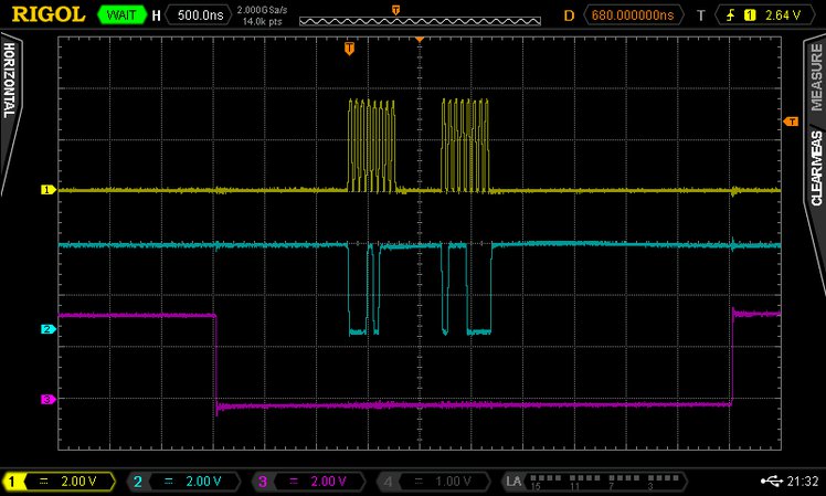
Soft LE using the digitalWrite()
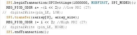
As you can clearly see in the picture above, there is about 1.25 µs of time difference from the falling edge of LE to the first rising edge of the CLOCK. There is even more time –about 2.5 µs– between the last falling edge of the CLOCK and the rising edge of the LE signal. A total 3.75 µs of time is wasted since there is no data being sent or received during these time slots. This wastefulness is per LE cycle. When there are 10 LE cycles, it scales up to 37.5 µs, which is a significant amount to waste for an RF synthesizer that aims to achieve a total lock-time of 100 µs. Therefore, we modified the soft LE as shown in the code snippet below:
![]()
With code shown above, the SPI waveforms look like the following:
![]()
Accelerated soft LE
As you can see in Figure 3, by directly manipulating the port pins, we were able to save more than 2.5 µs of time per LE cycle.
Inclusion of Buffers, FRAM and Temp Sensor:
We further improved upon Arduino Due by bringing an FRAM, many buffers and a temperature sensor on-board. We needed some form of storage to keep the calibration values. An EEPROM is the usual choice, but we selected FRAM for its longer durability and faster access times. RF circuits are extremely vulnerable to MCU noise. We did not take any risks. We buffered and filtered each and every control line.
-
Testing the ERASynth Architecture with LMX2594
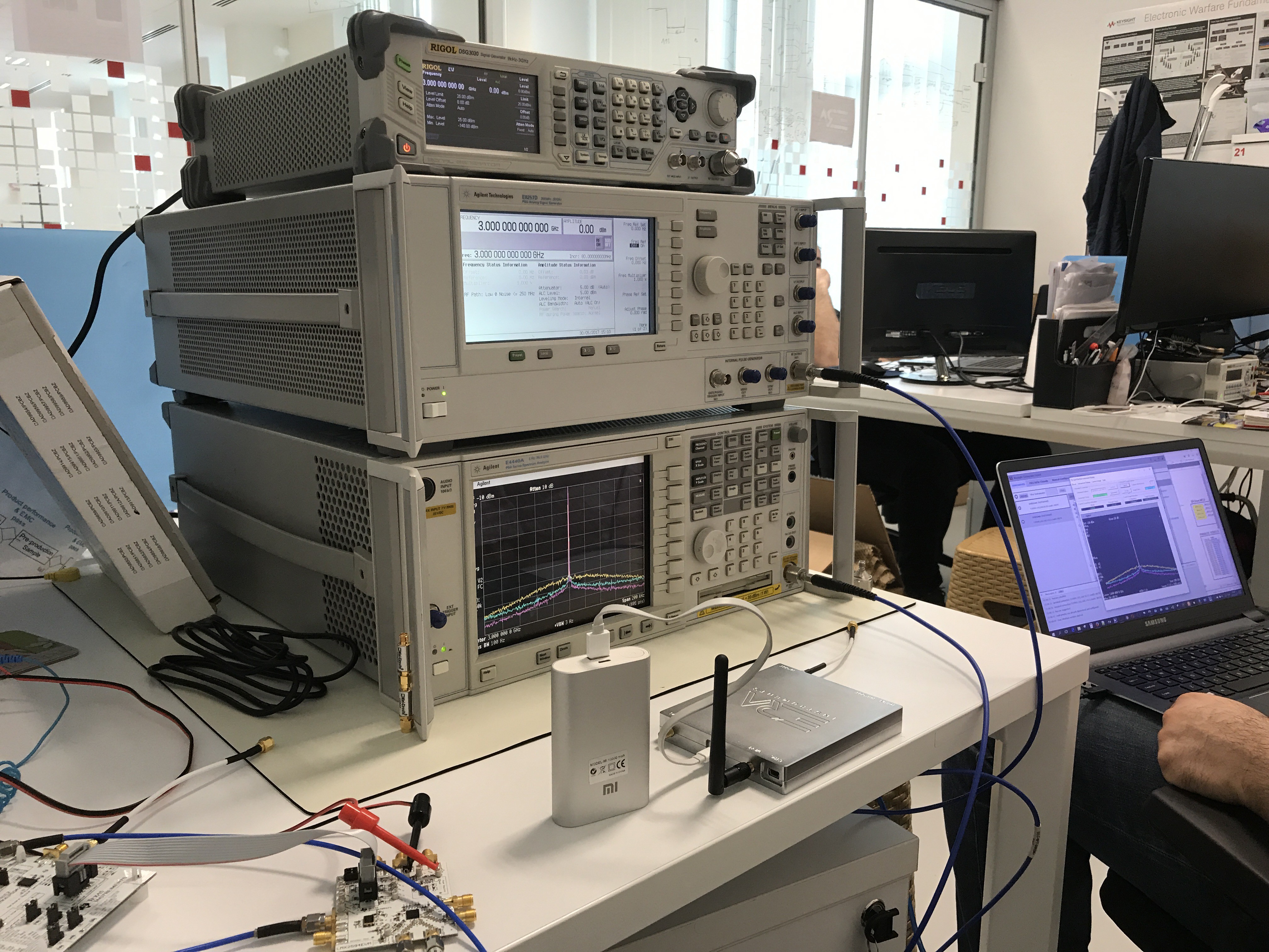
06/07/2017 at 09:48 • 1 commentAs we mentioned in the previous updates, we are going to use LMX2594 in our final prototype. TI has just released the LMX2594 a few months ago. There is a relative small risk in using a newly released IC in the design. We wanted to mitigate that risk. We ordered two copies of the eval board (LMX2594EVM) and gathered a test setup to mimic ERASynth’s architecture. We needed two copies because ERASynth’s design uses one PLL for the reference generation loop and another PLL for the main synthesizer.
Test Setup
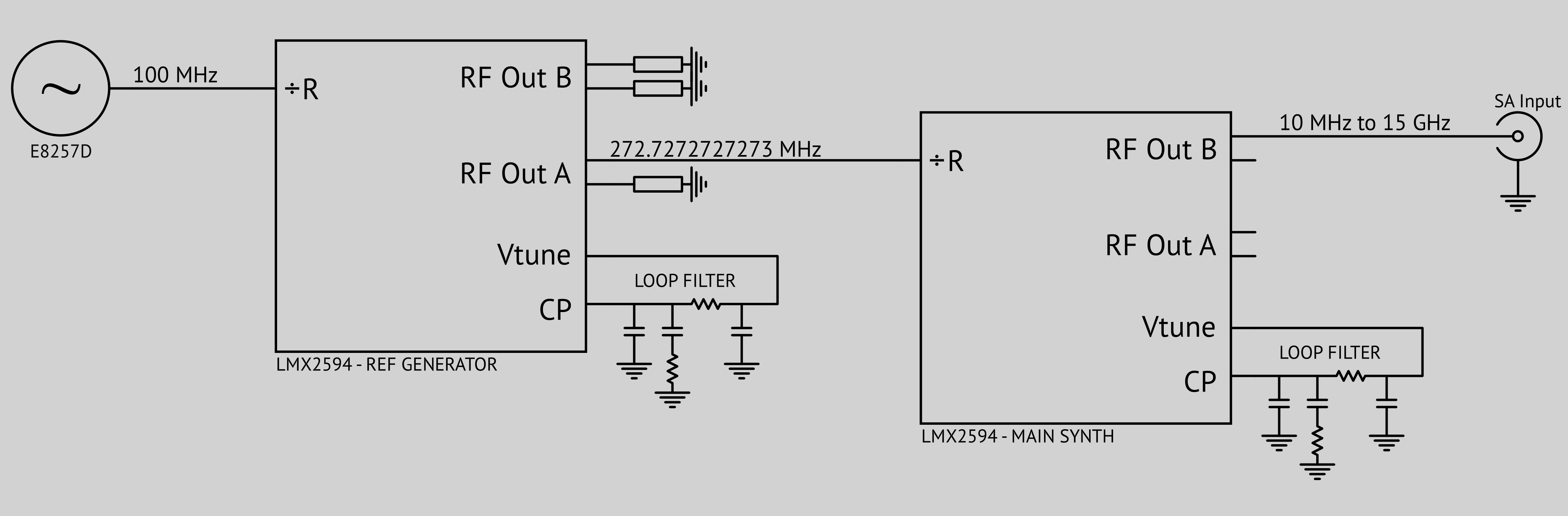
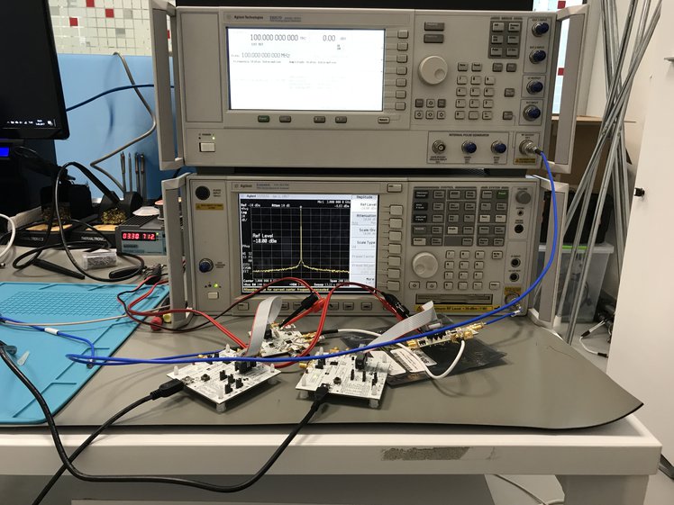
After establishing the necessary RF/DC/Control connections using appropriate cables, we powered up both of the eval boards using a low-cost switch-mode power supply (Gophert CPS-3205). LMX2594 requires only a single voltage rail of 3.3 V and draws about 400 mA. We disabled the on-board TCXOs of each board and supplied a reference of 100 MHz from the E8257D to the first LMX2594EVM (the reference generation loop). Normally signal generators are not as clean as crystal oscillators, but E8257D was sufficiently clean at 100 MHz. We fed the output of the first LMX2594EVM to the reference input of the second LMX2594EVM. Here is a block diagram and an actual photo of the test setup:
![]()
We drove one LMX2594 with another LMX2594 for ultra-low spurious.
![]()
Photo of the Test Setup
As the block diagram shows above, PFD comparison frequency of ERASynth’s main loop will be around 270 MHz in the final prototype. This is a relatively high comparison frequency but LMX2594 can do it. In integer-N mode, LMX2594’s PFD rate can be set up to 400 MHz but there is a limit on the N divider (N ≥ 28), that is why we selected PFD rate as ~270 MHz.
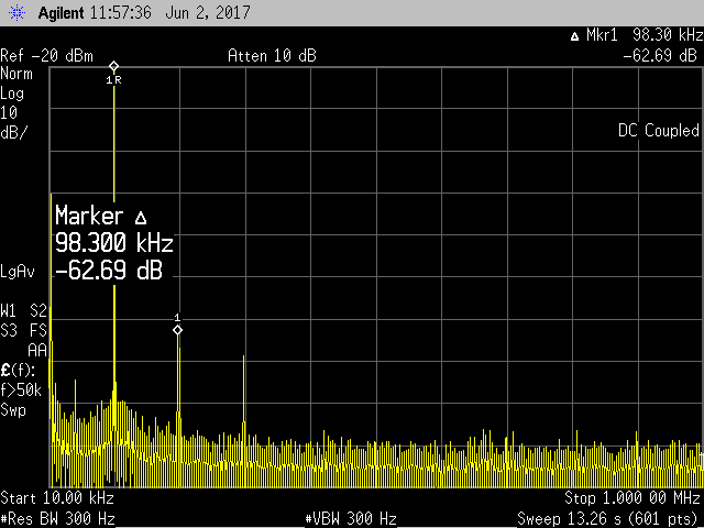
Test Results
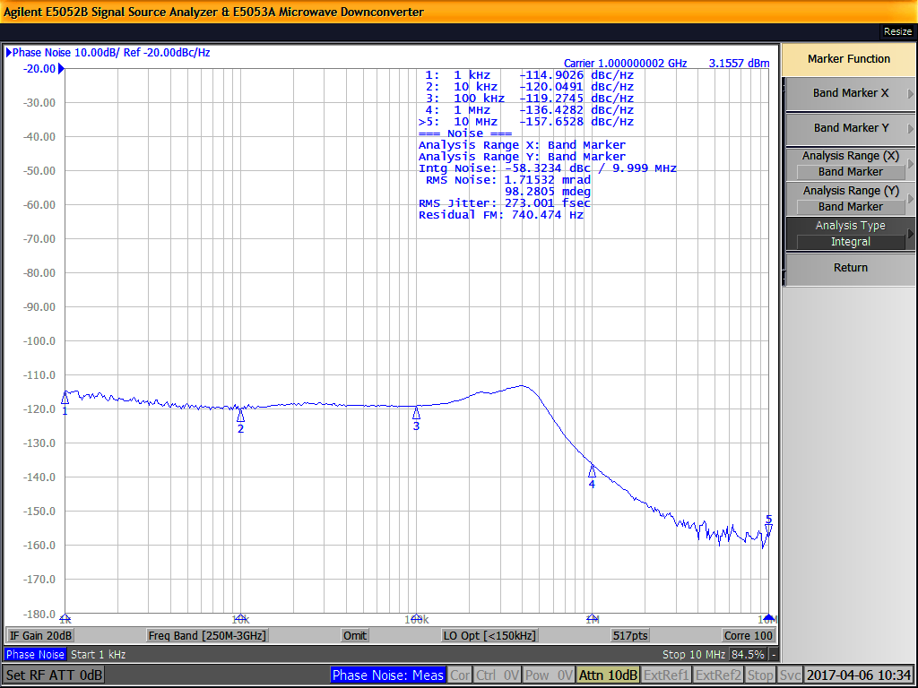
We measured a phase noise of -112.7 dB at 3 GHz, 10 kHz offset using our PSA spectrum analyzer. This value is a couple of dBs higher that what we were expecting. Obviously, there is some (about 3 dB) phase noise contribution from PSA’s tuning local oscillator. For exact measurement of such a low phase noise, we would need a signal source analyzer (SSA), which is a very expensive test gear. We took the phase noise graph shown in our campaign page with an SSA (courtesy of İTÜ’s VSLI lab).
We must say TI has done a great job in LMX2594. We went the extra mile in our second prototype just to get a phase noise of -120 dBc/Hz at 1 GHz. We had to drive ADF4356 with HMC830 while using LTC6945 as the external PFD. The people at the clock and synthesizers division of TI were able to squeeze even more performance into a single chip. What is more fascinating is that you can even feed this chip (LMX2594) with a switch-mode power supply.
Conclusion
Using two LMX2594 eval boards, we were able to verify the performance of ERASynth’s final revision to the best capability of our test equipment.
-
Use of a DDS in the LF Path
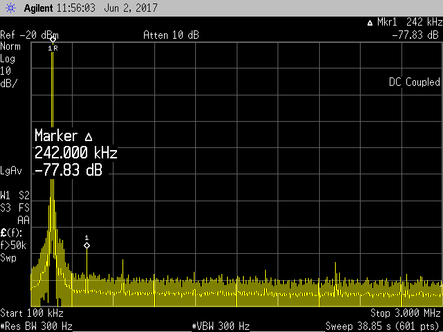
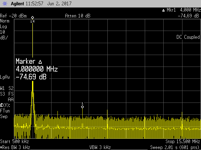
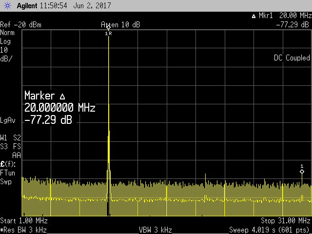
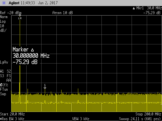
06/02/2017 at 21:34 • 0 commentsWe decided to use a DDS for the low frequency (LF) path. ERASynth’s current prototype does not have the LF extension. For the final revision, we were pondering our options: DDS or adjustable divider. There are several adjustable dividers on the market by different vendors and they are cost-effective compared to DDS ICs. Dividers generate waveforms with digital circuitry; their outputs are rich in harmonics. In addition, they tend to consume more power than DDS ICs.
DDS ICs also generate waveforms with digital means, but they have a built-in DAC to convert the digital waveform to analog domain. After evaluating AD9913 –a 250 MSPS DDS IC by Analog Devices– we decided to use it for the LF path. With AD9913, we can easily go down to 250 kHz or even below. AD9913 provides significant power savings since it consumes no more than 70 mW in single tone mode. It also provides better overall harmonics performance compared to divider ICs
![]()
![]()
![]()
![]()
![]()
-
Harmonics Levels of ERASynth
06/01/2017 at 16:55 • 0 commentsWe have received many questions regarding ERASynth’s harmonics spec, which is -10dBc in the campaign page. Many people were wondering why ERASynth’s harmonic levels were not as good as its phase noise or lock-time. There are several reasons:
The harmonics stem from the signal generation mechanism and we cannot do much but use a lot filters if we want to reject them. ERASynth uses highly integrated PLL ICs that have built-in VCOs. These types of ICs usually contain an octave VCO in the GHz range and generate the lower frequencies by dividing the fundamental VCO down. For example, our second revision used ADF4356 by Analog Devices. ADF4356 has a fundamental VCO range of 3.4 to 6.8 GHz. Frequencies below 3.4 GHz are generated by utilizing digital dividers, which produce square-like waveforms. Bench top equipment also generate low frequencies by using digital dividers, but they also provide a lot of filtering by using switched filter banks after the dividers. Switched filter banks are expensive and bulky. In fact, a filter bank to improve the harmonics level of ERASynth to bench-top levels would probably cost more than several times ERASynth itself.
You cannot improve phase noise (at close offsets) using an external filter but you can improve harmonics. Harmonics can be easily rejected with external filters. Many RF people have a variety of connectorized filters (usually by Mini-circuits) in their labs. When there is a test requiring stringent harmonic rejection levels, they use external filters (even with bench-top equipment). For example if you want to measure SFDR of a high resolution ADC (>12 bits), you have to use an external filter to make sure that measurement is not limited by the signal generator. That is the reason why some bench-top equipment manufacturers provide options for enhanced harmonic rejection. For example, option E8257D-1EH by Keysight improves the E8257D’s harmonics by more than 25 dB. But it costs $5304.
It would only be fair if we compared ERASynth to competitors in its own league. Many of our competitors utilize ADF5355 or equivalent PLL ICs to go up to 13.6 GHz in frequency. Since the signal generation mechanism is the same, we believe competitor harmonic levels are comparable to ERASynth. However, when it comes to sub-harmonics, ERASynth’s final revision will surpass competitors. We are using LMX2594 by Texas Instruments in ERASynth’s final revision. LMX2594’s fundamental VCO range is 7.5 to 15 GHz. Unlike competitors, we do not need any doublers to generate the upper frequencies. Contrary to harmonics, subharmonics may cause problems.
Lastly, harmonics are not always a bad thing. They are even helpful in some situations. For example, when driving a mixer, the more square-wave-like LO is, the lower the mixer’s noise figure. When driving an ADC or DAC as a clock source, the more square-wave-like the clock is, the better the slew rate. The better the slew rate, the better the jitter is. The better the jitter, the better the ADC or DAC is.
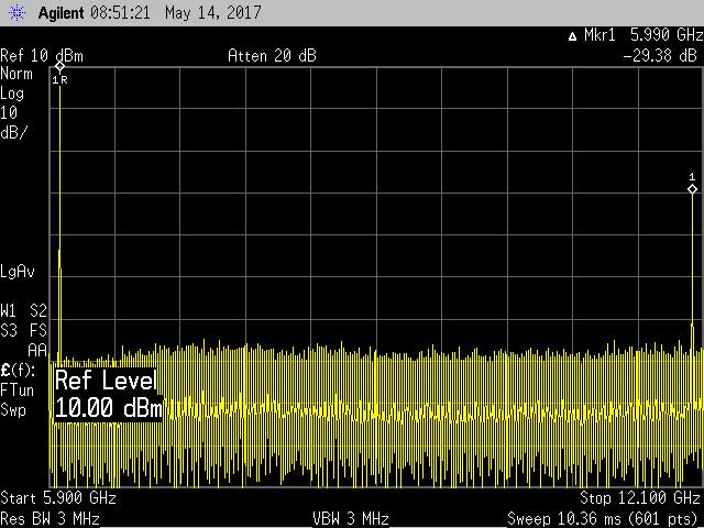
The typical -10dBc spec on the campaign page has some margin in it. We haven't fully characterized the harmonic levels, it will be better at some frequencies depending on the power level. Here are some measurements from our current prototype:
Harmonic level @6GHz_10dBm
![]()
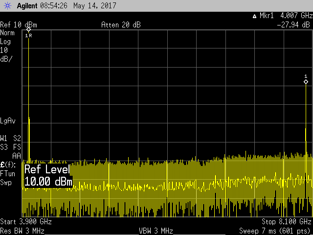
Harmonic level @4GHz_10dBm![]()
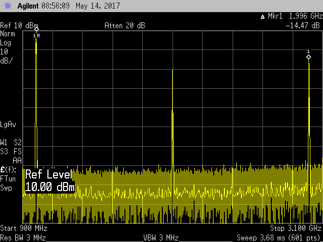
Harmonic level @1GHz_10dBm
![]()
-
ERASynth vs Rigol DSG3030 vs Agilent E8257D
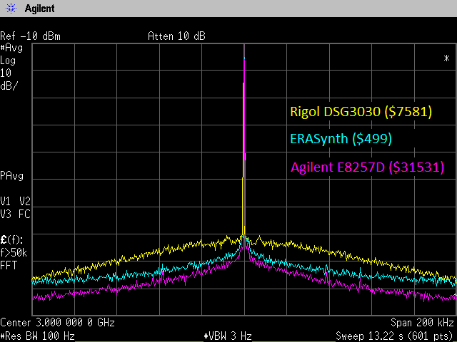
05/31/2017 at 12:46 • 0 commentsIf we were to name one area where ERASynth truly excels at, it would be the pedestal phase noise. (phase noise at offsets from 1kHz to 100kHz)
A signal generator’s pedestal phase noise has different impacts on the system depending on the application. For example, when used as a local oscillator in a receiver application, pedestal phase noise degrades the receiver sensitivity. When used as a clock source in a data converter, pedestal phase noise (together with close-in phase noise) determines the jitter, which ultimately effects the converters dynamic performance.
We carried out a test to compare ERASynth to a couple of bench-top signal generators available in our lab. Here is the result:
![]()
The graph above is obtained using this setup.
![]()
-
Amplitude Accuracy of Calibrated ERASynth
05/30/2017 at 20:00 • 0 commentsOpen-loop Calibration:
It has been developed a search algorithm for finding the optimal attenuator settings for a given power level. It is used U2001A USB power-meter by Agilent for calibrating the prototype. This power-meter works from 10MHz to 6GHz and measures power levels between -60 to +20 dBm. We have ordered a new power-meter that will measure up to 26.5 GHz, it is on its way to Turkey. Once we get our new power-meter, we will be able to calibration beyond 6 GHz. After the calibration, amplitude uncertainty is below 0.5 dB and setting resolution is 0.1 dB.
Quick demo of REF IN:
We also show a quick demo of REF input, showing a 1 GHz signal move on the spectrum analyzer when REF input is switched between internal and external.
-
Isolation of RF Output from on-board Wi-Fi Module
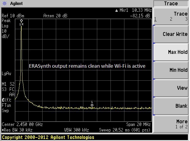
05/30/2017 at 19:58 • 0 commentsWe received some questions regarding the WLAN signals coupling to the RF output. Some people were concerned that phase noise would increase with WLAN module (ESP8266) active. Our tests show that there is no need to worry about WLAN. First of all, whether you use the on-board WLAN or not, WLAN signals are all around us. Secondly, we have taken very serious measures to cope with all kinds of couplings and leakages on the board. As you can see in the detailed PCB picture on the campaign page, ERASynth PCB is partitioned to protect sensitive areas from the outside world and from the other noisy areas on the board itself (such as switch-mode regulators, MCU etc…). There is a tremendous amount of filtering on every supply and control line. The picture below shows ERASynth’s RF output connected to a spectrum analyzer while the WLAN module is activated.
As you can clearly see in the picture above, on-board WLAN signals are suppressed more than enough. With that said, if you are still uncomfortable with the WLAN interface, you can disable it completely using the serial interface.![]()
-
It's more than an App
05/17/2017 at 11:59 • 0 commentsQuick demo of the web GUI
ERASynth's web GUI is almost complete. We had some problems with the WLAN module ESP8266. For some reason, the server on ESP8266 was too slow with some of the browsers. It was very fast on IE/Edge and very slow on Firefox and Chrome. Similar issues have been observed by other users of ESP8266 in the open source community. We had to debug this issue for a long time, now the web GUI is incredibly fast as you will see in the demo video below. It is almost an app, it feels like an app. Actually it is better because it works on all modern web browsers.
ERASynth
Open-Source, Arduino-Compatible RF Signal Generator with Wi-Fi Connectivity