 alexwhittemore
System Overview:
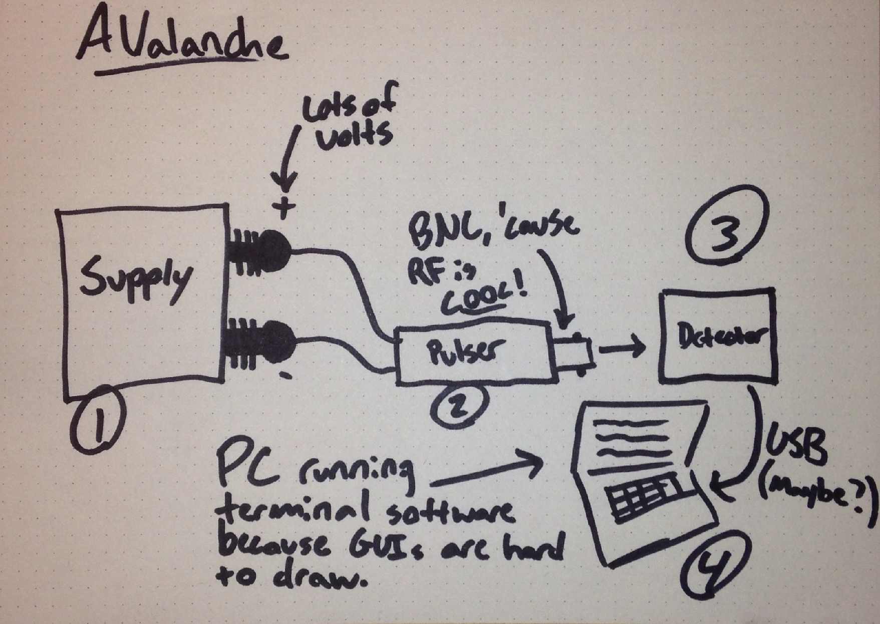
At a broad level, a HV power supply feeds an avalanche-biased transistor. This results in an output of indeterminately repetitive pulses with random timing and extremely fast rise time/high bandwidth. These are (optionally) fed into a high-speed detector for the purpose of timing the duration between pulses, and perhaps for measuring other parameters. This detector is hosted by a PC running software to make the raw and/or processed data available via API.
Power Supply:
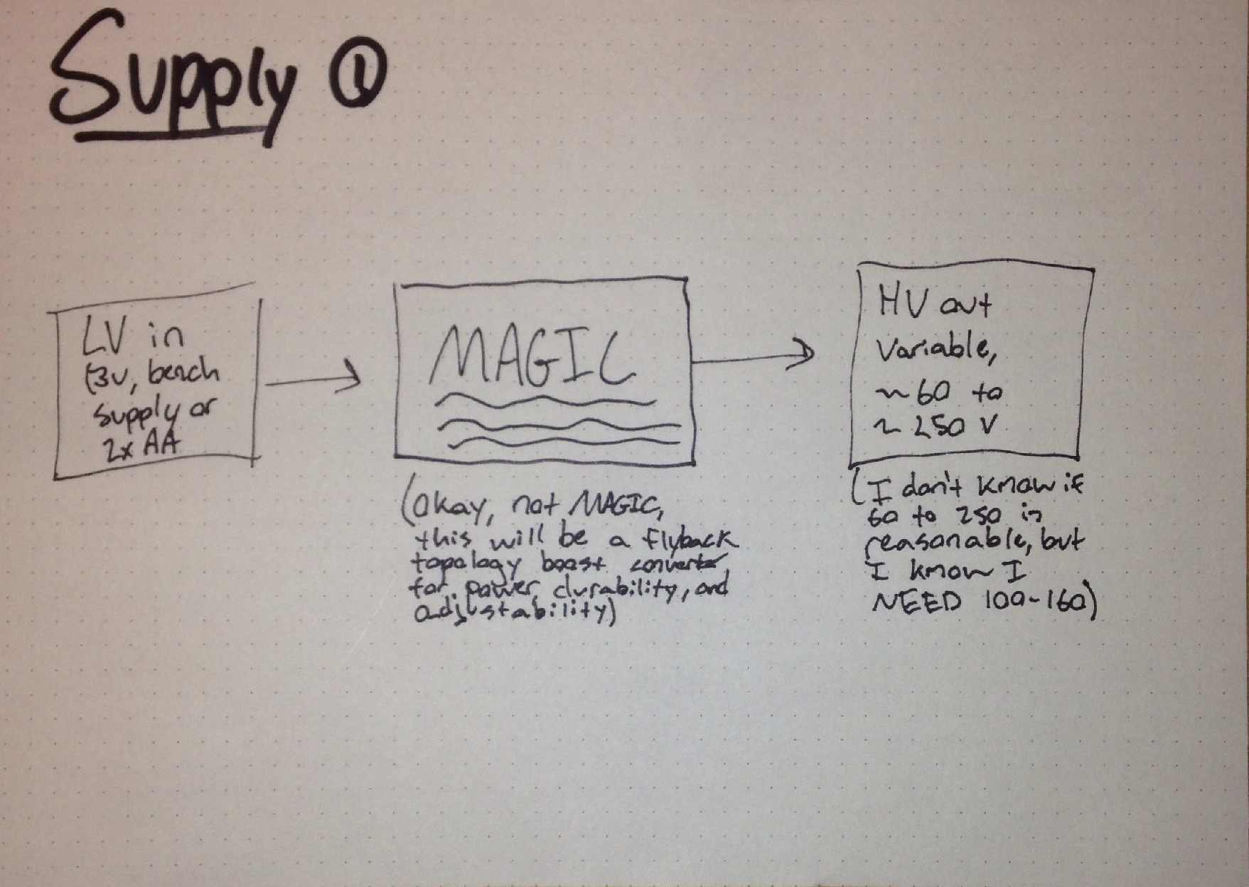
At present, a 150-or-so volt power supply is created by using two external supplies, one 5V and one on the order of 12V. A 5V square(ish) wave is generated by a 555, fed into a buffer and inverter to create a cleaned up square wave and its compliment, and then these are fed into a SN754410NE quad half H bridge to create a push-pull output of the second (12V) supply. This is multiplied by a 7-stage Cockroft-Walton multiplier to around 150V. I do not like this topology for a number of reasons and expect to replace it with a variable, single-supply flyback circuit.
Pulser:
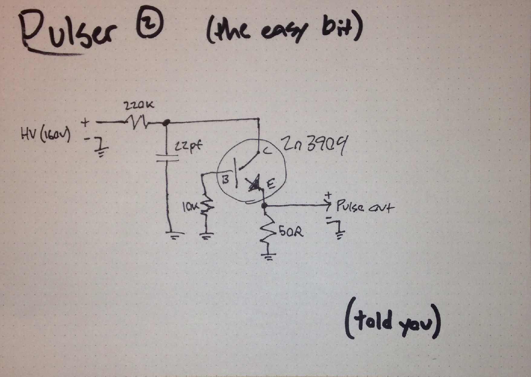
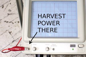
The ~150V out of the supply is used to drive a 2n3904-based Jim Williams avalanche pulse generator. The output is a very fast pulse (faster than my 100MHz scope can measure accurately, a rise-time measurement shows a bandwidth of 240MHz) of about 40V (again, this may be lower than the true output voltage given my scope's bandwidth limitation).
The theory of operation here is reasonably simple: when you greatly reverse-bias a PN junction, you approach a region called "avalanche breakdown." In this region, a small number of electrons will, probabilistically, cross the junction by mechanisms such as tunneling, and will thereby open the junction for further current. This has an additive effect and thus the breakdown process happens on extremely short timescales. The current caused by this breakdown is very high, in this design on the order of an amp, which flows through the 50 Ohm emitter resistor and to the output. However, once current is flowing, it will continue to do so until the junction overheats and breaks. This creates the need for the 220k supply resistor and the 22pf supply cap. The resistor prevents a dangerous amount of current from being sourced through the device by the supply, where the 22pf capacitor holds all the charge necessary for the momentary 1A current. Once the avalanching transistor has drained the capacitor, the collector is then at a low voltage and avalanche current stops. This gives the 22pf capacitor a chance to recharge and the cycle begins again the next time the device avalanches. The 10k base resistor to ground is to ensure that the transistor stays off with the exception of avalanche operation.
Detector:
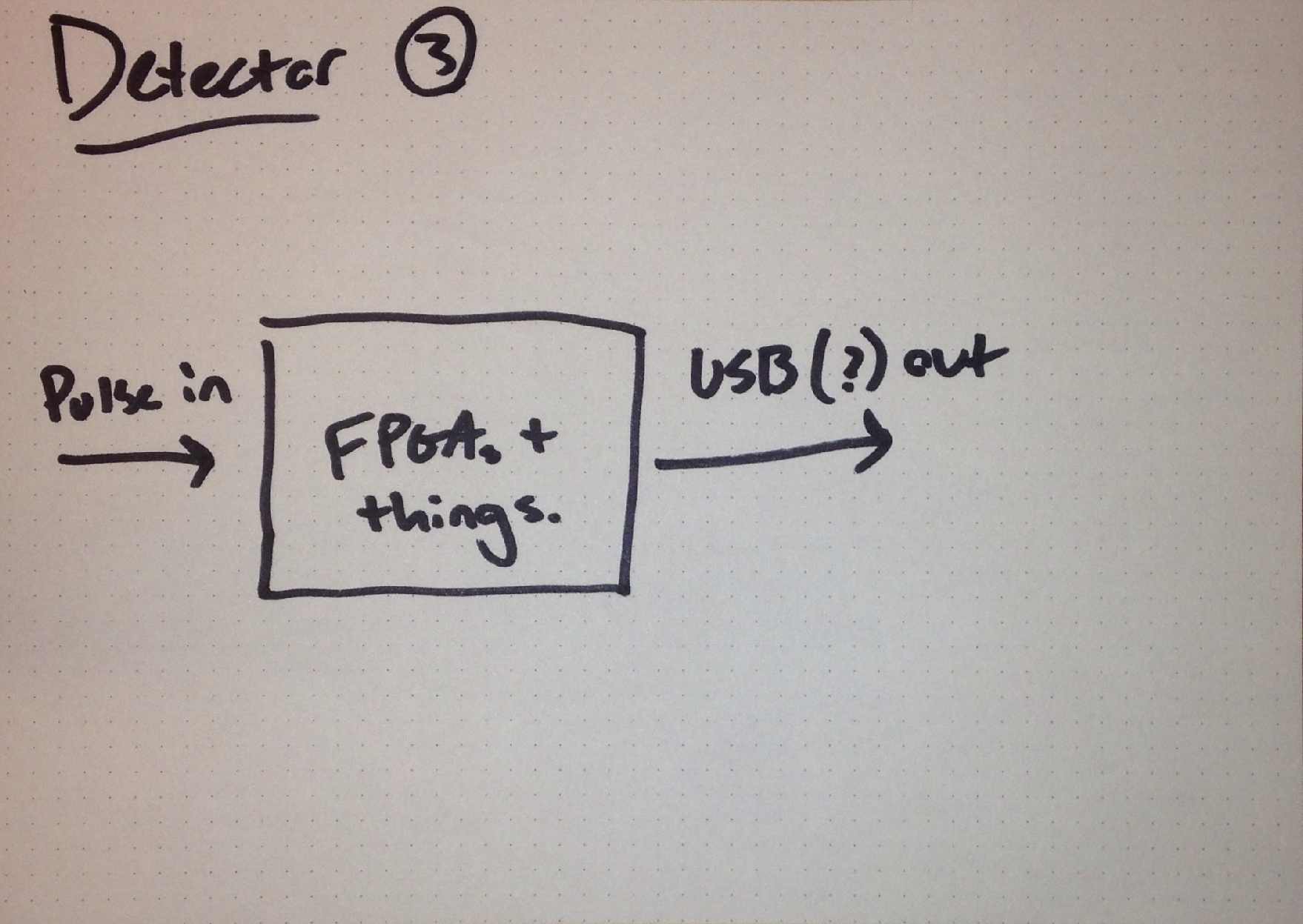
The detector portion is very much on the drawing board still both in design and fundamental definition, however there is one concrete requirement. It will be required to accurately TIME the duration between pulses, as this is a fundamentally random variable. The distribution of durations is interesting to me experimentally as a function of supply voltage and also as a source of random entropy for cryptographic applications.

Software:
Naturally, for the detector to be useful, there must be a way to collect and use the data it gathers. At the simplest, this could take the form of some Python code reading data out of a serial port-connected microcontroller in the detector. This is a very likely route. Additionally, I expect to make a web-based API available so that, for example, an organization could deploy this hardware locally and query it for entropy over a local network connection. In practice, hardware random sources exist, and even high-quality open source ones. But then "practicality" is hardly a design motivation here.


 Yann Guidon / YGDES
 Szoftveres
 Jakob Wulfkind
 robert.c.baruch
Amazing to see this project it looks like a very good power supply project I need more information about it to add this knowledge in my rudn enclave project you can see here.