matt venn
-
PID loop tuning and results
11/03/2014 at 15:32 • 0 commentsI finally got round to some testing and loop tuning. I did some no load tests where I changed the speed, and some tests where a load was applied at 2 different RPMs.
The graphs are produced by a python library called matplotlib that can do animations, so I got to see these happening realtime - which made loop tuning a lot easier. The program is called plotter.py and is in the code repo.
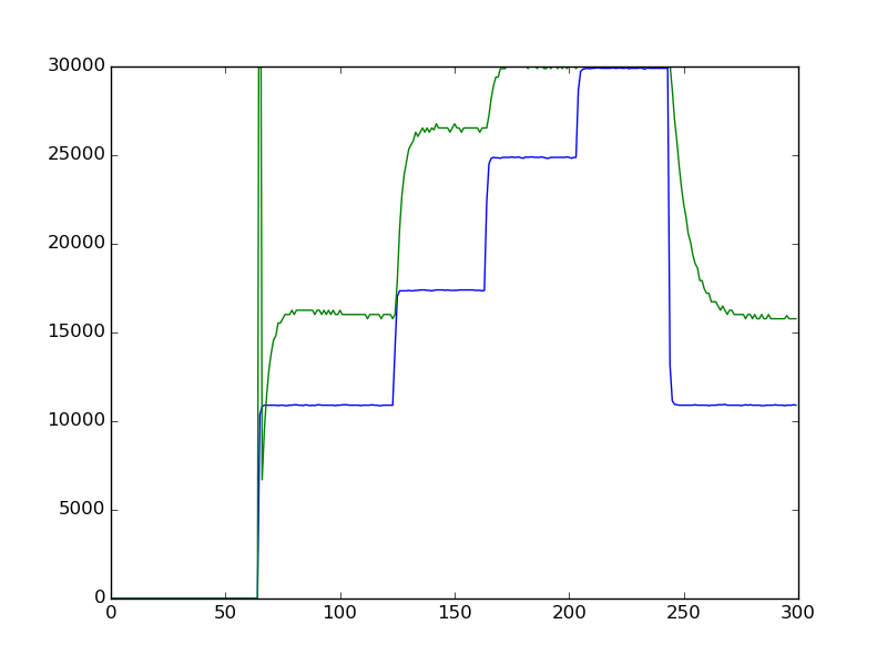
The blue line is the desired speed, and green is measured RPM. Time is rather confusingly done in samples which are 4 per second, so 40 samples is 10secs.
First up is the RPM change with no PID. I didn't expect the two to match up, as there is no feedback. But it's interesting to see the response time.
![]()
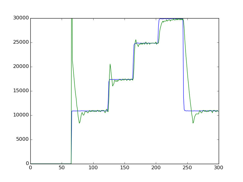
And here's with PID:
![]()
Where you can see the overshoot. I chose a fast response, which means that some overshoot will happen.
Now here's with a load applied. The load test was as followed: I put a broken bit in upside down, so there was a smooth steel rod spinning in the router. Then I put a lever on the bed. It was attached 40mm away from the router bit, and then 130mm from the pivot I hung a 115g weight. These numbers are arbitrary, I just had them to hand. The important thing is to be able to reproduce the test at a later date.
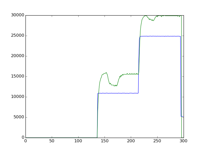
Again, first is without PID:
![]()
You can clearly see where the load was applied, and the change in RPM. Especially when at lower speeds, the load makes a bigger difference - which is why without the closed loop control I can't do slow RPM machining.
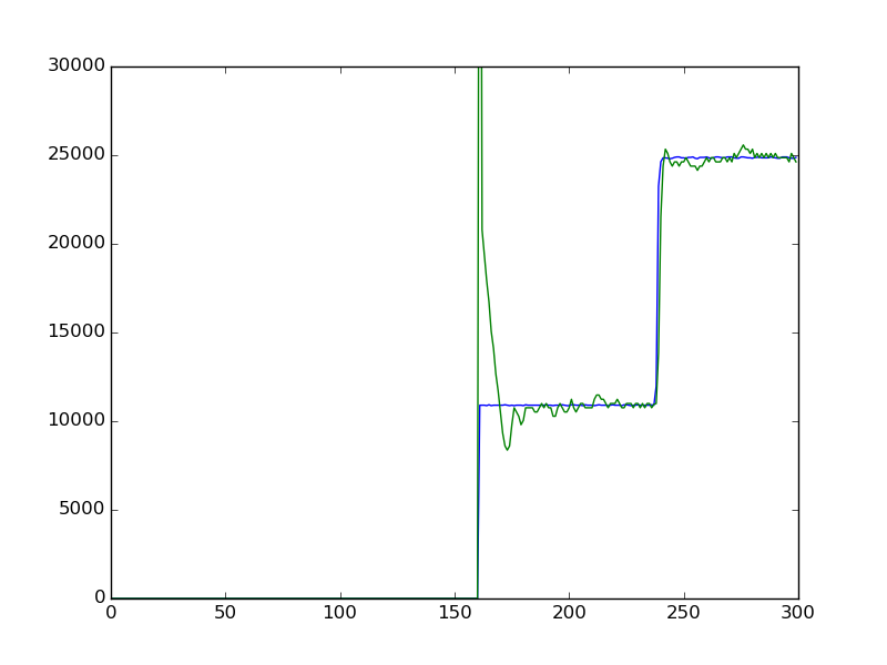
Now here's with PID:
![]()
It's difficult to even see where the load was applied. But you can see where it was removed because of the slight overshoot.
So a success! The last thing I want to do is try doing some machining at low RPMs with aluminium and low melting point plastics.
-
noise problem fixed
10/01/2014 at 10:46 • 0 commentsafter some suggestions from bristol hackspace mailing list, I traced the noise from the sensors on the router table (end stops). The opto sensor was put down the same cable, so the noise was transferred to its signal too. I separated the opto out onto its own shielded cable and the noise signal fell to about 600mV peak to peak. This fixed the RPM reading and now the whole system is working!
-
PSU noise problem
09/26/2014 at 15:10 • 0 commentsI got to the point of tuning the PID loop and found the RPM counter had stopped working - the RPMS went up as the motor slowed down!
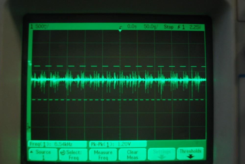
I checked the signal (while rotor was still) on the scope:
![]()
And found a lot of noise. So as the white band passes by the opto, not one count is recorded, but many. And the slower the rotor, the more the noise affects the count.
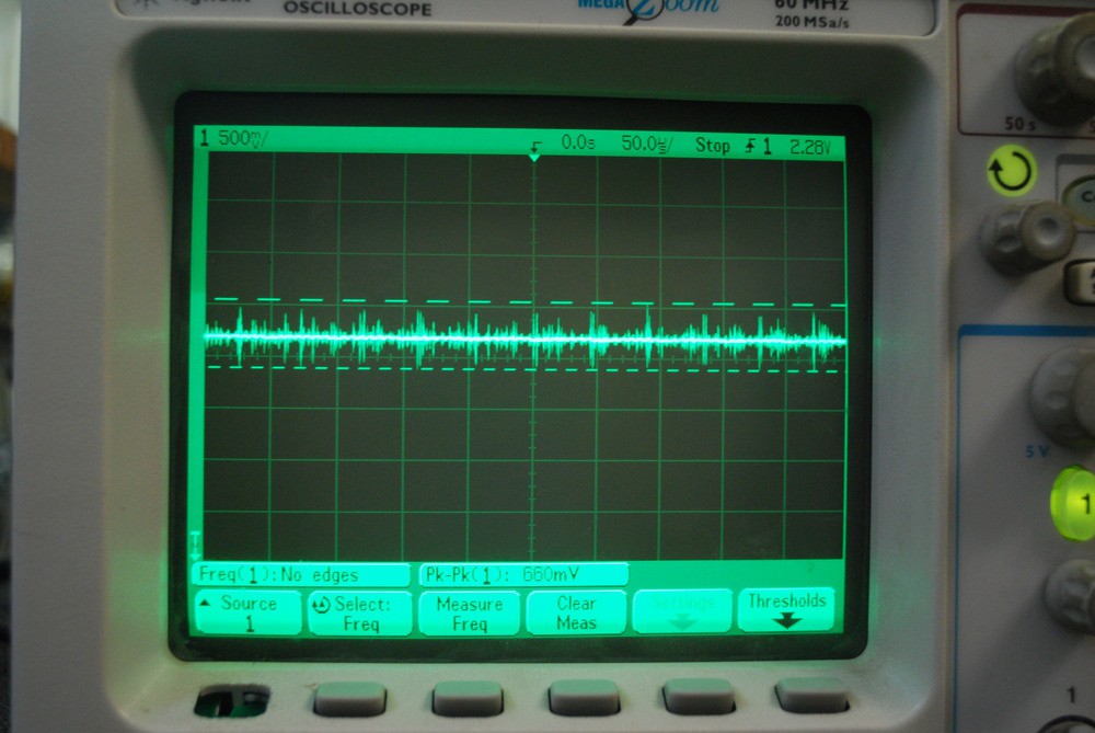
Tracing this back I checked the Arduino +5v supply:
![]()
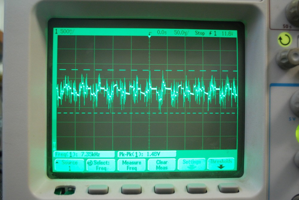
And then the 15v motor PSU:
![]()
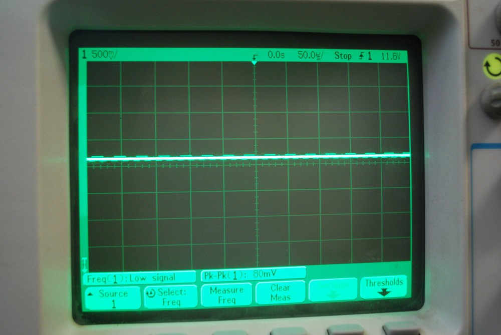
Finally, I checked the 15v motor PSU with the steppers disconnected:
![]()
With either the motor PSU disconnected or the PSU on but steppers disconnected, the RPM counter works.
The stepper driver boards have 2 supplies, one for logic and the other for motor. The motor control signals are all opto isolated. I measured for continuity between the 2 grounds (logic and motor) and they are not connected.
I can understand why there is a lot of switching noise on the PSU when the motors are on, but I can't understand why the noise would make it into the other PSU when they are isolated. I've tried a few different sizes of caps on the 15v motor PSU but they hardly help at all.
Can anyone help?
-
Linux CNC
08/03/2014 at 09:43 • 0 commentsThe final part of the project is to hook up the controller to my CNC control software, Linux CNC. Linux CNC has some good examples of how to do this over here.
I'd already done a bit of research on this so I knew the way it would work would be PWM. To make it easier to interface, I'd included space on the PCB for a simple RC low pass filter. I couldn't find any info on how fast the PWM signal is from Linux CNC (and I didn't remember to measure it). I just used a 10uF cap and a 10k resistor and that worked fine. The output from the parallel port is 5v, and I got from 0 to 1000 (out of 1024) on the Arduino analogRead() function.
If you build this and you're not using the filter, you'll need to put a wire link over the resistor or you'll get no signal.
I felt a bit unsafe about just using a speed signal to control the spindle, so I have a run pin and a speed pin. The code I used in the Linux CNC .hal file is here on lines 11 to 19.
I found out also that someone has used Linux CNC to do the PID itself! Which I didn't know was possible. I don't feel the effort was wasted though, as I'd still need to do the loop tuning, and the phase control TRIAC stuff.
-
PID
08/03/2014 at 09:33 • 0 commentsSo finally, the PID part. I have used PID before, on a home made servo (just for fun), and a dump load for a wind turbine power controller. I've never really felt like I got to grips with it though, so that's one reason why I decided to do this project.
I used the PID library which has some decent info on it, and I also read up on PID over on this PID for dummies page. It's really a very simple algorithm. We subtract the current RPM from the target RPM, and this is the error. The error is then multiplied by 3 different terms, P (proportional), I (integrated), D (derivative). The results are summed and this is used as the output to the motor speed control.
Take a look at the PID::Compute function in the PID library. You can see the proportional part is just the P term multipled by the error. The I term is the accumulated error (integrated), and the D term is the difference between this input and the input last time. The results are summed together and returned (they are also sanity checked to avoid going too fast or slow).
I plugged in the variables, had a guess at the PID values and let it rip! The first few attempts were wild oscillations, but after a while I got some values that seemed to work OK. P = 0.01, I = 0.001 and D=0.
The router spindle finds the target within a few seconds, and if I push against the spindle I can hear it trying to go faster. Then when I let go I hear a little spike in speed as the PID algorithm adjusts to the loss of the load.
I plan to do some more loop tuning later on, when I see how well it cuts.
-
RPM detection
08/03/2014 at 09:06 • 0 commentsNext up is determining how fast the spindle is spinning. I just followed Klass's method as I have exactly the same router - a kress fm 530. His instructions are here. He'd already done the hard work of finding a suitable sensor - the Vishay TCRT5000. I started off paining a thin white stripe on the plastic part of the spindle (sorry no photos as they all turned out pretty un clear). This didn't work, so I continued adding white paint and making the stripe wider and wider - I realised it didn't really matter how long the stripe was.
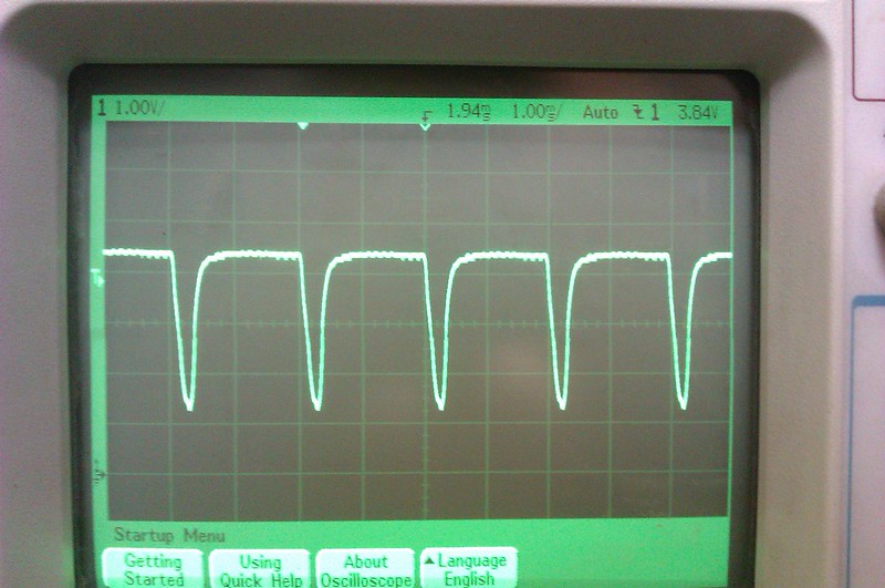
The resulting pulses looked like this, and worked out at the expected 30000RPM.
![]()
-
proportional control
08/02/2014 at 11:01 • 0 commentsThe next step was to test the phase control. Now I had functioning ZC detector and a working TRIAC I hooked up a pot on an analogue input and got hacking on the software.
This was pretty straight forward as I'd done some work with timers and PWM on Atmels before. It's a bit different if you've only done "Arduino" stuff before though, as it's necessary to twiddle some bits in some registers - which can look a bit scary.
Take a look at lines 55 to 61 on the arduino sketch. First we clear all the control registers, so the timer goes to default settings. Then by putting values into TCCR2B we set a prescalar to slow the counter down 1024 times (I looked this up in the datasheet).
Finally I enable the overflow interrupt by writing a 1 to the correct slot in TIMSK2. Look at the interrupt handler called ISR(TIMER2_OVF_vect). This gets run everytime the timer overflows.
Now we have a setup where timer 2 will count up from 0 to 255 (as timer2 is a 8 bit counter). This will take 0.016 seconds, but if we start the counter at around 150 it will only take 0.01 seconds, or half a sine wave on the mains frequency of 50hz. So by varying the starting point of the counter between 0 and 150, I can generate a trigger for the TRIAC that will be set it to be turned on for longer or shorter times. I mapped the analogue input from the pot to the range of 0 to 150 on the timer's register.
In hindsight, I should have used timer2 for the rpm counting and timer1 for the triac control, as I'm wasting
The next step is to sync the timer to the mains frequency, which is what the zero crosser circuit does. I made an interrupt handler called ZC_INT(), which just turns off the TRIAC and sets the timer2 count register to our desired starting point.
This nearly all worked first time, but there were a couple of issues that stopped it working perfectly.
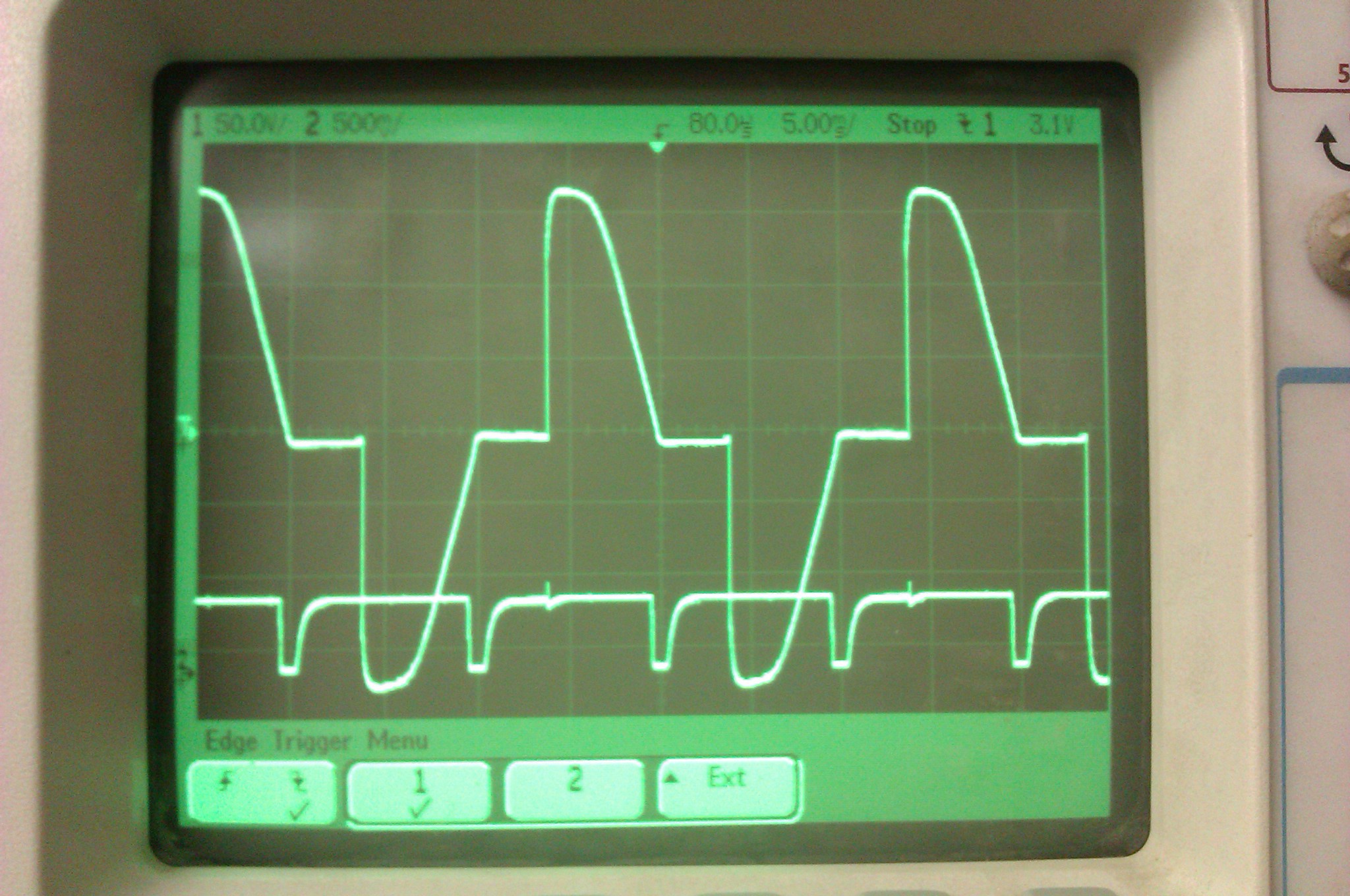
- I was detecting a rising edge on the ZC interrupt, which happens just after the zero cross. This stopped the TRIAC from turning off cleanly at some values.
- There was some noise when the TRIAC turned on, on the ZC interrupt (still slightly visible on the scope trace below), which was causing double triggering. I fixed this with a low value capacitor between ground and the signal.
![]()
-
zero cross problems
08/02/2014 at 10:38 • 0 commentsI was expecting to just steam roller the triac, zero cross and opto spindle detector and get on to the juicy PID. But the zero cross circuit took at least 4 hours of debugging to understand and get working. I had just copied this circuit, which has a great description of how it works too. I didn't bother to understand it, just put it in my schematic and had the pcb made.
Things seemed ok (no fire or smoke), but I didn't get any pulses out of the opto isolator. I was a bit hesitant to use the scope on mains (240VAC in the UK) but I got over that and soon was checking the wave forms. In fact, after the first 2 large resistors, the voltage is only about 16VAC.
I still couldn't understand why it wasn't working so I downloaded a (terrible) simulator and modelled the circuit. The thing I was missing was that the diode under the capacitor let's us compare "0v" with the incoming sine wave of the mains. I'm putting 0v in quotes because with AC we have to pick some voltage we're calling 0v. Then the transistor should switch on when the voltage on the diode becomes more negative than the voltage stored in the capacitor. I've got some photos of the scope during the investigation on the schematics github.
I could see this happening on the scope, but the transistor wasn't switching. The first circuit board I ever made didn't work because the footprint of the NPN transistor I was using was different to the one I'd used in the pcb program (Eagle). On a hunch I tried a different transistor and I got some results!
Still not great though, the wave form wasn't square at all, and trying to use it on an interrupt pin on the arduino wasn't going to work. I went back to the schematic, and also re-read the info on the ZC page (linked above). Although I'd put a footprint for the pull up resistor on the output of the opto isolator, I hadn't placed it - instead using an internal pullup inside the Atmel chip on the arduino. It turned out this isn't a pull up resistor, it sets the current through the opto transistor inside the opto isolator! So having a 20k odd resistor wasn't allowing enough current to saturate the transistor. It was behaving as an amp, not a switch. Well, kind of in between.
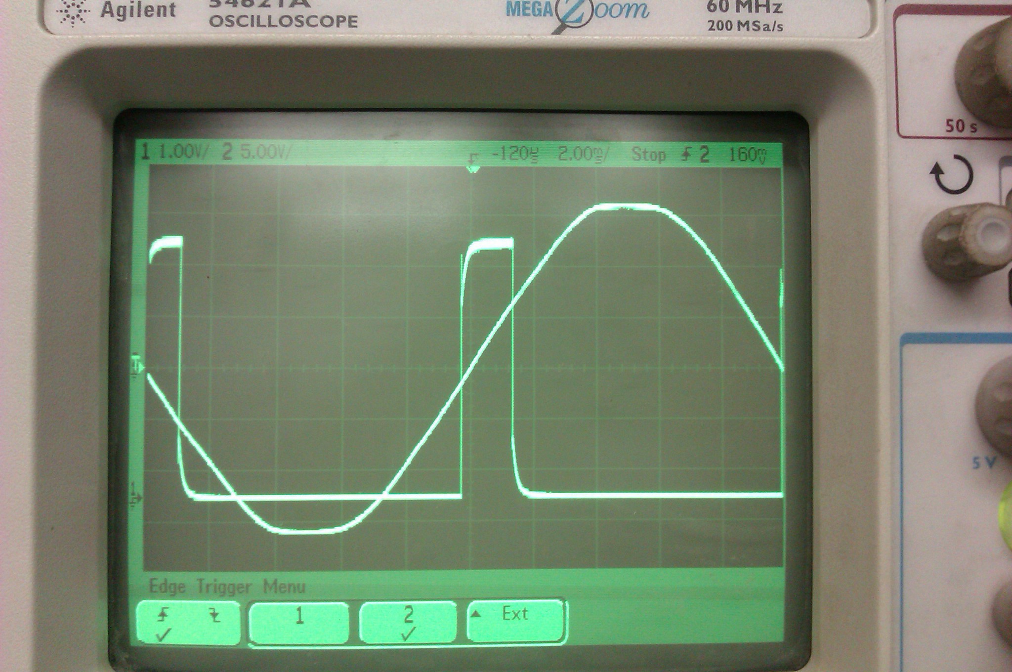
Placing the resistor, and setting it to 5k (as in the original schematic) solved this, giving me clean, square, fast pulse that started just before and ended just after each ZC. Perfect!
![]()
-
triac success
08/02/2014 at 10:24 • 0 commentsThe triac stuff worked fine and I could easily control a filament lamp. I checked that I could control the spindle too, and even with no heatsink the TRIAC didn't get too hot. Next up, the zero cross detector.
-
Project start
08/02/2014 at 10:23 • 0 commentsIt took a while to commit to this project, because I knew about the super pid and I don't want to waste my time on stuff that others have already done unless I can learn something significant. In the end I went for it because I'd seen Mic and Klass's work and thought I could duplicate that fairly easily, then focus on the closed loop feedback, which is something that I've wanted to understand for a while.
I took the schematics from the 2 projects, remixed it a little and started working on a PCB. The things I paid special attention to was making sure I used the right pins for TRIAC trigger and the RPM counter. As this work will mostly be done with timers and interrupts, and they have special, related pins that can't be changed.
The arduino uses timer0 for various delay functions. So I used timer1 for the rpm counting, and timer2 for the phase control. When timer 2 overflows, I can toggle an external pin that will control the triac. This leaves the main loop for controlling a display and running the PID algorithm.
Arduino AC motor PID
An arduino shield that lets you control an AC motor with closed loop feedback.