0%
0%
 SUF
SUFBecome a Hackaday.io member
Already have an account? Log in.
Just one more thing
To make the experience fit your profile, pick a username and tell us what interests you.
Pick an awesome username
hackaday.io/
Your profile's URL: hackaday.io/username. Max 25 alphanumeric characters.
Pick a few interests
Projects that share your interests
People that share your interests


 CiferTech
 Carbon
 Ben Holmes
 Nicolas Schurando
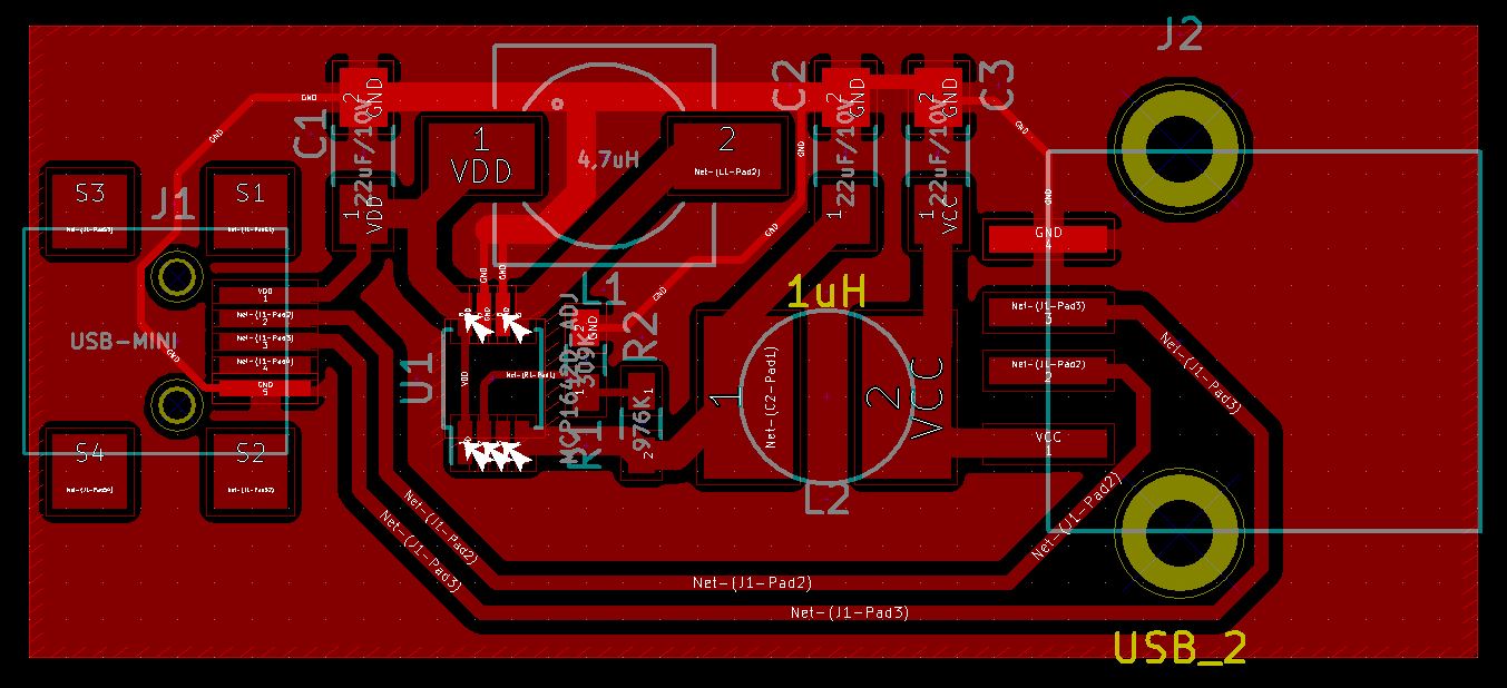
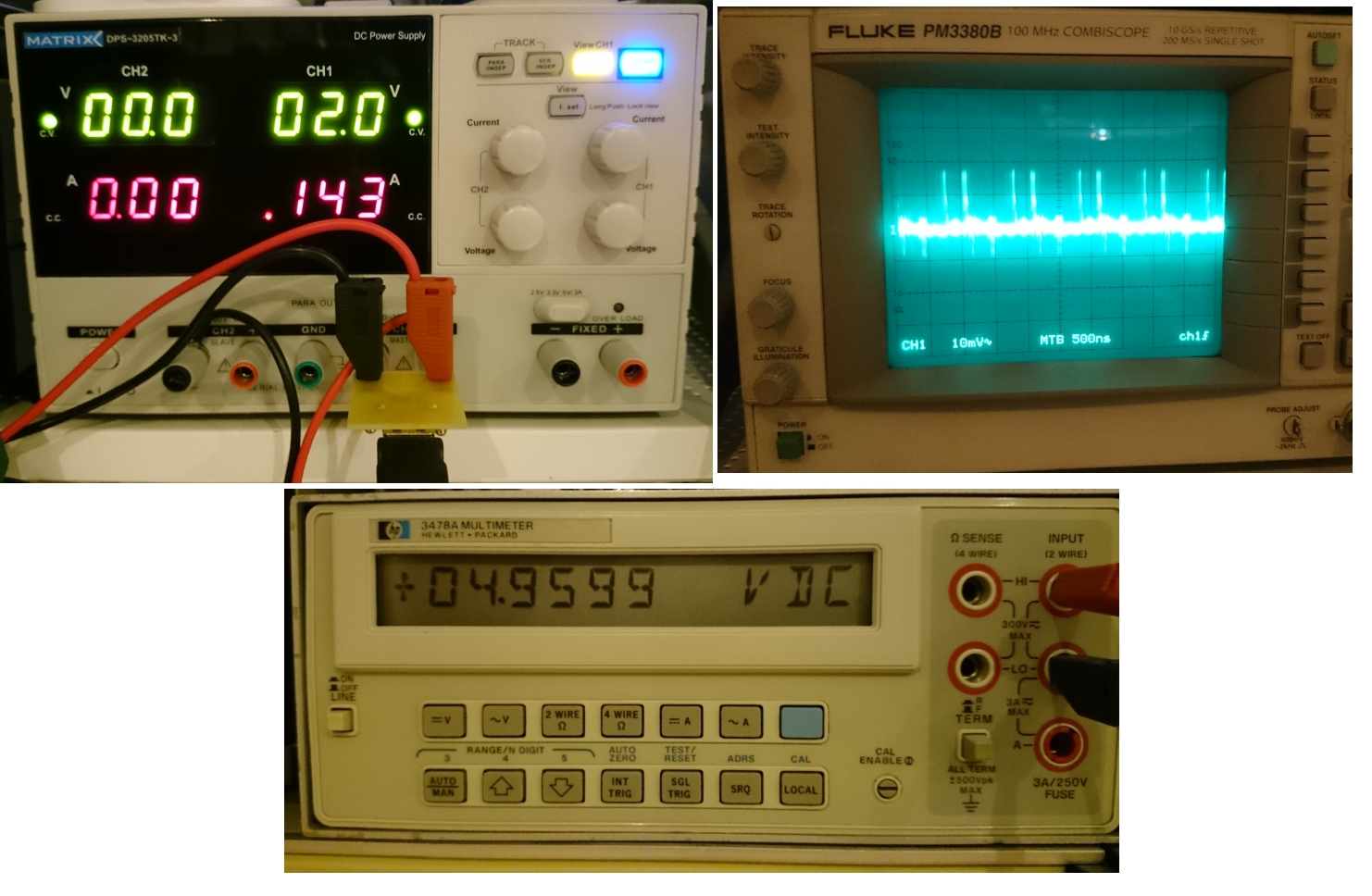
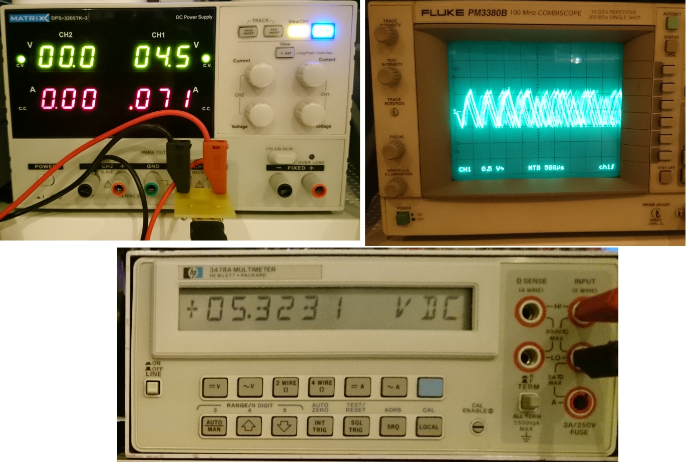
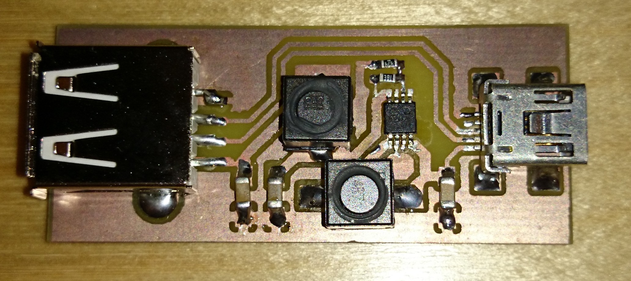
Interesting project. How much noise does the MCP1642 output have? I tend to prefer linear regulators when precise / clean voltage sources are required, but I have not used that one before.
Cheers