SUF
SUF-
Faliure no 2.
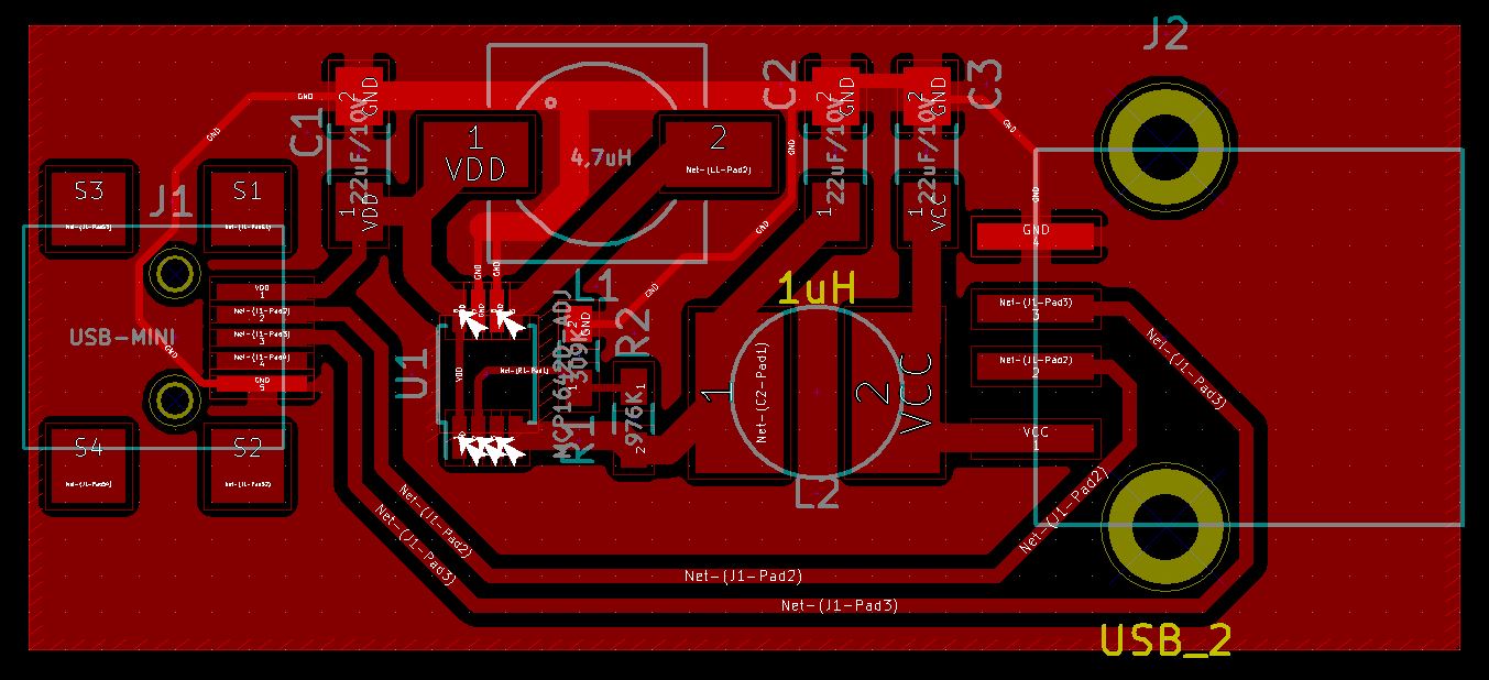
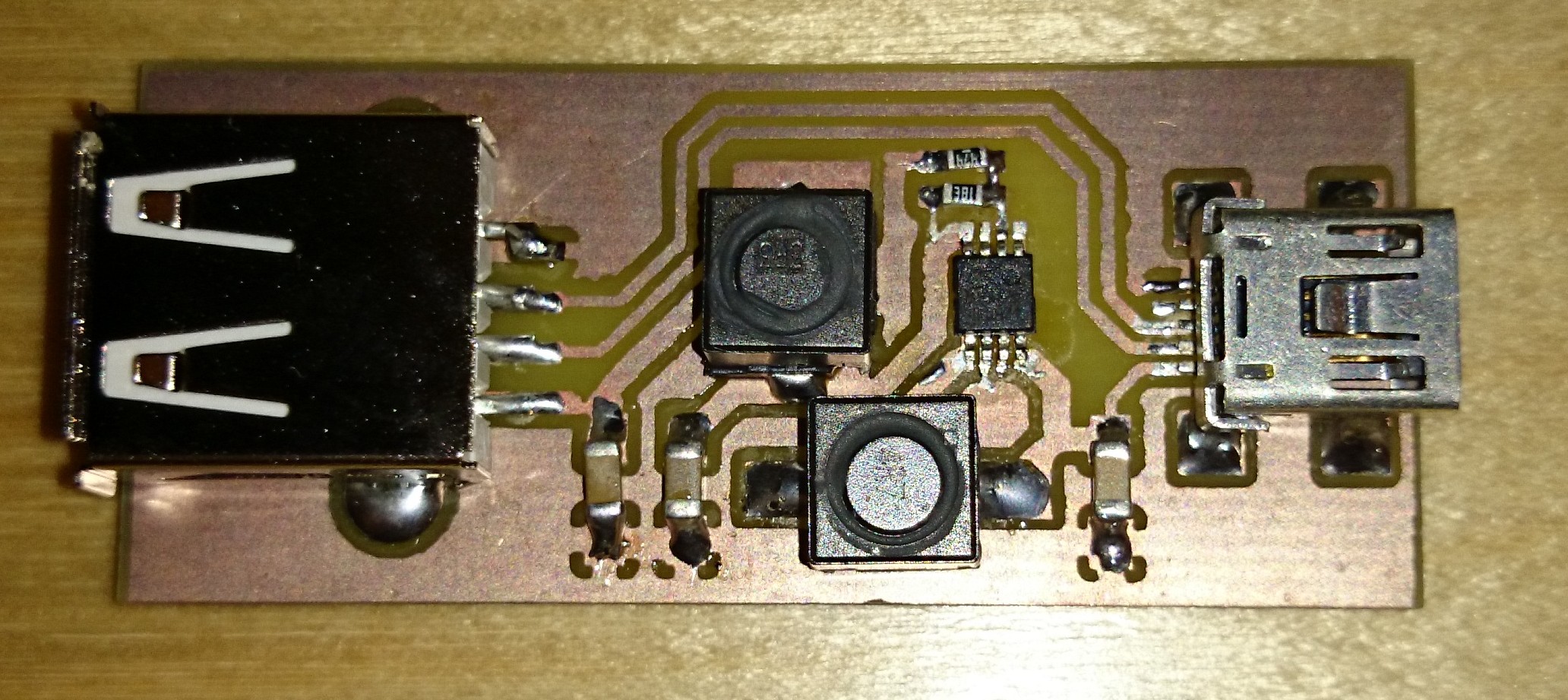
06/30/2015 at 13:58 • 11 commentsCreated a second board, now with the corrected USB connector pinout:

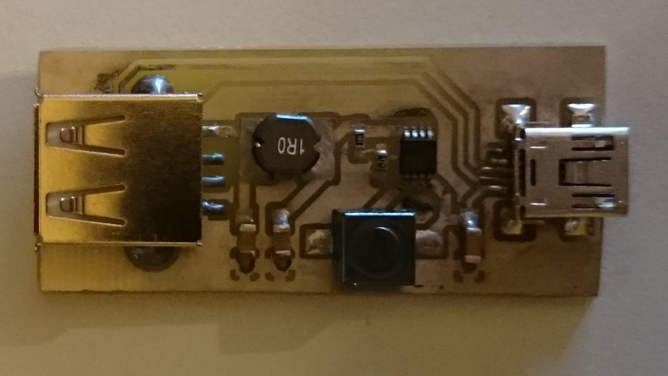
And I built it:
The problems started here.
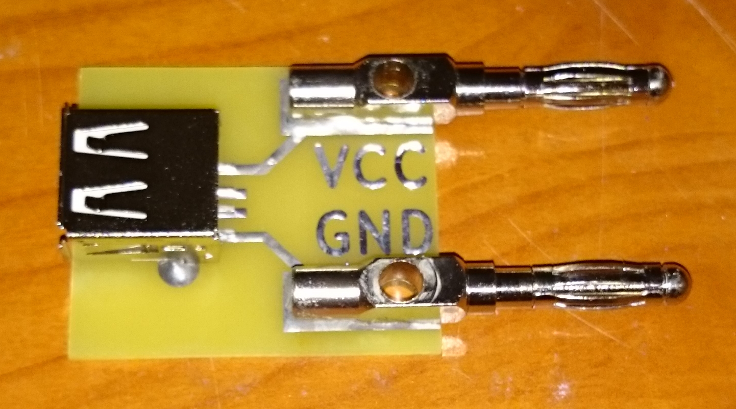
The first thing, I wanted to test it. To test it it is not enough to connect it to some random USB source. I wanted a variable source.
I've a lab supply, but it has no USB out. As I didn't wanted to cut any USB cables, I designed and built this small "tool":
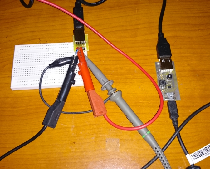
After this the testing went to a complete disaster.
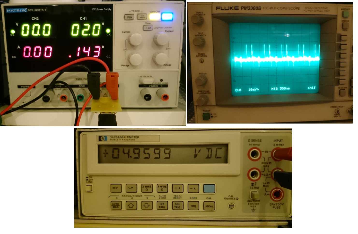
1. It was working from ~2V to 4.3V correctly, but when I went above 4.3V the output voltage just went above 5V. I was thinking this can be the result of miss of the minimal load, what usually required. So I setup the circuit with some (~50mA) load:
Testing..
At 2.0V:
Looks good
At 4.3V:
Still looks good
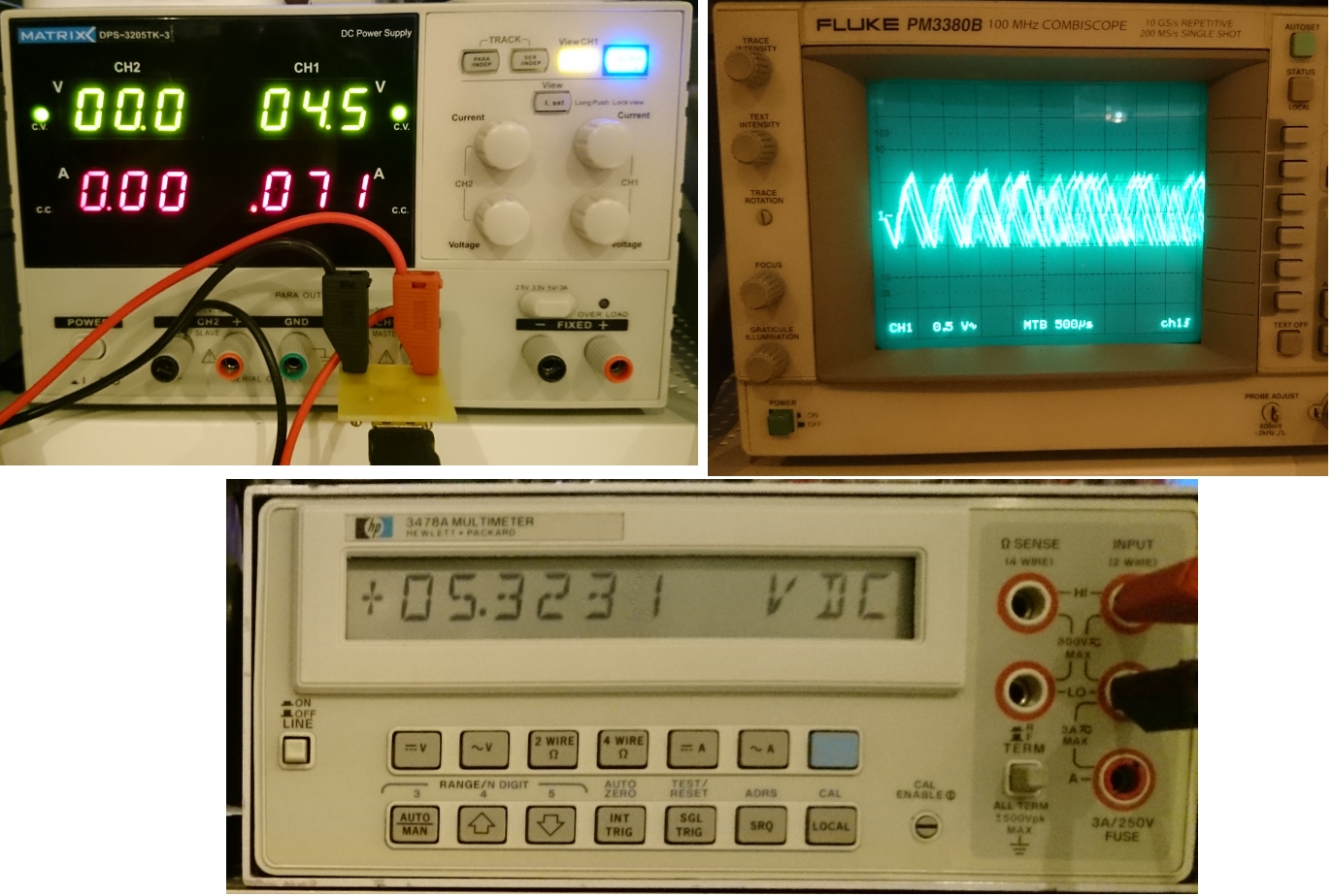
At 4.4V:
Not so good anymore. :-(
In addition, if I change the voltage, sometimes the whole circuit gets unstable. So the result clearly useless.
I've possible explanations to the things above:
- I've a crap layout - I'll try to enhance it in the next version
- I've some sort circuit(-is) things in my build. I can admit that using solid groundplane around the surface mount inductors without insulating solder mask wasn't my best idea
- The boost regulator is unable to handle the >4.3V in 5V out situation even if the datasheet just said Vout>Vin as a requirement
Here are the possible solution for the next try:
- Create a new board, with different layout and definitely with a cutout in the groundplane around the inductors
- Use the pass trough capability of the chip (this will require some kind of external comparator)
- Use a different (buck-boost or SEPIC) circuit - I may try the LM2621 what I ordered already for one of my other projects
- Keep the current boost converter (rising the output voltage to - let say - 6 volts) and use it as a pre-regulator for an LDO. As It suggested by The Big One.
-
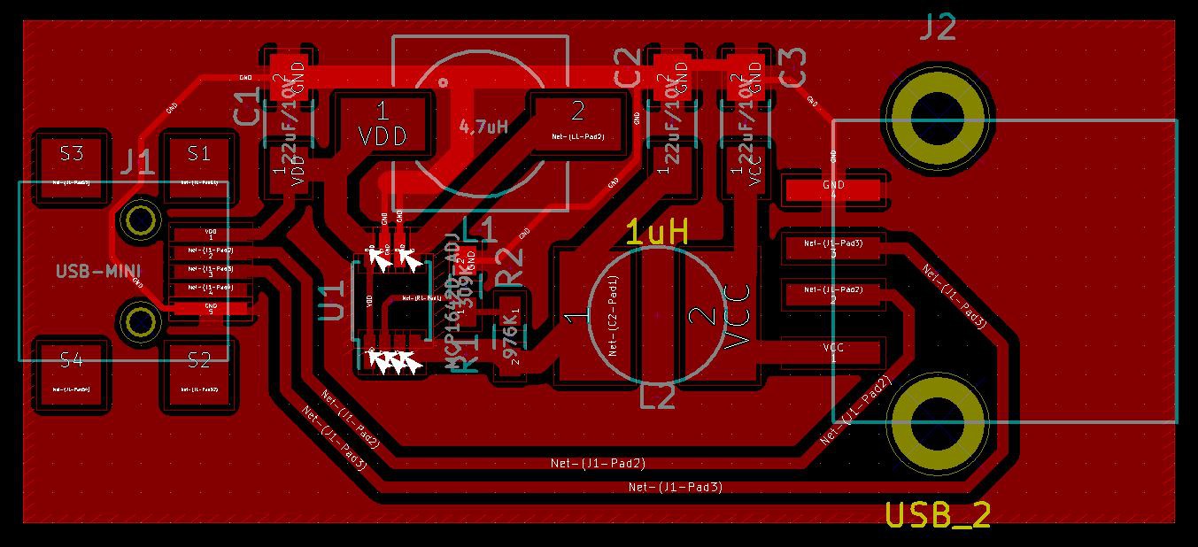
Updated Design
06/06/2015 at 03:18 • 0 commentsFinally I decided to create a new board for the project. The design is here:
I plan to create the board over the weekend
-
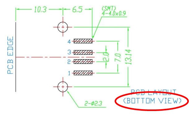
Fail
06/05/2015 at 03:54 • 2 commentsMy mistake, component manufacturers insanity (my opinion).
I was not even dream of, that somebody put a PCB layout of a surface mount component from bottom view. When I created the Kicad module from the datasheet, I didn't checked this "BOTTOM VIEW" note on it. So the component was connected in the wrong direction.
So the regulator works, just the whole board useless.
PCB rediesign, rebuild will come.
-
Built
06/01/2015 at 20:44 • 0 commentsI just built the first version today. Unfortunately some of the components not really fitted in, so some tweaking/parts changing was necessary. With some load it not really looks working. I should check, what is the problem with it.
-
First Design
05/20/2015 at 03:30 • 0 commentsAs I was looking for a power solution for my Boostuino project the Microchip's MCP1642 boost regulator. Finally it was not suitable for that project, but I realized this could be a good candidate for the USB Booster:
it has much higher efficiency than the good old MC34063
available locally for reasonable price
low size/value external components needed due to the high switching frequency
So based on these factors I designed a circuit for it.
The circuit is available in its newly created gihub repo: https://github.com/sufzoli/suf-electronics-USB-booster