Close
0%
0%

OpenDerby

Opensource Timing system for a Pinewood Derby track

Similar projects worth following
An opensource derby timing system. Timing done with a Raspberry Pi and IR photo resistors and the results are presented through a web interface written in flask.

Timing is accomplish through hardware interrupts on the RPi. Starting gate is triggered by a switch on the start gate. Each lane's finish is triggered by an IR sensor at the finish line. Registration, Heat Generation, Pit coordination and Results display are all managed through a web interface. Heat results gathered by the RPi are stored in the database shared by the web interface.

  • 1 × Raspberry Pi timing hardware
  • 1 × Flask Python Microframework Framework for the web interface
  • 6 × IR photo resistors finishline sensors, 1 for each lane
  • 1 × Reed switch Start line trigger

  • We ran our derby April 23th, 2015!

    Dan Radez05/07/2015 at 19:32 0 comments

    We ran our derby April 23th, 2015!

    Lane 5 failed on me and the start lane needed debouncing in a bad way.

    I learned a lot from this race and will be making improvements to the setup. I hope to post some schematics for building the start and finish line at some point.

    Let me know if you would like some help getting a copy of this project off the ground. I'd love to see others using it and get your feedback to make it better.

View project log

  • 1
    Step 1

    I've started with a 6 lane version of something close to this: http://www.rahul.net/mcgrew/derby/track/

    Mostly the dimetions were used from this site. The actual construction was a bit different. I used 1/4" plywood as the base and cut up a 4x8' sheet of the same plywood I used for the base to make the lanes. Then I lined the edges of the base with 1x2" boards and constructed joints to attach the sections together.

    See the project photos to see how it turned out.

    TODO: Post some close up photos and more details on the build

  • 2
    Step 2

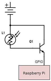
    Wire the RPi's GPIO to the start switch and finish line IR sensors. The start switch can be wired directly to the Pi's GPIO port. Each lane needs an IR photo resistor and NPN Transistor wired to the Pi's GPIO like this:

    I used RJ-45 jacks to connect the start line switch and photo resistors to a PCB. The transistors and a header for a ribbon cable to the Pi are on the PCB. See the project photo with the 2 RJ-45 jacks on it to see what it looks like.

    See the code to know which GPIO ports to wire the start and finish hardware into.

  • 3
    Step 3

    Run the Flask application from the code repository to setup the web interface and seed data. (TODO: add details)

    Then add categories and racers.

View all 6 instructions

Enjoy this project?

Share

Discussions

Dan Radez wrote 02/22/2017 at 16:27 point

Sry I haven't replied to your message, I've just come across the notification that was sent to me that you had commented. Did you build your track? You can visit the github link to get the scripts. Happy to help you get it working. Would love some help on documenting it.

  Are you sure? yes | no

Henrik Stagnell wrote 09/28/2016 at 15:36 point

hi there. I am qurious about your Project. Is there any way to get the scripts for it? I'm about to build A pinewoodderby track and searching for A suitable timing system to run with my raspberry pi.

  Are you sure? yes | no

Similar Projects

Does this project spark your interest?

Become a member to follow this project and never miss any updates