Josh
Josh-
Circuit Board Progress
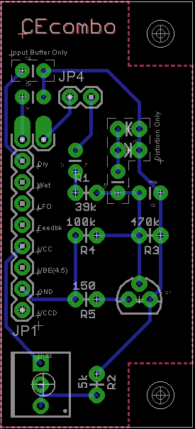
06/22/2015 at 17:39 • 0 commentsA quick update... after looking at how much work it would be to assemble even a small batch of perf-board prototypes, it seems like a better idea to go ahead and design some circuit boards and have them made at a board house. So the past few months in my spare time (which isn't much) I have been learning Eagle and attempting to design some boards. I have several designs, including the buffer and drive sections of the Pi and the TS buffer circuits that I used in the POC. After a few iterations of the Pi circuits, I realized that there are common enough features that I can design a single board to handle both the buffer and drive by either including or excluding components. This is great news, as it means I can get a batch of these and choose the function when the components are soldered on. I still have some things to add, such as the OS licensing marking and Project name, but here's the first rough schematic:
The holes on the right are for the mounting, stacking headers on the left, and JP4 is for the external input pot. The dashed line boxes are for the optional components that determine if the board is an input buffer (in which case it feeds the "Dry" bus channel through a cap) or a drive section (where diodes are added for clipping). The pot in the bottom right adjusts the Collector bias for controlling clipping or gain. If the pads look close together, I plan on mounting all of the resistors and diodes in a vertical configuration.![]()
I'll post another update when I get some more boards routed and make an order.
-
First Proof of Concept Circuits Complete!
04/08/2015 at 03:52 • 0 comments![]()
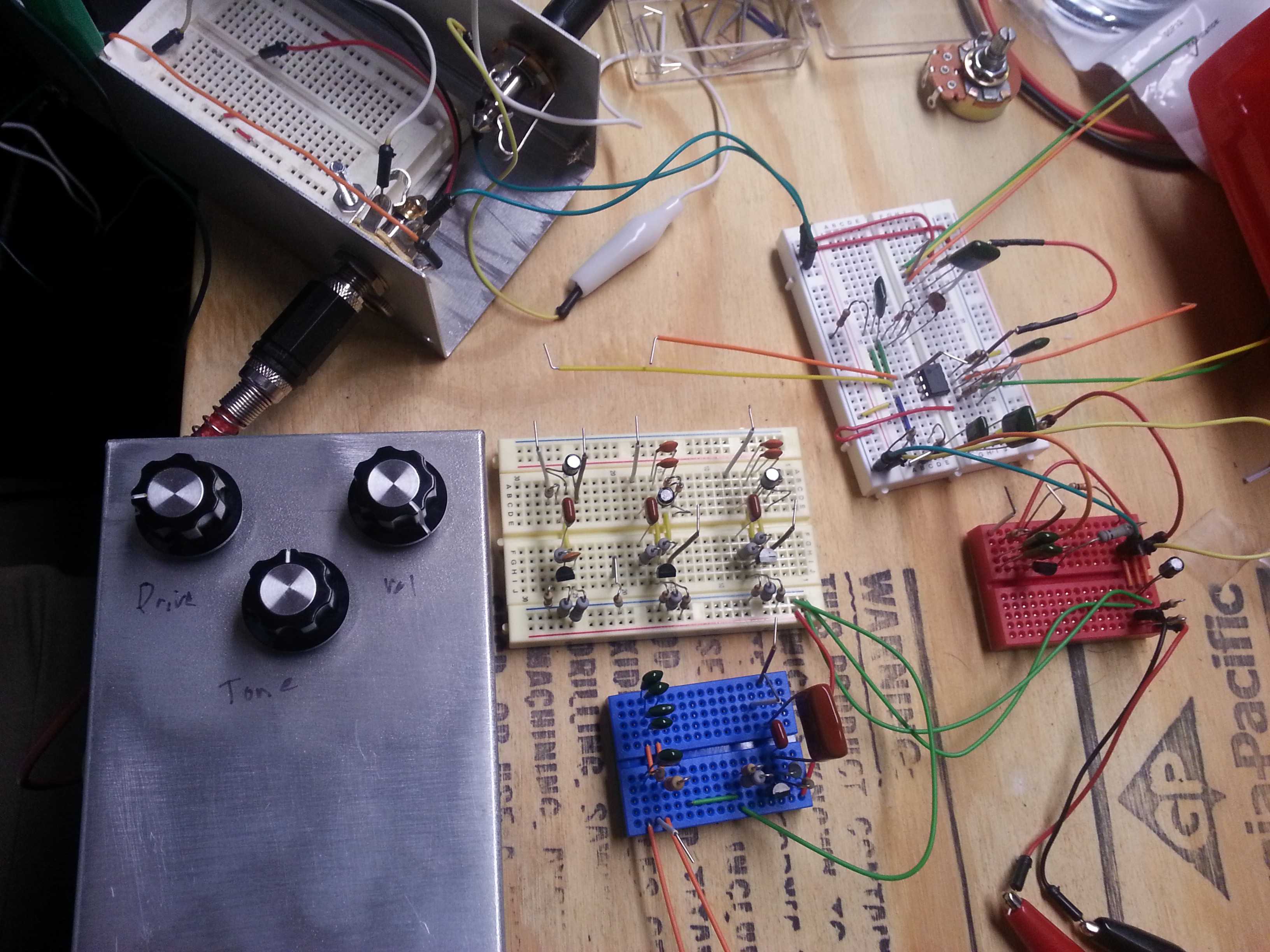
This is just a quick update to say that the first POC test has proven successful on breadboard! The videos have been added to the Prototype Status section of the project details. Not much to see, and I'm no pro guitar player either, but you can at least hear the results of the circuits!
There is a Tube Screamer clone and a Big Muff Pi clone made using modular circuits. I run the TS by itself, then the Pi by itself, then I proceed to hook the TS drive to the Pi Tone, followed by the Pi drive through the TS tone. Finally, I stack the TS buffer and drive in front of the Pi drive, skipping the Pi's input buffer, and out through the Pi's tone and output buffer.
In the next post I will show the circuits used and go into some more detail, but for now, enjoy the videos!
Electronic Proof of Concept videos:
-
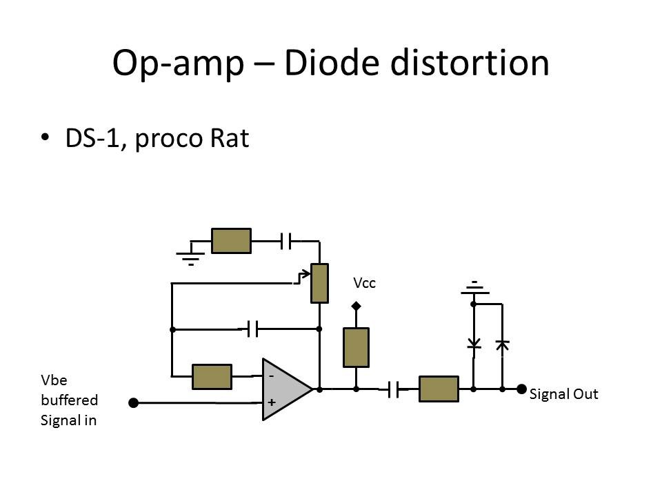
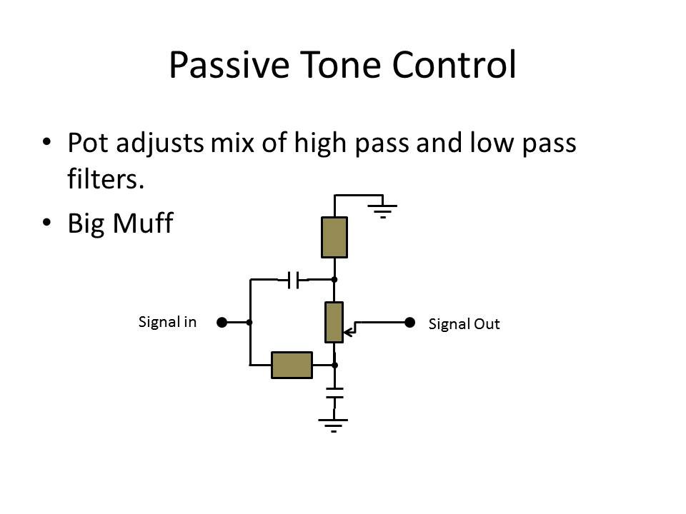
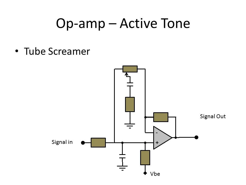
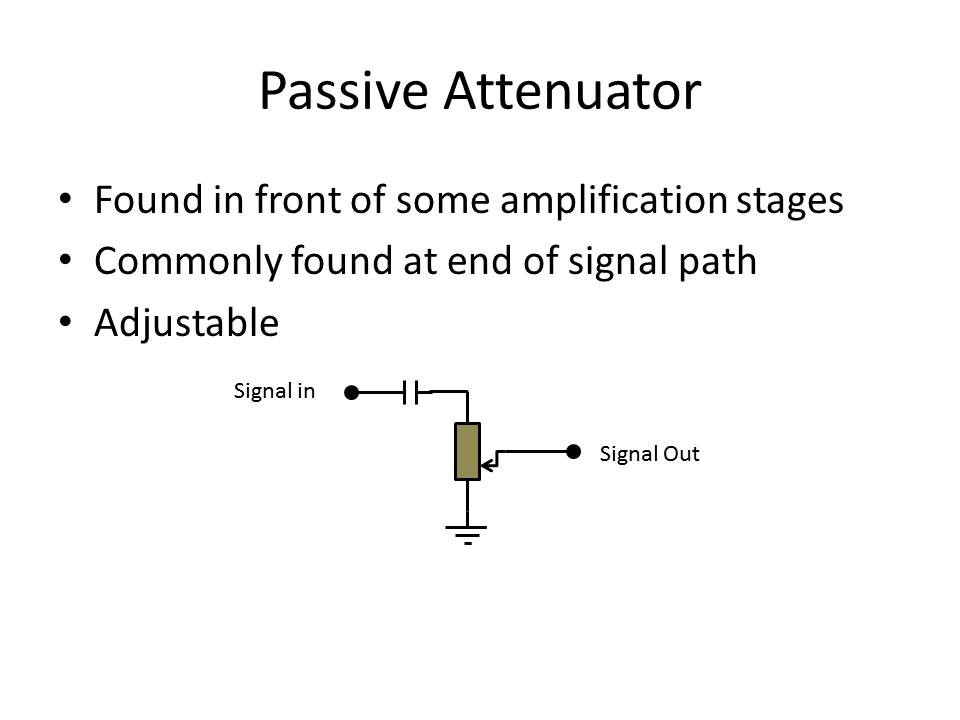
Circuit Similarity
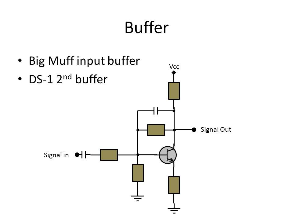
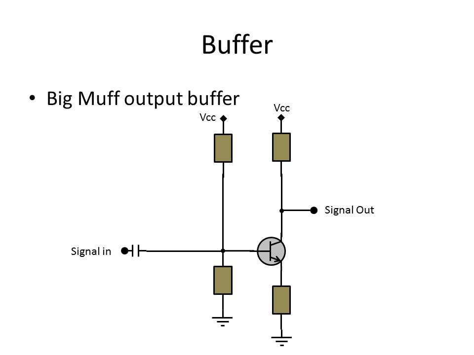
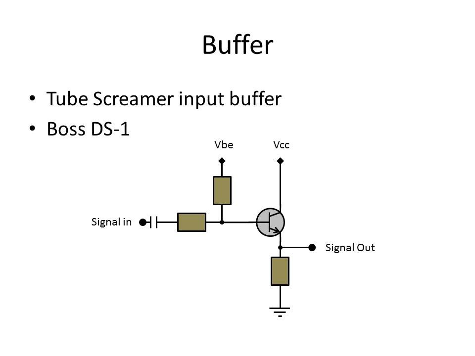
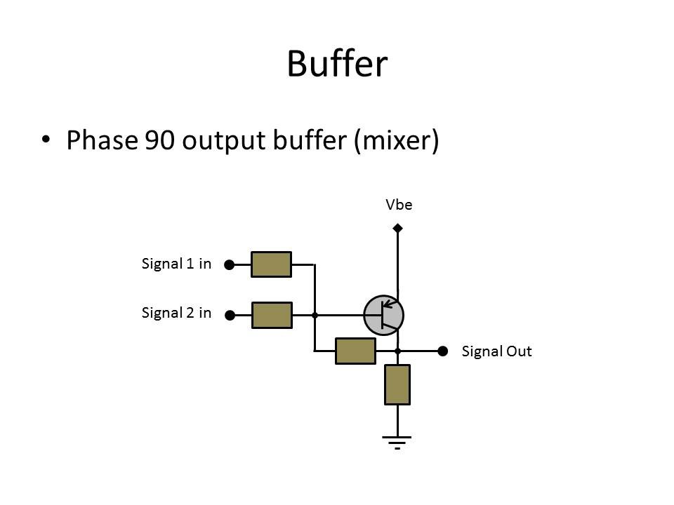
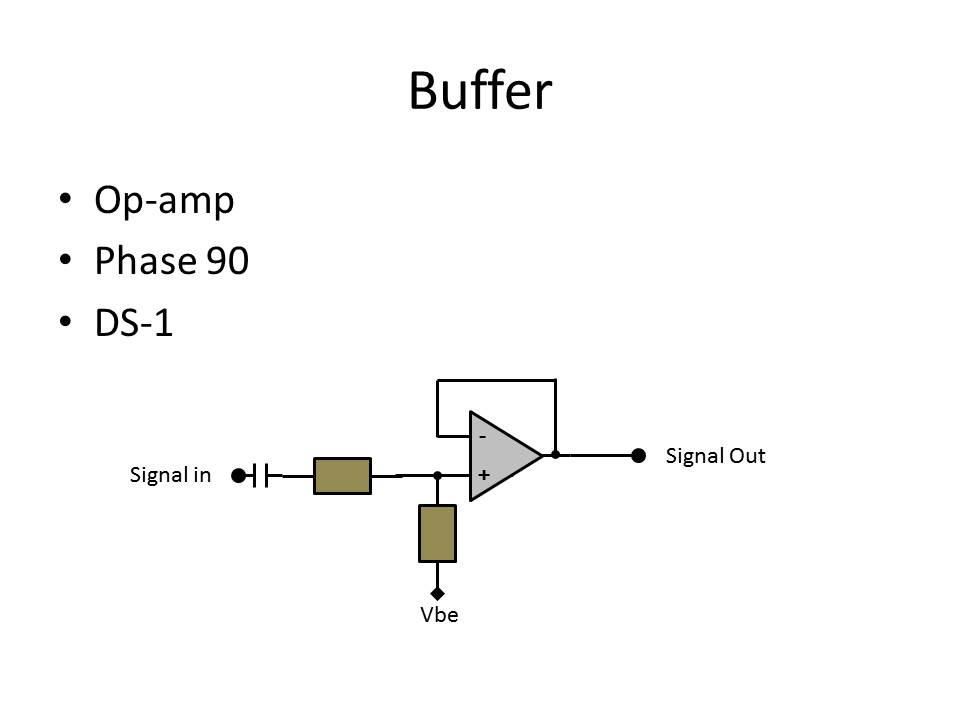
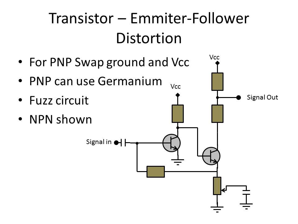
03/19/2015 at 01:10 • 0 commentsI've had a brief chance to get back on this project, and I have a number of module circuits diagramed out. In the following diagrams, I have done as best I can to lay them out in such a way to spot similarities. With a bit more study, a universal breadboard design could probably be built for each similar circuit. Take for example the first Buffer, and the first Transistor-diode distortion. The only difference is the additional diode pair and cap. Many other similarities can be seen, lending to the idea that a universal circuit card could be made. Check out all of the module circuits after the break.
![]()
![]()
![]()
![]()
![]()
![]()
![]()
![]()
![]()
![]()
![]()
![]()
![]()
![]()
![]()
![]()
![]()
-
Hiatus
11/11/2014 at 15:16 • 0 commentsAfter my long shot to make it to the semi-finalist round of the Hackaday prize did not pan out, I had to put this project on the back burner in order to focus on some more pressing life issues. In the mean time, however, I did manage to begin breaking down some common analog circuits to modularize them. The following is a list of potential module types:
- Buffers (these can be input and output)
- Transistor based distortion
- Op-amp based distortion
- Passive tone control
- Active tone control
- Passive attenuators
- Active attenuators
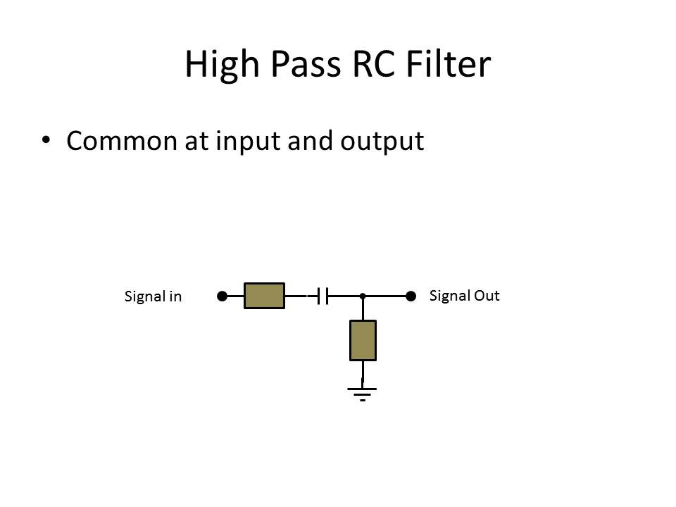
- Passive filters
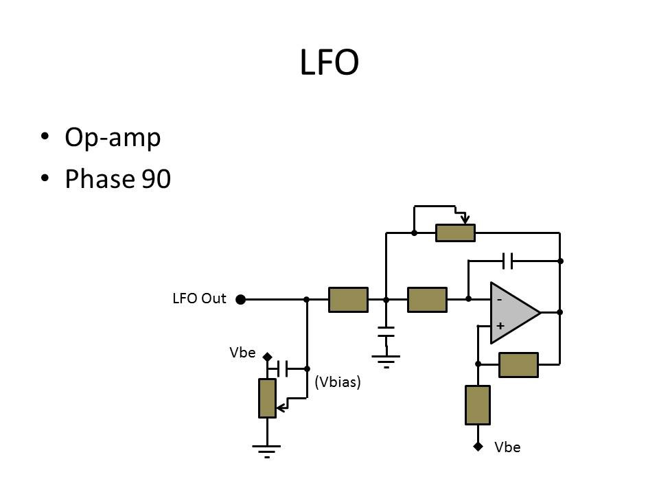
- LFO
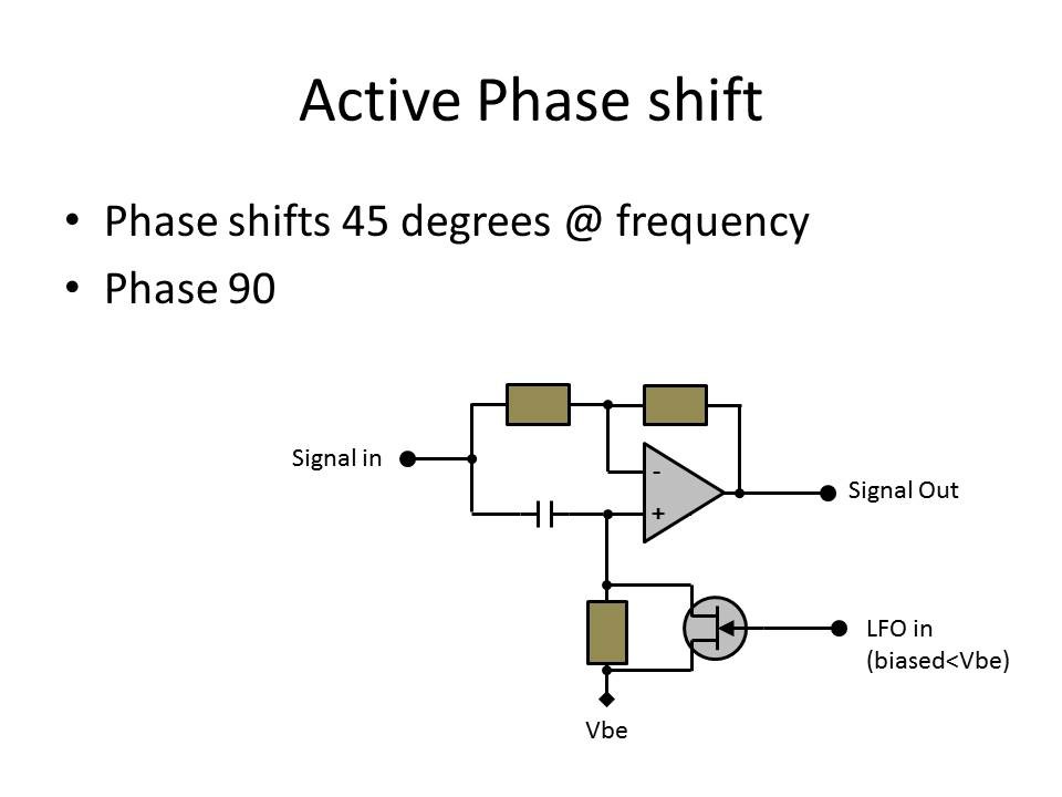
- Active phase shift
- Active flip-flop switch
Each one of these types form basic building blocks, which can be assembled in a linear fashion to create a complete pedal.
As an example, to build a TS-808 you would assemble the following:
Input → Buffer → Op-amp based distortion → Active tone control → Passive attenuator → Flip flop switch → Buffer → Output.Another example; to build a Big Muff, you would assemble the following:
Input → Buffer → Passive attenuator → Transistor based distortion → Transistor based distortion → Passive tone control → Buffer → Passive attenuator → Output.It's easy to see then that hybrids of these pedals could be attempted by swapping out transistor distortion for op-amp distortion, or even stacking entire sections of pedals together.
How about an 808-Muff?
Input → Buffer → Op-amp based distortion → Transistor based distortion → Passive tone control → Buffer → Passive attenuator → Output.Or how about using LFO and an active attenuator to create distortion vibretto?
Vibrostortion:
LFO → active attenuator ↘
Input → Buffer → Op-amp based distortion → Active tone control → Passive attenuator → Buffer → OutputIn future posts, I'll be sharing the generalized layouts of the specific module types.
-
How Many Buses?
08/19/2014 at 22:18 • 0 commentsThe Bus Problem
Edited 4/21/15 - Rearranged the bus, mirroring the 4 power channels to put Vccd on the end. The prototype boards will not have this channel and can use 8 pin headers this way.
Now that the bus structure is defined to use stacking headers, how many bus channels are really needed? To answer this is a combination of requirements and flexibility. I have never designed a bus before, and just as a head's up... I'm not even sure if I'm using the correct terminology!
Power
The obvious required bus channels are Power. The majority of guitar pedals use 9V input from either a battery or external power supply. This is halved to get a psudo ground with +/- 4.5V. Since the majority of the topology of these circuits involves transistors, these are 3 of the required bus channels: Vcc (collector - ground), Vbe (base - emitter/ground), Vee (Ground). Next is support for power for a digital circuit requiring a separate regulated supply, Vccd. Since the power consumption for the modules is usually low, a single ground will suffice. Current draw will become the first derived requirement. This brings the total required buses to 4.
Audio Signal
For the signal buses, one will be the main audio signal bus, and presents a dilemma - it is serial for any module that processes signal, so a method to maintain the vertical stacking shield capability must be implemented. The solution I have found is to place a male pin on the top side of the board, adjacent to the required female plug, and insert a female pin jumper with the blank in line with the stacking header. An alternate solution is to use a stacking header spaced off of the board enough to place an offset bend in the signal pin to move it to an adjacent hole, and place a normal male header pin below it, insulated. Because of the two methods, the signal bus will be placed at the edge of the buses. At this moment, I can find no reason to have more than one main audio signal bus of this nature. This brings the total buses to 5.
Feedback, Wet Mixing, Switching, and Expansion
In audio circuitry, there is sometimes a need for a feedback line for reasons such as distortion control and stability. In my searching, I have not yet encountered a circuit with more than one feedback line. On the other hand, some effects require the dry signal to pass through and mix in with the final processed signal, and ome, such as the Phase pedals, require an LFO. Even implementing a bypass switch that occurs after a buffered input, and before a buffered output poses a requirement for a dry signal. And then there is the need for a communication path for any digital circuitry. Tallying these needs without going overboard, we need 4 more buses.
But what about future expansion? Should I add more than 4 more buses for parallel signals? Where is the trade off for unknowns and board real estate? A better method would be to make these "addressable". The 4 parallel signal buses will be called "General Purpose" buses, with the recommendation that they are used in this order: Feedback, LFO, Wet, Dry. This brings the total number of buses to 9.
Implementation
The bus channels are:
- Vccd (regulated for the appropriate voltage)
- Vee Ground
- Vbe (4.5V)
- Vcc (9V)
- GP1 (Feedback)
- GP2 (LFO)
- GP3 (Wet)
- GP4 (Dry)
- Signal
Stacking headers come in various sizes, but common are 6, 8, and 10 pin. The 9 bus channels identified here can be implemented using either an 8 pin stacking header and use the jumper method for the signal on the 9th pin. The second method would be to use the offset pin method with the 10 pin stacking header.
Added 4/21/15: making the Vccd channel optional allowed an 8 pin stacking header to be used with the pin offset method on the prototypes.
-
The Wheels on the bus go round and round.
08/19/2014 at 18:13 • 0 commentsArt doesn't fit in a box.
During the development of the requirements, I kept a mental note of how I thought the design would look considering the current requirement set. I had originally envisioned something like a strictly defined chassis with a backplane that the module cards slide in to with the face plate and any controls on the card itself. This idea is great from a standards point of view, because everyone has the same "box" to fit in to. The downside is that it severely limits who can actually build one of these pedals. The average guitar player doesn't even know what a 3d printer is, so unless this chassis is available in every music store in america, it's a bad way to start. This also forces anyone who is out to create an artistic pedal to be limited to choices of paint.
Art can't be confined to a plate.
Freeing the design from the confines of a rack style chassis, my next thought was to flip the insides over, and have a backplane that mounts to the underside of the top of a box, and have the modules plug in from the bottom. This frees the top of the box to be any shape and size that the artist wants... except it can't be smaller than the backplane. But what if I just want a buffer? I don't want a giant pedal for one module. So how big does the backplane need to be? Four Modules? Eight? What about a backplane that is perforated and can snap apart? This is getting complicated...
Keep it simple, stupid.
Somewhere in all my thoughts on backplanes I realized that if someone has to do something more complicated than plug a new module in, it's to complicated for most of the target users. Then I remembered that there is a bus technology that has recently become wide spread, requires no backplane, and expands with every module added... the "shield"! Brilliant! Using the shield bus concept, I can stack my modules, and completely break the dependence of the enclosure shape and size on the internal electronics.
-
Who is the User?
08/19/2014 at 18:10 • 0 commentsBackground
I have been a Front of House sound engineer for several bands over the past 5 years. I dabble in playing guitar, but I'm by no means an expert. With all of the great digital pedal boards out there, most of the players still prefer stand-alone pedals. My interest in electronics got me to studying the internal circuits, and I realized that these "magic" boxes are really quite simple. So I built a few prototype pedals and they sounded great! Other people thought they sounded good too. The general comment from guitar players was: I wish I knew how to do that.
Here's to you, Mr Guitar Player
Who is the user? Every guitar player. In the simplest form, modifying this pedal should not pose any more complication than changing out a tube in a tube amplifier. Step one: open box. Step two: plug modules together. Step three: Plug in controls. Step four: close box. Step five: shred guitar. As easy as stacking Legos. Does your buddy's pedal sound better? Try out his magic module on your pedal! Just plug it in and play!
Here's to you, Mr DIY Guy
There's a second user out there... the true experimenter. The guy who tried his friend's tone control module and has to have it tonight. Well here's to you: go to radio shack right now and get everything you need for that tone control. Boom. The 'Shack may be dying, but it's still the only place you can go get parts this second to build something (in the USA, anyway). That may sound limiting considering the wide array of available online sources, but how "open" is a pedal that can't be built from parts you can buy down the street?
The User is YOU.
If your comfort level is "I can plug some stuff in" then you will enjoy the benefit of obtaining modules and assembling them to recreate that pedal you always wanted! Or you can throw caution to the wind and stick some fuzz in front of your tube overdrive module! Just being able to experiment with modules in different orders will provide an easy custom pedal that you can actually gig with.
But if your comfort level is "I'll make it myself!" then you can have all the confidence in the world that following the spec will ensure your scratch-built module will work in any other pedal.
Whatever your comfort level, a custom pedal is now within reach.
-
System Requirements Draft 1
08/18/2014 at 21:14 • 0 commentsUsing the list of pedals from the Survey, the system level requirements have been completed on a First Draft basis. There should be enough requirements now to define the majority of the system. The only requirements still lacking are the physical definition of the position of the bus and standoffs. These will have to be worked out in physical modeling.
Check out the current requirements here!
-
Artist Survey 1 - Results
08/11/2014 at 19:19 • 0 commentsSocial Fail.
Well, that survey produced an underwhelming 3 responses. To those who did respond- thank you! Your results were included in the new method below. The following pedals were listed from those 3 responses:
- Ibanez Tube Screamer
- Big Muff
- MXR Blue Box
- Danelectro Tuna Melt Tremolo
- EHX Double Muff
- Boss DD-3
New Method
This is not even close to enough data to begin feature categorization, so I am going to implement a secondary approach. The internet is full of articles on "The Top X Guitar Effects Pedals" or similar articles. I did a few searches for top 10 lists, best pedals, and different combinations in order to find as many articles as possible. For each article, I pulled out the named pedals and added them to a list. Each time a pedal appeared in an article, I increased it's occurrence tally on the list. The list soon grew to over 50, and since I am interested in gathering the popular features, I set a threshold for the occurrence tally at 3. This means that I am only considering the features for pedals that were mentioned more than 3 times in the dozen or so articles that I read. Final list after the break.
Another "problem" is that several pedals are actually expression pedals - they have a giant treadle pedal that is used to adjust a single parameter. When looking at these for features, they are outliers in form, so I am removing them from the list as well. They will not be forgotten, as they have brought an important requirement to the list - ability to remotely adjust parameters.
List of popular pedals
The following is the final list, along with the number of occurrences in the research:
Manufacturer Model Occurance Primary Effect Ibanez TS-9 10 Overdrive Digitech WH-1 Whammy 8 Pitch Shift Dallas Arbiter Fuzz Face 7 Fuzz Electro-Harmonix Big Muff Pi 6 Distortion MXR Phase 90 6 Phase shift Boss DS-1 5 Distortion Boss DD-3/7 5 Digital Delay Electro-Harmonix Delux Memory Man 5 Analog Delay MXR Carbon Copy 4 Analog Delay MXR Dyna Comp 4 Compressor Pro Co The Rat 4 Distortion Boss DM-2 3 Analog Delay Boss CE-1 3 Chorus Dallas Arbiter Rangemaster 3 Treble boost Klon Centaur 3 Clean Boost Mu-Tron III 3 Envelope Roger Mayer Octavia 3 Octave-up Univox Uni-vibe 3 Chorus D*A*M Professional MKII Tone Bender 3 Distortion Feature Categories
The next step is to define common features of these pedals. The pared down list will be analyzed in detail, including any available specification. The following is a list of features to catalog:
- Size (Length * Width * Height)
- Number of Audio Inputs
- Relative location of audio inputs
- Number of Audio Outputs
- Relative location of audio outputs
- Number of user inputs (knobs)
- Number of user inputs (switches)
- Number of user auxiliary inputs (remote pedals)
- Number of user outputs (lights)
- Voltage input
- Battery size
- Bypass type
- Tone control type
- Input buffer type
- Output amplifier topology
- Power supply topology
- Number of composite effects (more than one in a pedal?)
-
Requirements Framework
08/09/2014 at 02:45 • 0 commentsWhy Requirements?
In the aircraft industry where I come from, the exact form of an item is the last thing that takes shape. Requirements based design allows the object to take a new and sometimes completely unexpected paths. The following requirements framework will form a basis for mapping out the specific requirements after the data is returned from the surveys. The following framework comes from section 5 in SAE ARP4754, and although the process in the spec is ridiculous for a design such as this, following the general idea will give a solid design path. I have abbreviated the section after the break for those interested.
Requirements Framework
Each major category is listed along with a quick description. The ARP sections group the below headings 2.0 through 7.0 under a single heading of "Functional," however this extra level is not necessary in this case, and the functional sections flattened to the top level.
1.0 Safety Requirements (anything that has an unsafe consequence)
2.0 User (desires of the people actually using the device)
3.0 Operational (interface/communication between user and system)
4.0 Performance (accuracy, fidelity, range, resolution, speed, and response times)
5.0 Physical and Installation (size, mounting, power, cooling, adjustment, and handling)
6.0 Maintainability (address probable failures)
7.0 Interface (interface/communication between this system and other systems)
8.0 Derived Requirements (Result from design iteration)
Requirements Process
The above framework categorizes the requirements, but the process to develop requirements is iterative. After the surveys are processed, key features of the popular pedals will be listed in the framework above. Other information from speaking with artists will also be listed in the framework. This forms the high-level requirements for the project.
These high level requirements may not be capable of direct implementation in the design, and so they must be broken down into a second level of requirements that can directly relate to design attributes. An example of a high-level requirement would be "input from a guitar" whereas the realizable breakdown would be "minimum input 10mV ac peak-to-peak" and 1/4" tip-sleeve female jack in section 2.6, and in 2.3 a requirement to process an input signal ranging from 20-20,000 Hz.
After the surveys are in, the results will be used to start this process.
ARP4754A excerpt:
5.3.1 Types of Requirements
The requirements associated with a given function define the way the function acts in its environment and include the definition of the user/machine interface. [...]
5.3.1.1 Safety Requirements
[...] Requirements that are defined to prevent failure conditions or to provide safety related functions should be uniquely identified and traceable through the levels of development. [...]
5.3.1.2 Functional Requirements
Functional requirements are those necessary to obtain the desired performance of the system under the conditions specified. They are a combination of customer desires, operational constraints, regulatory restrictions, and implementation realities. [...]
5.3.1.2.1 Customer Requirements
[...] Requirements may include those associated with the operator's intended payload, route system, operating practices, maintenance concepts, and desired features.
5.3.1.2.2 Operational Requirements
Operational requirements define the interfaces between the flight crew and each functional system, the maintenance crew and each aircraft system, and various other aircraft support people and related functions or equipment. Actions, decisions, information requirements and timing constitute the bulk of the operational requirements. [...]
5.3.1.2.3 Performance Requirements
Performance requirements define those attributes of the function or system that make it useful to the aircraft and its operation. In addition to defining the type of performance expected, performance requirements include function specifics such as: accuracy, fidelity, range, resolution, speed, and response times.
5.3.1.2.4 Physical and Installation Requirements
Physical and installation requirements relate the physical attributes of the system to the aircraft environment. They may include: size, mounting provisions, power, cooling, environmental restrictions, visibility, access, adjustment, handling, and storage. Production constraints may also play a role in establishing these requirements.
5.3.1.2.5 Maintainability Requirements
Maintainability requirements include scheduled and unscheduled maintenance requirements and any links to safety related functions. Factors such as the percent of failure detection or the percent of fault isolation may also be important. Provisions for external test equipment signals and connections should be defined in these requirements.
5.3.1.2.6 Interface Requirements
Interface requirements include the physical system and item interconnections along with the relevant characteristics of the specific information communicated. The interfaces should be defined with all inputs having a source and all output destinations defined. The interface descriptions should fully describe the behavior of the signals.
5.3.1.3 Additional Certification requirements
[Outside of the scope of this project]
5.3.1.4 Derived Requirements
At each phase of the development activity, decisions are made as to how particular requirements or groups of requirements are to be met. The consequences of these design choices become requirements for the next phase of the development. Since these requirements result from the design process itself, they may not be uniquely related to a higher level requirement and are referred to as derived requirements.
8/11 Edit - Flattened subgroups of functional requirements into top level categories.
Open Source Analog Effects Pedal
A modular platform for developing and trading guitar (and other) audio effects. Focus on, but not limited to, pure analog signal path.