Ed Danis
-
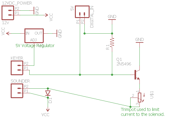
Schematic
06/06/2015 at 16:55 • 0 commentsThis is my first attempt to capture the schematic using Eagle. I welcome any constructive input on how to improve. I'm using a 12VDC power supply and limiting the current to the sounder using a trimpot. I selected a trimpot so that I can adjust to any sounder since they have varying resistance. I put the Keyer in the same loop as the digital signal so that I can drive the sounder with either an arduino/rpi or with the keyer. I used a 5v voltage regulator to limit the voltage on the bus since it's connected to the microcontroller board. I probably need a diode there, but I have an idea I want to explore, which is to have the wire going to the microcontroller to be used to send commands back to the board.
![]()
-
Power Supply
05/25/2015 at 02:13 • 0 commentsI've learned (luckily not the hard way) that I need to limit the current going to the solenoids to avoid damaging the sounder. There are a number of references, but I have not yet found a definitive source on what the proper current should be. Each sounder has a known resistance, so I'm going to experiment with a 12VDC Power Supply and will move a way from using the relay shield and replace it with a MOSFET. More to come.
Power Supply Sounder Current Limiting Resistor Current Worked? 12V 20 Ohm 100 Ohm 98 mA Y 12V 20 Ohm 150 Ohm 72 mA Y 12V 20 Ohm 220 Ohm 50 mA N