Alana B
-
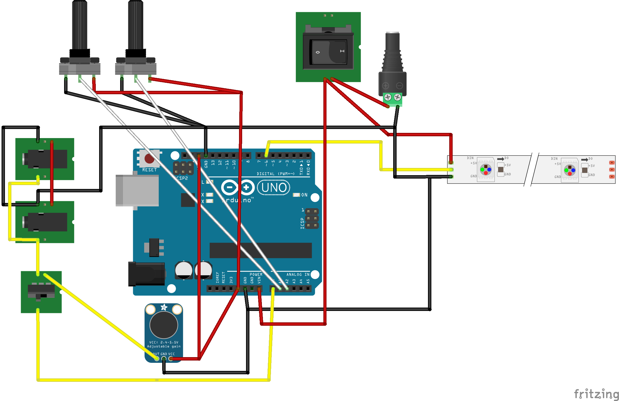
The Circuit
08/19/2014 at 22:44 • 0 commentsHere is the circuit I used. Pin 6 goes to the data channel of the neopixels, and they get power directly from the external power supply and are connected to common ground. The external power supply also powers the arduino via VIN, and the arduino is connected to common ground. The two pots are connected to common ground and get power from the Arduino's 5V. Their outputs go into Analog in A2 and A3. The electret microphone gets power from the arduino 5V as well and that is also connected to AREF. Its output goes into A1 if the toggle switch allows the connection.
The line input has the same connections as the microphone but is switched via the toggle switch. It also is wired in parallel to another headphone jack that is used as a THRU jack. It doesn't matter which is used as input and which is used as output; both will function even when the device is off as a THRU jack.
![]()
-
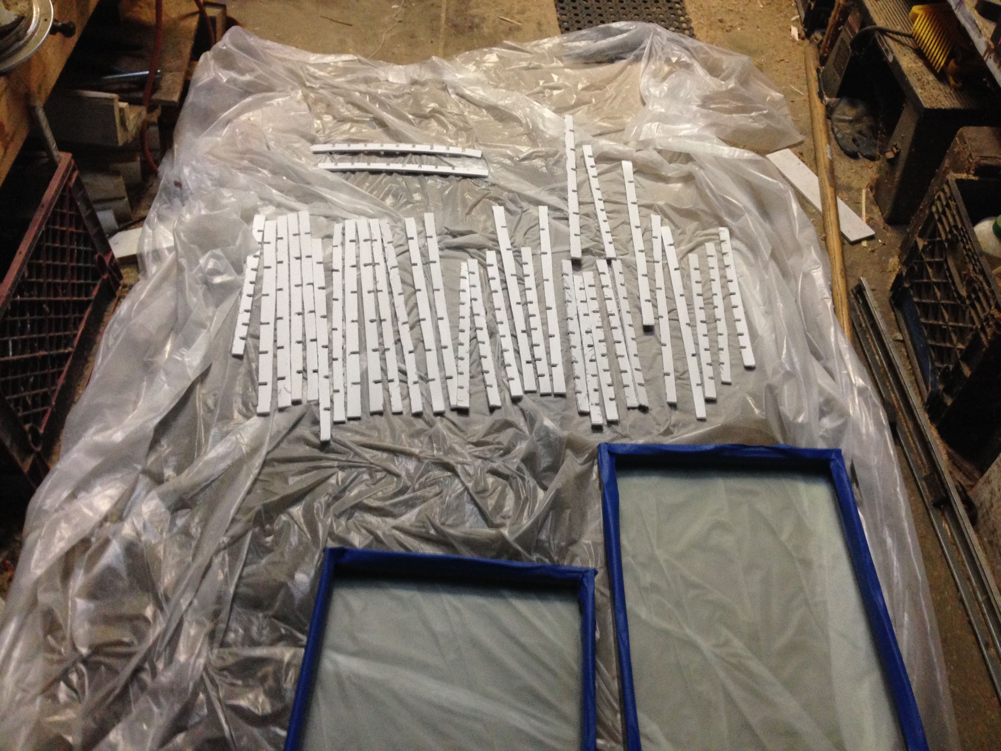
The Dividers
08/19/2014 at 22:25 • 0 commentsI bought some white poster board to divide the pixels up, and measured the width and height of inside the poster and its depth. I cut 6 row dividers and 9 column dividers for each frame, and then cut notches in each divider where they would intersect using a bandsaw.
I sprayed it with reflect all, which I found on amazon:
http://www.amazon.com/gp/product/B006VEEKRI/
I also masked the frame and then sprayed the glass with krylon reflected glass, on the inside of the poster:
http://www.amazon.com/gp/product/B00114LS5A/
That stuff works pretty well, I did two or three coats, but I would use more if I had it. It also seems to rub off when it gets bumped, so perhaps I would use real frosted glass next time.
![]()
-
Gluing & soldering the pixels
08/12/2014 at 16:07 • 0 commentsI bought 5 meters of the Adafruit 30 LED strips, or 150 pixels.
http://www.adafruit.com/products/1376
The poster frames would hold 10 pixels in a column, so I cut the neopixels into 10 LED strips. This left me with 15 strips, but since I wanted it to be even I used 7 on each poster and kept the extra 15th strip.
I divided the poster into even rows of 7 by 10 using a square ruler and then superglued the neopixel strips to the inside back of the poster. I alternated direction, snaking them up and down, to save on resistance in the whole circuit. I compensated for this with the programming. Then, I soldered the power, ground, and data lines back together to make one long strip again. I drilled holes in the back of the poster to stick the beginning and ends of the neopixel strips out of the back of the frame, and used JST connectors to connect the two frames together. Then I used a glue gun to reinforce all of the connections.
-
The Frame
08/12/2014 at 02:14 • 0 commentsI started by buying two 20" x 15" poster frames from target. I liked these ones because they were deep (1.5") which would be good for defusing light, and I just removed the clips that normally hold pictures inside of it. I initially thought I would use one enormous picture frame, but settled on these realizing I could use 2 and then it could fold for portability.
http://www.target.com/p/umbra-loft-6-opening-photoclip-frame/-/A-14126361#prodSlot=_1_20
Poster VU
A giant VU-meter housed in two poster frames with mic and line input and sensitivity and brightness knobs, powered by arduino and neopixels.