-
Programmer
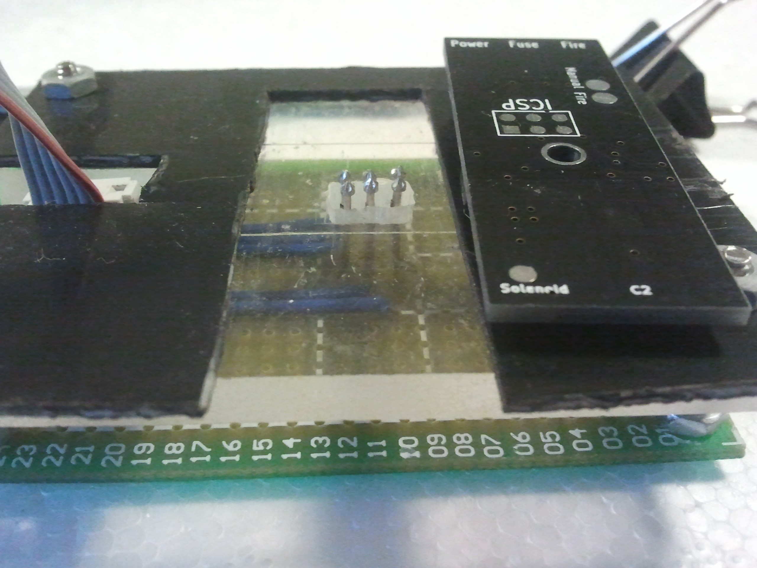
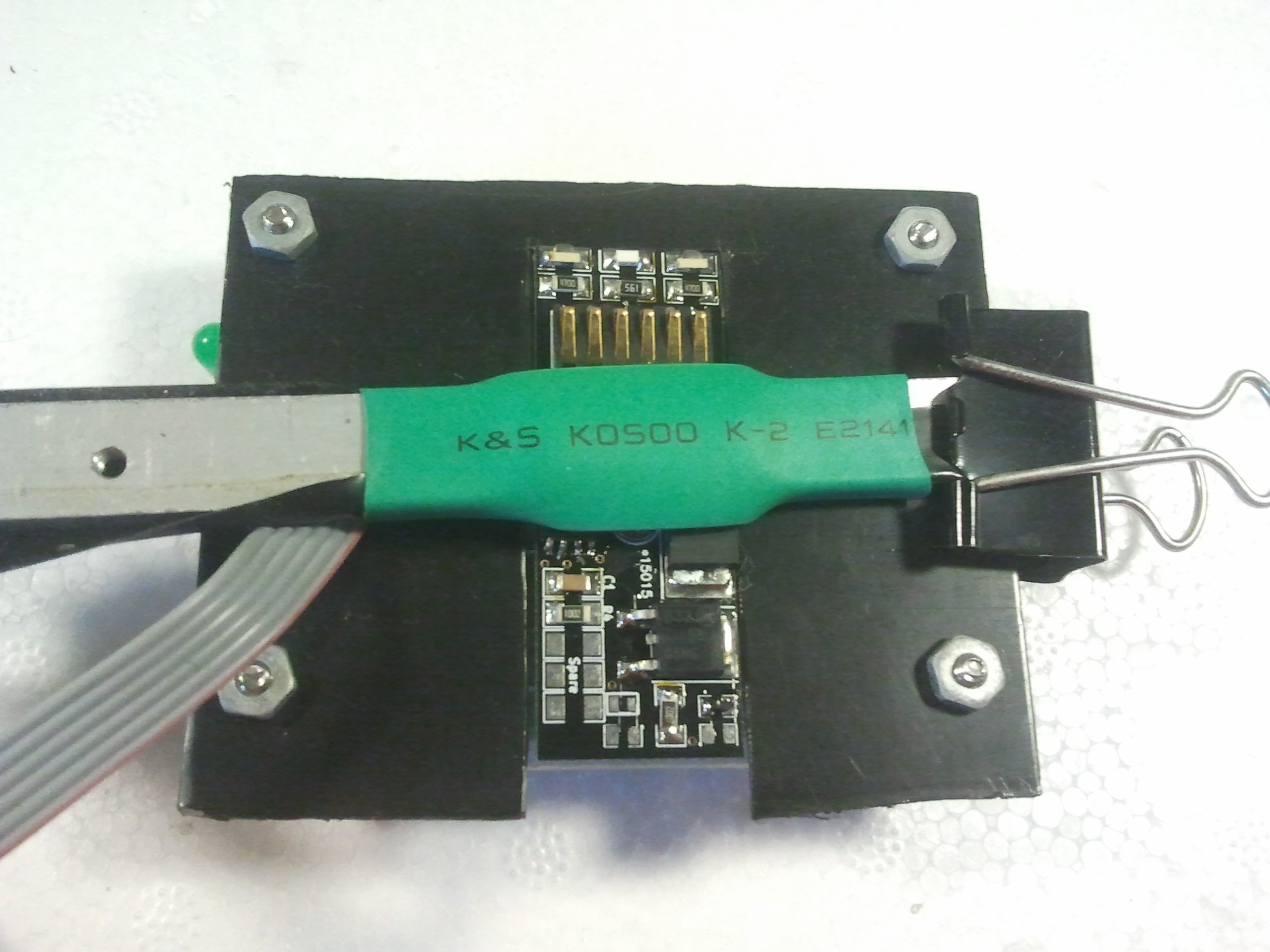
08/20/2014 at 17:48 • 0 commentsThe circuit boards use pads instead of pins for the ICSP connection, which means I use pogo pins to connect the programmer. I made a handy setup to hold the board in place while its firmware is loaded.

Unfortunately the black part that holds it in position is a little loose, so there's a bit of a jiggle required before it connects, but it's still much better than holding it myself.
The clip holds a scrap piece of aluminum with some shrink wrap on it. I can lift up the free end and slide the board in place. When I get it correctly positioned, the power LED lights, and I can program it.
I use electrical tape on the aluminium frame to prevent the pads on the bottom from shorting once installed.
-
Source
08/19/2014 at 00:45 • 0 commentsSource code, released under GPL 2
/** * Control for custom A5 electronic trigger * * Uses I2C to store settings and operate, with a switch as fallback * ATTiny45 * * * Copyright (C) 2013 Paint Race Inc. * * Author Nathan Gray * Released 2014-08-18 * * This program is free software; you can redistribute it and/or modify * it under the terms of the GNU General Public License as published by * the Free Software Foundation; either version 2 of the License, or * (at your option) any later version. * * This program is distributed in the hope that it will be useful, * but WITHOUT ANY WARRANTY; without even the implied warranty of * MERCHANTABILITY or FITNESS FOR A PARTICULAR PURPOSE. See the * GNU General Public License for more details. * * You should have received a copy of the GNU General Public License along * with this program; if not, write to the Free Software Foundation, Inc., * 51 Franklin Street, Fifth Floor, Boston, MA 02110-1301 USA. */ // Use i2c for commands & settings #include <TinyWireS.h> // For storing settings #include <EEPROM.h> // Default I2C Slave address #define I2C_SLAVE_ADDR 0x26 //#define I2C_SLAVE_ADDR B0100001 // i2c commands #define CMD_SET_ADDR 0x01 #define CMD_SET_ON_TIME 0x02 #define CMD_SET_OFF_TIME 0x03 #define CMD_SAFE_ON 0x0A #define CMD_SAFE_OFF 0x0B #define CMD_FIRE 0x10 // a5_a5_status #define STATUS_SAFE 0x00 #define STATUS_FIRE 0x0F // Pin definitions #define FIRE_PIN 4 #define MANUAL_PIN 3 #define INT_PIN 1 // Memory locations #define I2C_ADDR 0 #define ON_TIME_ADDR 1 #define OFF_TIME_ADDR 2 // Some safe defaults. solenoid should be good for 10% byte i2c_slave = I2C_SLAVE_ADDR; int on_time = 10; int off_time = 100; byte a5_status = STATUS_FIRE; void setup() { // Init pins pinMode(MANUAL_PIN, INPUT); digitalWrite(MANUAL_PIN, HIGH); pinMode(FIRE_PIN, OUTPUT); digitalWrite(FIRE_PIN, LOW); pinMode(INT_PIN, OUTPUT); digitalWrite(INT_PIN, HIGH); // Load settings, if there if(EEPROM.read(I2C_ADDR) != 0xFF) { i2c_slave = EEPROM.read(I2C_ADDR); on_time = EEPROM.read(ON_TIME_ADDR); // Off time should be at least 10x on time, but that could overflow a byte off_time = EEPROM.read(OFF_TIME_ADDR) * 10; } TinyWireS.begin(i2c_slave); // Wait to let the big cap charge delay(500); } void loop() { if(digitalRead(MANUAL_PIN) == LOW) { fire(); } byte byteRcvd,i = 0; int in = 0; if (TinyWireS.available() > 0){ // got I2C input! byteRcvd = TinyWireS.receive(); // get the byte from master switch(byteRcvd) { case CMD_SET_ADDR: byteRcvd = TinyWireS.receive(); if(byteRcvd >= I2C_SLAVE_ADDR && byteRcvd <= I2C_SLAVE_ADDR + 1) { EEPROM.write(I2C_ADDR, i2c_slave); TinyWireS.send(i2c_slave); // Need to reset now... } break; case CMD_SET_ON_TIME: on_time = TinyWireS.receive(); EEPROM.write(ON_TIME_ADDR, on_time); TinyWireS.send(on_time); break; case CMD_SET_OFF_TIME: in = TinyWireS.receive(); in |= (TinyWireS.receive() << 8); if(in > on_time * 100) { off_time = in; } else { off_time = on_time * 100; digitalWrite(INT_PIN, HIGH); delay(50); digitalWrite(INT_PIN, LOW); } EEPROM.write(OFF_TIME_ADDR, off_time); TinyWireS.send(off_time); break; case CMD_SAFE_OFF: a5_status = STATUS_FIRE; //blinky(3); break; case CMD_SAFE_ON: a5_status = STATUS_SAFE; break; case CMD_FIRE: fire(); break; } } digitalWrite(INT_PIN, a5_status == STATUS_SAFE ? HIGH : LOW); } // Debug void blinky(int times) { for(int i = 0; i < times * 2; i++){ digitalWrite(INT_PIN, i % 2 == 1 ? HIGH : LOW); delay(100); } } void fire() { if(a5_status == STATUS_SAFE) return; digitalWrite(FIRE_PIN, HIGH); delay(on_time); digitalWrite(FIRE_PIN, LOW); delay(off_time); } -
Libraries
08/16/2014 at 23:58 • 0 commentsThe firmware uses the Arduino EEPROM library:
http://arduino.cc/en/Reference/EEPROM
and the TinyWire library:
https://github.com/rambo/TinyWire
as well as the Arduino-Tiny core:
-
Firing demo
08/16/2014 at 23:24 • 0 commentsWhat good is this without video of it firing?
The mount on the test stand and on the buggy.
It doesn't show up on the video, but there is another green LED that lights when firing.
-
Introduction video
08/14/2014 at 03:19 • 0 commentsWow. Making the thing is easier than making the video.
I'm now even more impressed by those who make high quality videos clearly and concisely demonstrating something.
This video introduces some of my other attempts and reasons for wanting to build this one.
Paintball Marker Mount
A replacement handle for a paintball marker so you can easily mount it on vehicles, robots or turrets