surfingsteve
-
Phase 1 - Success
08/21/2014 at 05:27 • 0 comments![]()
I am able to send pings over the nRF24 interface using the custom protocol. The code right now is just a proof of concept, and can be considered in the pre-alpha stage. However I do plan on releasing it soon on Git-hub, as soon as I can clean it up a bit. In the video the top two windows are connected to the first raspberry pi, and the bottom two windows are connected to the second raspberry pi. The windows on the left show the debug output from the nRF24 link.
Jump to 1:27 to see the good part.
-
Youtube Intro - 2min
08/21/2014 at 03:36 • 0 commentsVery high level overview of the project posted on youtube. More details here in the log.
-
Tap/Tun Overview
08/20/2014 at 06:52 • 0 commentsCentral to this project is using a Raspberry Pi, or similar linux device, to act as a bridge between the internet and the nRF24L01+ device. Our task includes two steps. First we create a network driver for the nRF24L01+. Second we bridge this new device we created with the ethernet port on the Raspberry Pi. Wikipedia: Network Bridging Alternatively we could setup Routing, IP Masquerading (NAT) or any other linux network techniques to our newly created interface, but that discussion is beyond the scope of this hack.
Building a network device driver in linux requires kernel device programming (not as hard as it sounds) and constant updates with each new kernel release. This can be a lot of work and a pain to maintain your code. Fortunately there is a way in software to create a virtual network interface that can be initialized by a simple C program. This is a trick often used by VPN clients in linux to create virtual network interfaces to a remote network.
There are two types of virtual network interfaces in Linux, TAP and TUN. Paraphrasing Wikipedia, both devices are purely created in software. TUN, short for tunnel, simulates a layer 3 IP communications, think IP addresses. TAP, short for network TAP, simulates layer 2 data link communications, think MAC addresses. Now might be a good time to review the network Wikipedia: OSI layer model.
For our project we are going to use the TAP interface. This allows us to operate at the layer 2 level and forward ethernet data in a more raw form. We just have packets of bytes we want to shuttle back and forth with no concept in our software of IP addresses, IPv4/IPv6 or TCP/UDP. These are all things we can support without having to know anything about then. This is an advantage of the network OSI model. This gives us great flexibility of being protocol agnostic. Our nodes can use DHCP, send network broadcasts, or communicate in IPv6. Our hardware doesn't know or care because it's all bytes to us at the layer 2 level. As a side note the RF modulation would be the layer 1 level in this use case, but for now that's a detail we can safely ignore.
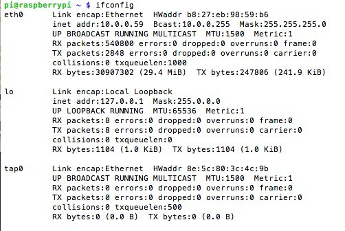
Here is a quick example of a tap interface on a linux machine:
![]()
-
Packet Structure
08/20/2014 at 06:06 • 0 commentsThe maximum size that a RF24L01+ can transmit is 32 bytes. An ethernet frame can contain up to 1500 bytes. We need to define a very simple protocol that will allow us to transmit the larger 1500 byte ethernet frames over the limited 32 byte messages that are sent via the RF24L01+.
The full Ethernet frame is broken up to small 29 byte size packets to transmit over the wireless link. The additional 3 bytes of overhead are used to help reassemble the frame on the receiving end of the link. A random ID is generated to identify the packets belonging to the same frame. We rely on the CRC that is already generated by the RF24L01+ to ensure the messages we receive are correct. This is acceptable because the RF24L01+ has a mode that automatically calculates and sends a CRC with the transmission of every 32 byte packet. When the 32 byte packet is received on the other end the CRC is checked, and if found to be incorrect it is automatically re-requested before passing the data to us. An additional CRC in our code would be wasteful overhead.
Structure
- 2 bytes - random "packet id", only used to identify each particular ethernet frame
- 1 byte - control
- 7 - start bit - indicates this is the first packet of the ethernet frame
- 6 - stop bit - indicates this is the last packet of the ethernet frame
- 5:0 - uint count - value 0->63 *
- 29 - bytes data, zero pad end for last packet
*The count variable is an integer index for each of the RF24L01+ transmitted packets. For example, [0,1,2,3...n]. This helps the receiving end place the data from each RF24L01+ packet into the correct location of the reassembled ethernet frame. The only exception is with the "last" 29 byte packet. If the last flag is set to 1, then the count variable identifies how many bytes are contained in this last packet. The rest of the packet will be 0 padded.
Example - ethernet frame (the data used here is gibberish)
(0x00 repeated 29 times) (0x01 repeated 29 times) (0x02 repeated 4 times)
- or -
0x00 0x00 0x00 0x00 0x00 0x00 0x00 0x00 0x00 0x00 0x00 0x00 0x00 0x00 0x00 0x00 0x00 0x00 0x00 0x00 0x00 0x00 0x00 0x00 0x00 0x00 0x00 0x00 0x00 0x01 0x01 0x01 0x01 0x01 0x01 0x01 0x01 0x01 0x01 0x01 0x01 0x01 0x01 0x01 0x01 0x01 0x01 0x01 0x01 0x01 0x01 0x01 0x01 0x01 0x01 0x01 0x01 0x01 0x02 0x02 0x02 0x02
This results in being parsed into:
nRF24 packet 0 - 0xba 0x02 0x80 0x00 0x00 0x00 0x00 0x00 0x00 0x00 0x00 0x00 0x00 0x00 0x00 0x00 0x00 0x00 0x00 0x00 0x00 0x00 0x00 0x00 0x00 0x00 0x00 0x00 0x00 0x00 0x00 0x00
nRF24 packet 1 - 0xba 0x02 0x01 0x01 0x01 0x01 0x01 0x01 0x01 0x01 0x01 0x01 0x01 0x01 0x01 0x01 0x01 0x01 0x01 0x01 0x01 0x01 0x01 0x01 0x01 0x01 0x01 0x01 0x01 0x01 0x01 0x01
nRF24 packet 2 - 0xba 0x02 0x44 0x02 0x02 0x02 0x02 0x00 0x00 0x00 0x00 0x00 0x00 0x00 0x00 0x00 0x00 0x00 0x00 0x00 0x00 0x00 0x00 0x00 0x00 0x00 0x00 0x00 0x00 0x00 0x00 0x00
packet 1
0xba 0x02 - random packet id
0x80 - start bit 7 set, stop bit 6 cleared, count = 0 (packet index)
0x00 repeated 29 times - data payload
packet 2
0xba 0x02 - random packet id
0x01 - start bit 7 cleared, stop bit 6 cleared, count = 1 (packet index)
0x01 repeated 29 times - data payload
packet 3
0xba 0x02 - random packet id
0x01 - start bit 7 cleared, stop bit 6 set, count = 4 (valid bytes in this last packet)
0x02 0x02 0x02 0x02 (0x00 repeated 25 times) - data payload, only first 4 bytes valid
Notice how the random packet id is the same id for each ethernet frame. The packet only changes with each new ethernet frame. This allows us to have multiple nodes broadcasting segments of different ethernet frames to the root node and still provide the root node with enough information to reassemble the frames.
-
Proof of Concept
08/20/2014 at 05:22 • 0 commentsIn order to determine the feasibility of this idea first I wanted to implement a simple Raspberry Pi to Raspberry Pi, two node link. In an ideal case we want a network similar to WiFi with a single access point and multiple nodes.
$0.87 WiFi for Raspberry Pi and Arduino Projects
My project goal is to make internet access for micro controllers dirt cheap and dead simple to implement in your own projects.