-
PCB Digit Reflow and Test
04/04/2015 at 15:00 • 0 commentsWell I finally got my new PCBs from DirtyPCBs.com. I had all my parts from my Digikey BOM. I had some solder paste from SparkFun. And of course I also had a Polyimide stencil I ordered from OSHStencils. All in all it was a great success. The unmodified toaster oven performed it's reflow job great. All the LEDs lit, and the board to board chaining seemed to work great as well. More details on my blog.
![]()
A simple diffuser in front of those LEDs would create a very nice display.
-
Reflow Test For Digit PCBs
03/16/2015 at 12:29 • 0 commentsI'm still waiting for my latest boards to get here for my double digit LED displays, but in the mean time I picked up a used toaster oven at Goodwill for $10 bucks and did a quick reflow test. Results were good and I'm waiting to get my new boards in and start assembling a few.
-
Working Mini Test Display
02/20/2015 at 07:48 • 0 commentsAlthough I think I will go away from the multiplexed display for the final design, I still thought this was a neat little prototype build. For the final display, since it will be large, and I think I have settled on using PCBs and SMT LEDs for the digits, I'll keep with the shift register Idea, but have a transistor per segment so I can just shift data across the display instead of trying to multiplex it. I just put up a short blurb about the board over at my blog site.
-
Mini Test Display
02/05/2015 at 04:05 • 0 commentsI though a good little board for testing out the shift register multiplexed display would be to make a little board using some Ebay special common anode 7 Segment displays. I've got that board on order over at OSHPark.
https://oshpark.com/shared_projects/YzQBaEu3
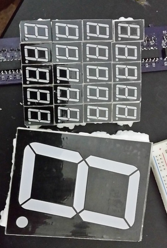
Here are the small displays next to a larger 3-1/2 inch digit I also got off of EBay.
![]() Thinking about it more, while I'll complete the mutliplexed display test, when building larger displays, it may be more troublesome to run the 8 power wires to each digit, then it would be to run 2 power wires and 3 signal wires with some local circuitry to drive each digit. I'm thinking possibly a BCD decoder and a shift register to power each digit, feeding the serial out to the next digit. In that way the display could be refreshed by sending 72 bits, rather than constantly having to drive the multiplexed display.
Thinking about it more, while I'll complete the mutliplexed display test, when building larger displays, it may be more troublesome to run the 8 power wires to each digit, then it would be to run 2 power wires and 3 signal wires with some local circuitry to drive each digit. I'm thinking possibly a BCD decoder and a shift register to power each digit, feeding the serial out to the next digit. In that way the display could be refreshed by sending 72 bits, rather than constantly having to drive the multiplexed display. -
Casual Testing
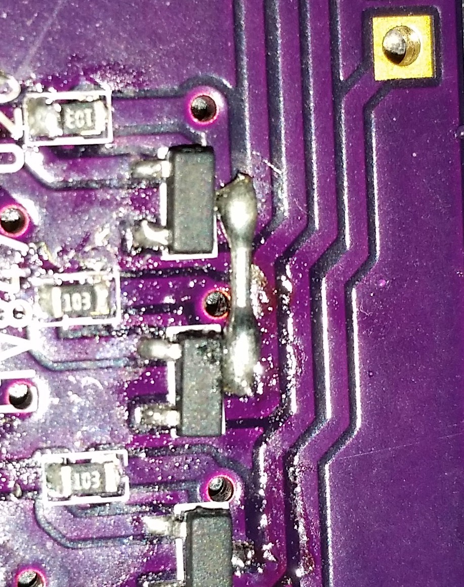
01/24/2015 at 17:25 • 0 commentsjust doing some casual testing of my driver board. The low side MOSFETs worked perfectly, on with a low input to the opto coupler, and off when that input goes high. However, the high side FETs had a slight issue, the were mostly on by default and then all the way on with the high input to the coupler. Uh oh. Well looking online at some reverence designs showed I wired the P channel FET wrong, swapping the gate and the source pins. I think this explains the behavior, as my mostly on condition was about 1.2 volts below Vcc, which I think would be the forward biased drop off the body diode. Not all is lost though, by carefully removing the FET, flipping it upside-down, and rotating it I was able to get two pins soldered to the right pads, and run a fine wire to the gate. 16 times. I've got about 6 left and I used up my two spares. Desoldering these with the iron is tough, as the lightest pull will rip the pin out of the package. Tests on the fixed FETs succeded, though. I'll have to update the schematic and board layout when I can.
-
Power Driver Board
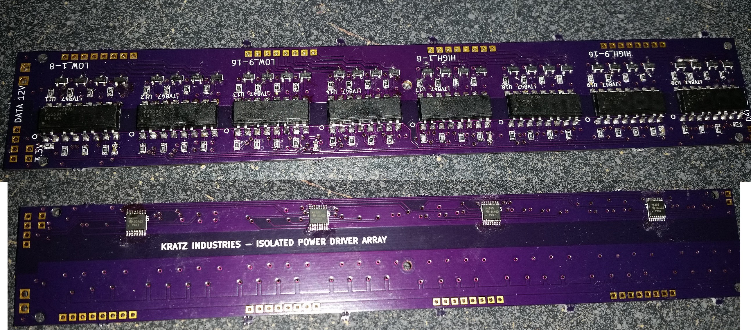
01/10/2015 at 18:46 • 0 comments![]()
Just wanted to post the picture of my serial in driver board I made for this project. This module of the project is meant to take in serial data on the low 3.3v side, and latch it out through some opto-isolators to an array of n and p channel mosfets. 16 sources and 16 drains for a 16x16 multiplexed matrix, or whatever else you may want to do with it. The input is 4 pins, clock, latch, high data, and low data. Only one mistake, a disconnected pin that was fixed with a short jumper.
![]()
Anyways, I've ordered some small 7 segment displays from EBay, as well as a sample 3 inch 7 segment display to do some testing on. Many options for the board display, may have to go a bit smaller than originally planned for the first one. Testing the driver board is the next step for this project.
-
Lunchbreak 12-2-14
12/02/2014 at 18:53 • 0 commentsProgress is slow, as is the norm with my projects. Attempting to allocate time among my other life responsibilities continues to be one of my weaker skill. Especially when my bed is so soft.
Anyways, I dI'd get the small power supply board working work 3.3v output. The first attempt somehow ended up with most of the QFN pins connected to ground. A more careful second soldering attempt fixed that.
I got the drive board done and soldered, but as of yet untested. Im currently sick on the physical design of the digits. Part of me wants to get a test setup going and the other part wants to make a nice looking digit assembly. Maybe after Christmas I can order out some nice laser cut parts.
I've also thrown my hat into the Trinket design contest, so I will have to fit that in as well.
-
10-8 Lunchbreak
10/08/2014 at 17:57 • 0 commentsWhile I did do some soldering last night, it ended in failure. I don't know what it is, but everything seems much bigger on the layout than real life. The 3.3V power supply board used a converter chip that was absolutely microscopic QFN while attempting to hand solder. Got it all together, no blue smoke bUT also no output. Likely one of the pins is not connected. I also had trouble soldering amy pounds on the board that were connected to the ground plane. Oh well, I'll try and de bug it, but it's just a power supply and easily replaced by something else.
-
Lunchbreak 10-2-14
10/02/2014 at 17:58 • 0 commentsWell, I've sent out my LED drive board and ordered the parts. The board proved to be large with the optocouplers, at seven inches long it cost $50 frim OSHPARK. Perhaps I should have stayed with the discreet transistor version for the FET gate drive? Hopefully the isolation aspect will give it a small bit of reusability. I may make a sized down version of the board for future use, some I don't think my design requires isolation from the 12 supply. But, for the moment reworking the board for lower cost would have just delayed getting a prototype built. So we will stick with that. I've updated Github with these latest changes.
-
10-1-14 Lunchbreak
10/01/2014 at 17:58 • 0 commentsIt's been a while since I've done an update. The board layout for the 32 channel driver is almost done. I may add in some footprints for some flyback diodes before I call it completed, just for the sake of reusability. Then I think ill send that off to OSHPARK, and order my parts for the first two boards so i can get assembling and testing.
Wi-Fi Controlled Open Scoreboard
A open design for a portable scoreboard that can be controlled over Wi-Fi, and integrated into event management software.

 Thinking about it more, while I'll complete the mutliplexed display test, when building larger displays, it may be more troublesome to run the 8 power wires to each digit, then it would be to run 2 power wires and 3 signal wires with some local circuitry to drive each digit. I'm thinking possibly a BCD decoder and a shift register to power each digit, feeding the serial out to the next digit. In that way the display could be refreshed by sending 72 bits, rather than constantly having to drive the multiplexed display.