When assembling the bin, I did not add the divider. In addition, I assembled all parts except one of the ends and the bin door.
2
Assemble all Feather and and Wings
Following the instructions on Adafruit, assemble the feathers
Kitchen Unit:
Use Huzzah Feather and TFT featherwing; regular headers are fine here (you may need to trim them to fit flush against the TFT)
Adafruit Huzzah (ESP8266)
Adafruit TFT Featherwing
Base Unit:
Huzzah and RFM69HCW Feather. Use short stacking headers for the Huzzah.
Note - be sure to choose the correct freuqency for your location (815 - Europe, 900 Americas, 433 - Asia)
Adafruit Radio FeatherWing - RFM69HCW 900MHz - RadioFruit
Compost Unit
32u4 Feather with RFM69 and Proto wing; short stacking headers are suitable here as well.
Adafruit Feather 32u4 RFM69HCW Packet Radio - 868 or 915 MHz - RadioFruit
FeatherWing Proto -
3
Download and print all 3D files
Using the STL files in the GitHib library, print all the 3D files
4
Request API access on Compostprofessor.com (coming soon) and update ino files
Go to CompostProfessor.com and request API access to the Compost Professor Cloud. Update the *.ino files to reflect the API access key and the Compost Unit name
[Note: the ability to request an access key will be available in Nov/Dec 2017).
5
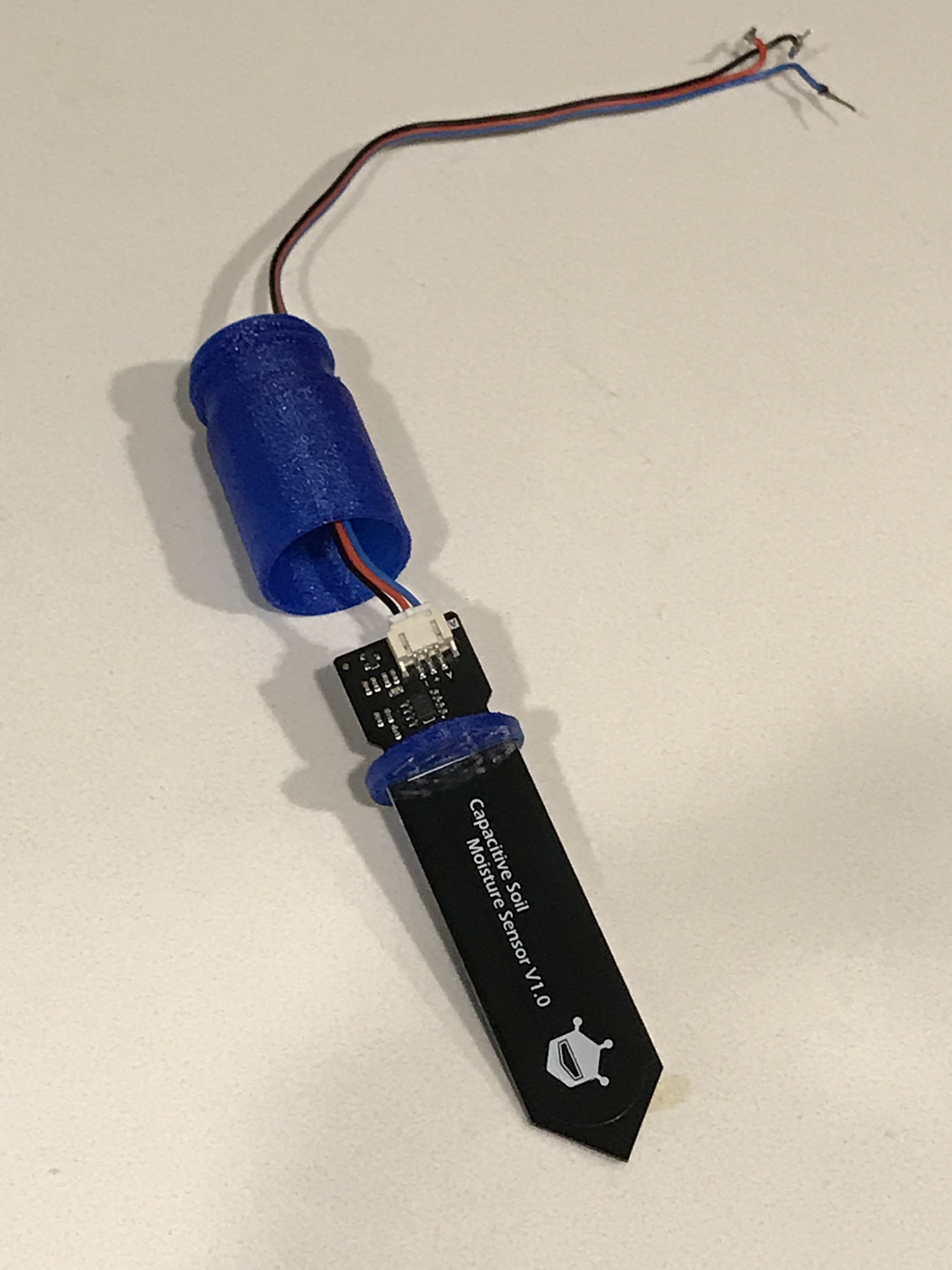
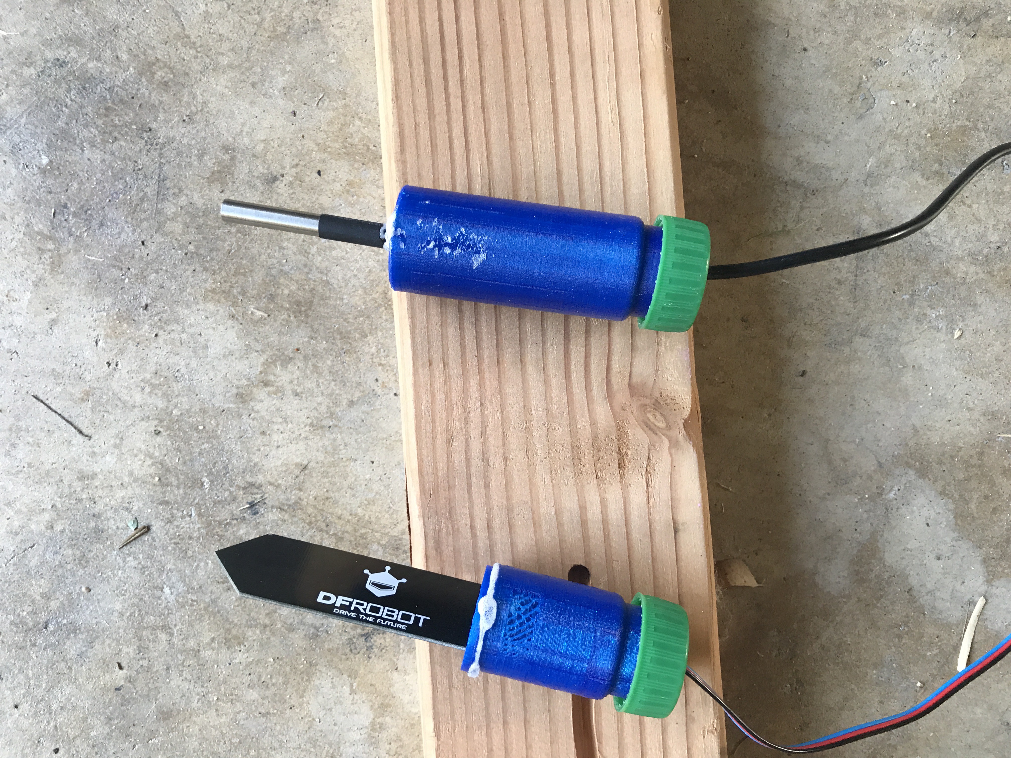
Ready Moisture and Temperature Sensors for Compost Bin
Ensure that all sensors have at last 4-6 feet of cable and have been wrapped with heat shrink.
Moisture Sensor
Use conformal coating on the top of the moisture sensor (to the line)
After it drys, insert the moisture sensor into the Moisture Cap
Assemble the Moisture Cap on top of the Moisture Case, and use silicone sealant and Gorilla Glue (after the silicone dries) to secure the case.
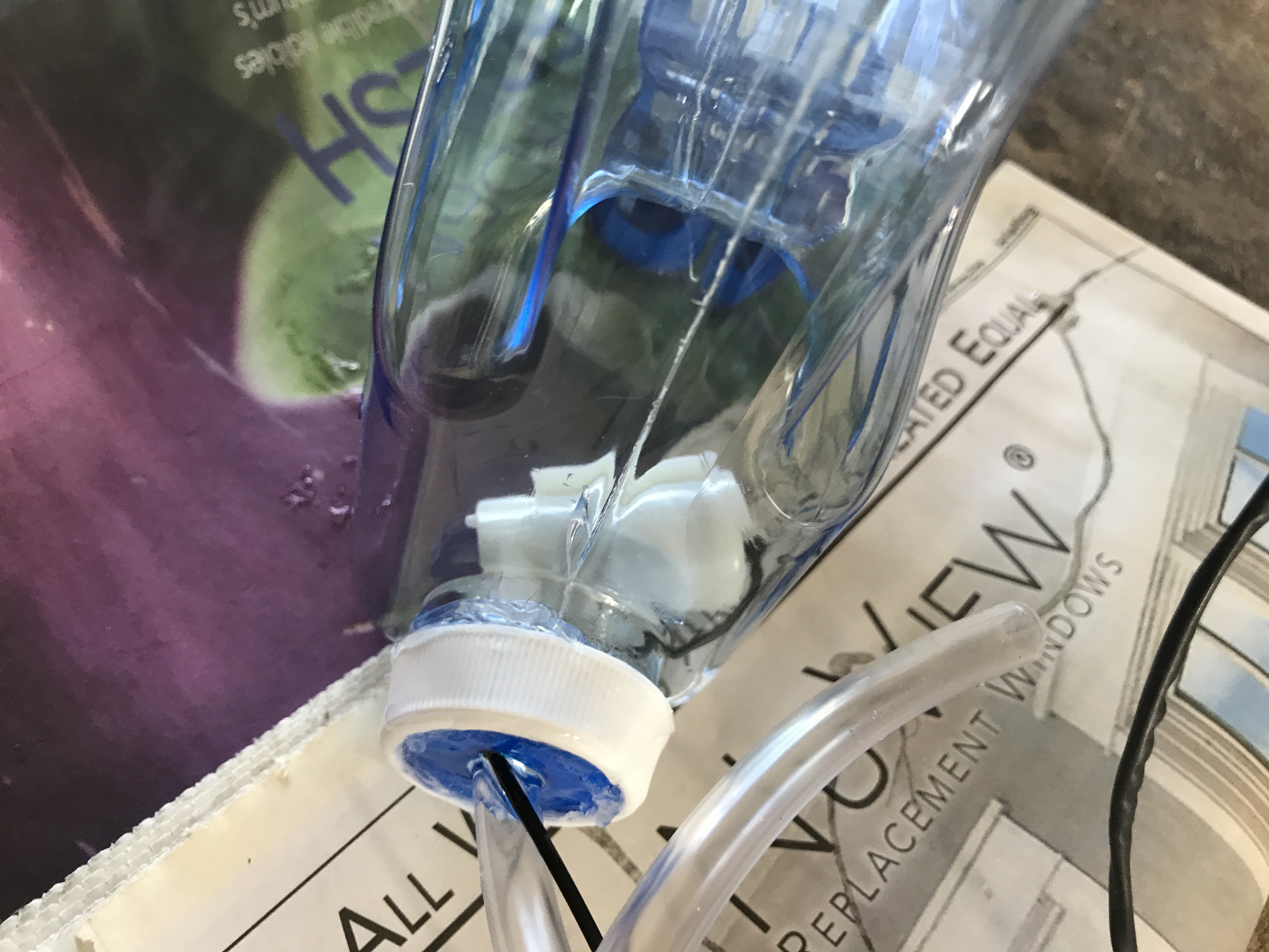
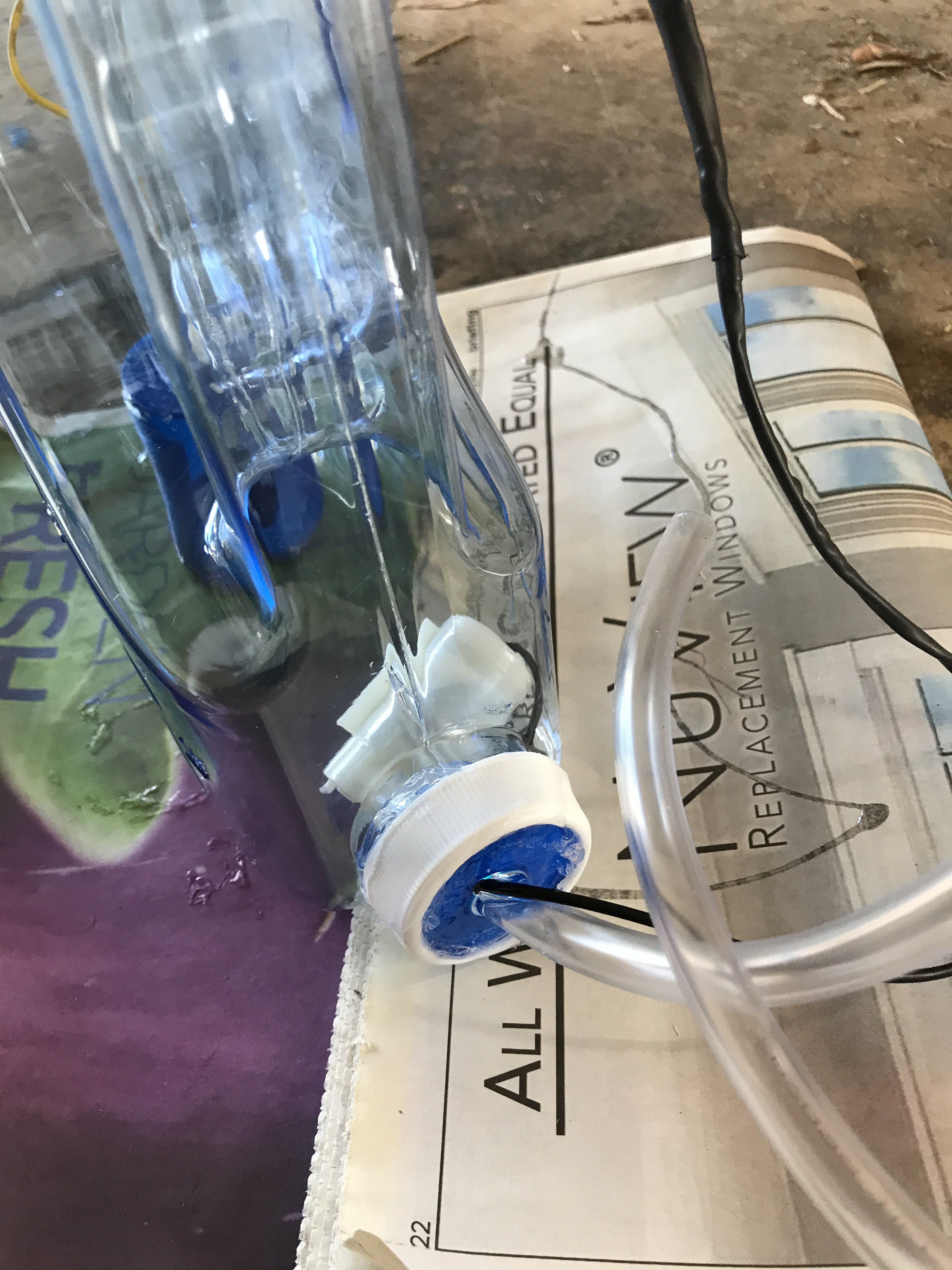
Drill a hole into an old soda bottle top and string the cables through the hole
Screw the bottle top onto the Moisture Case and secure with silicone and glue.
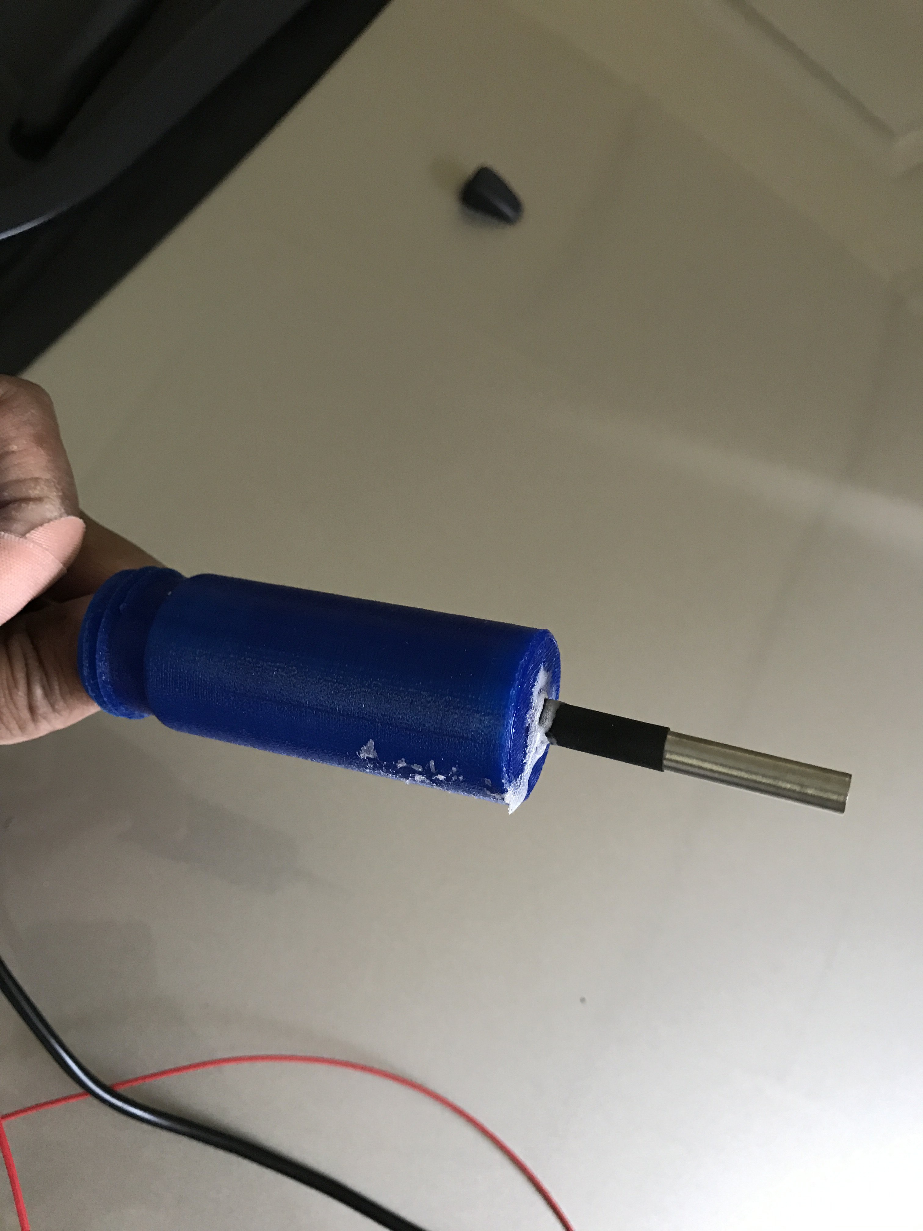
Temperature Sensor
Insert the temperature sensor into the small hole at the end of the Temperature Case
Use glue to secure the sensor into place
Drill a hole into an old soda bottle top and string the cables through the hole
Screw the bottle top onto the Temperature Case and secure with silicone and glue.
Final Product
6
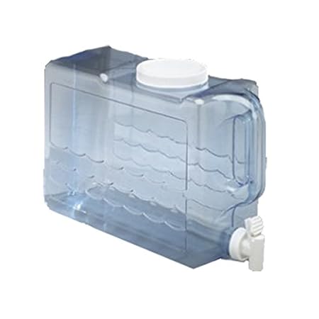
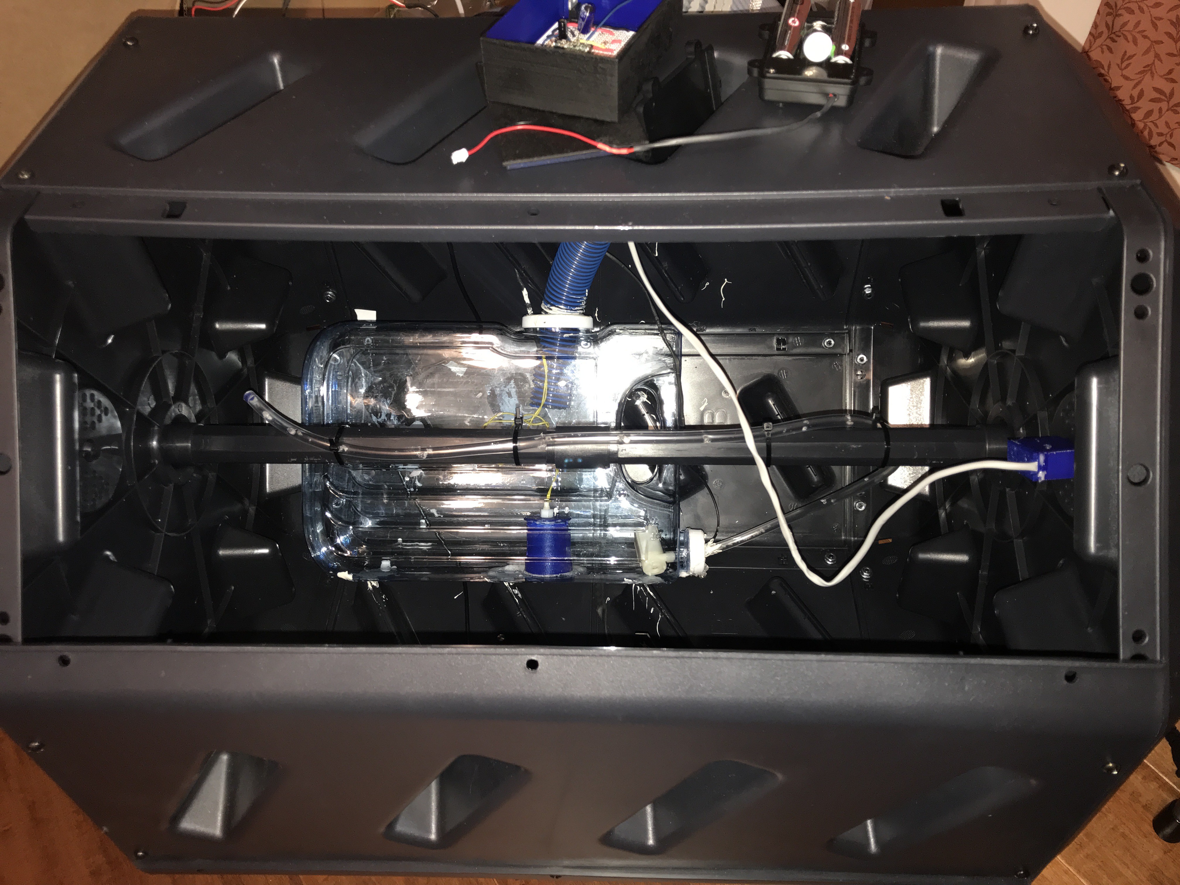
Assemble Water Reservoir
Components Needed:
Slimline Beverage Container
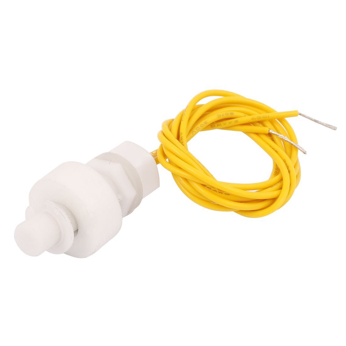
Water Float
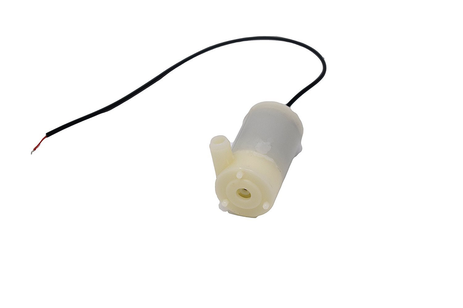
Water Pump (note - you will use the same power source to power the microprocessor and the pump. Therefore, the pump needs to be able to operate at a low voltage).
Gorilla Glue
Silicone adhesive
Water Reservoir Case and Cap 3D prints
Reservoir Spigot 3D print
Hose Cap 3D print
Plastic Bottle top
1.5 inch Inner diameter Spa Hose (1 foot)
3/8 inner diameter Vinyl Hose 5 feet
Exopy
Prep-work
Remove the top and spigot from the beverage container.
Extend the length of the cables to 4-6 feet. Note - Because these components will be in water, ensure that the original cables connected to the Water Pump and Float are long enough to clear the reservoir. If they are not long enough, then you will need to waterproof the connections when lengthening the cable.
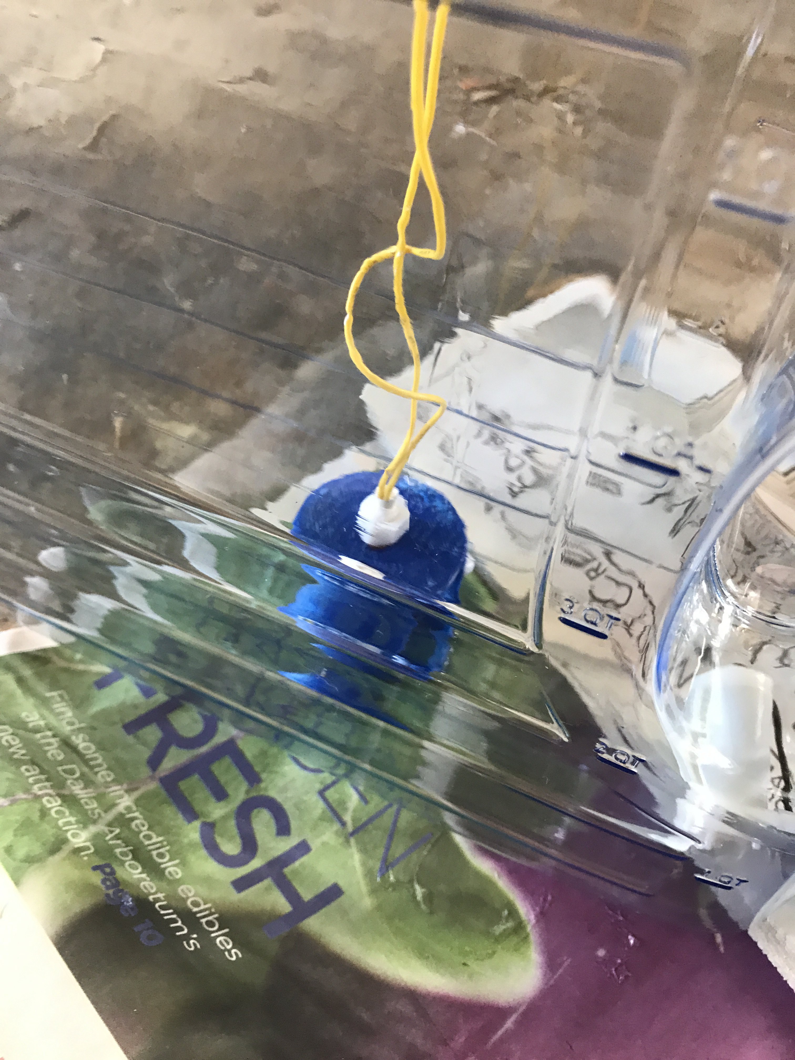
Water Float
Screw the Water Float into the Water Float Cap
Secure the Water Float Cap to the Water Float Case with glue.
Once the cap is dry, add glue to the bottom of the Float Case and lower the case into the Water Reservoir.
Water Pump
Attach a hose to the pump and secure with glue or a clamp
Insert the hose and the pump wires through the Reservoir Cap
Insert the pump into the spigot opening and screw the Reservoir Cap in place with the original spigot screw ring
Use silicone adhesives around the opening and Reservoir Cap. When dry, apply glue.
Assemble Water Reservoir
Insert the flow cap into the vinyl hose and secure with glue
Drill holes approximately 2 inches apart into both sides of the vinyl hole. Start with smaller holes closer to the pump and larger holes towards the end.
Drill an 1/2 in holi into the larger beverage case top and insert the Spa Hose
Secure the case top with silicone and glue.
Install Water Reservoir
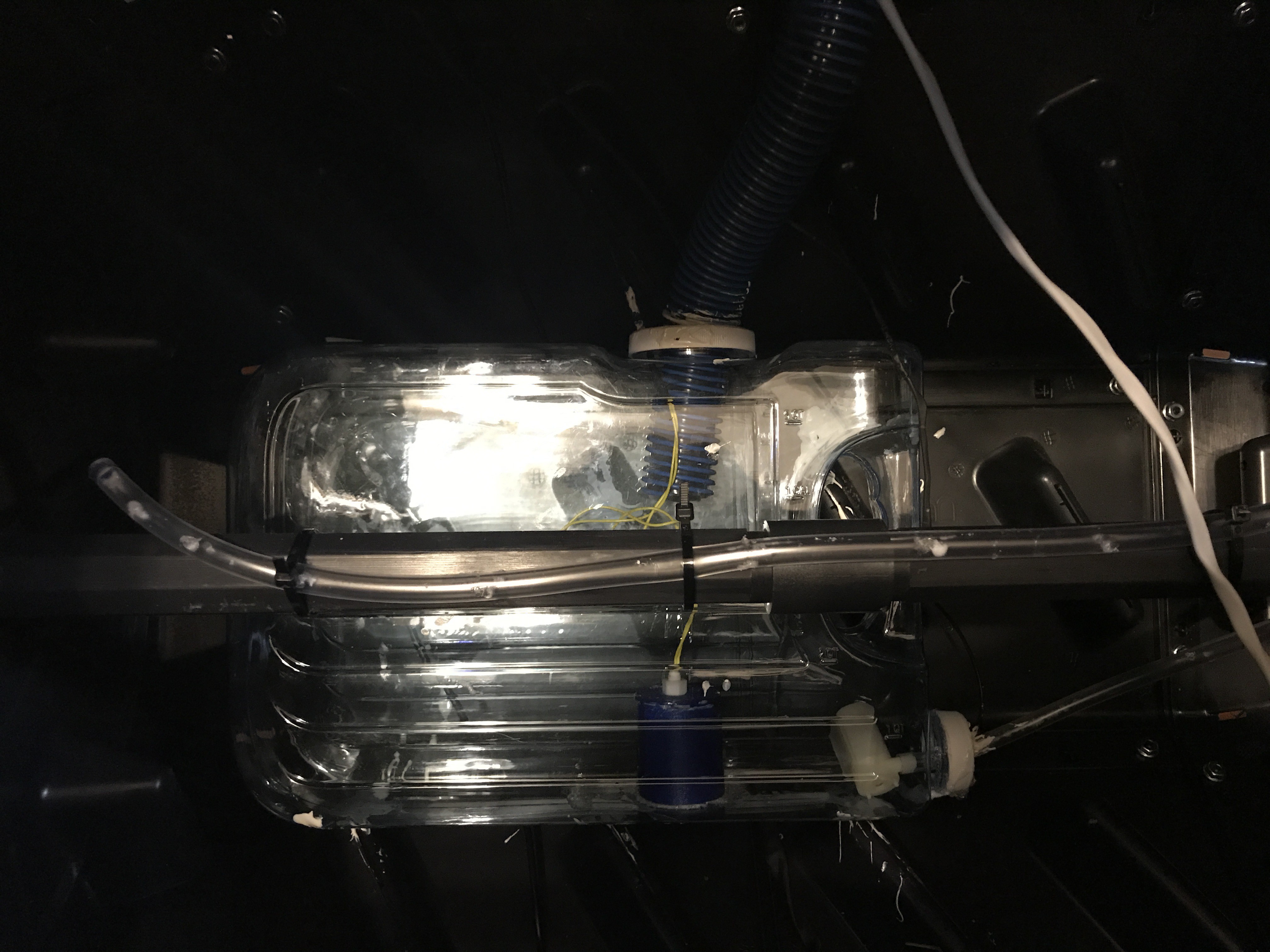
Place the water reservoir into the bin and mark where the hose meets the top and where the reservoir is flush with the bin. Remove the reservoir.
Drill a 1/2 in hole where the hose meets the top.
Mix a small batch of epoxy and apply the epoxy to the inside of the bin where it reservoir will sit.
Place the reservoir on the epoxy and weigh down the reservoir with books until the epoxy dries.
Once the epoxy dries, insert the Reservoir Spigot (the 3D printed object) into the hole.
Attach the Spa hose around the spigot and glue all pieces with epoxy.
When dry, screw a plastic bottle top to the spigot.
Arrange the vinyl hose (e.g. the "watering hose, with the holes") along the length of the center beam and attach with cable ties.
7
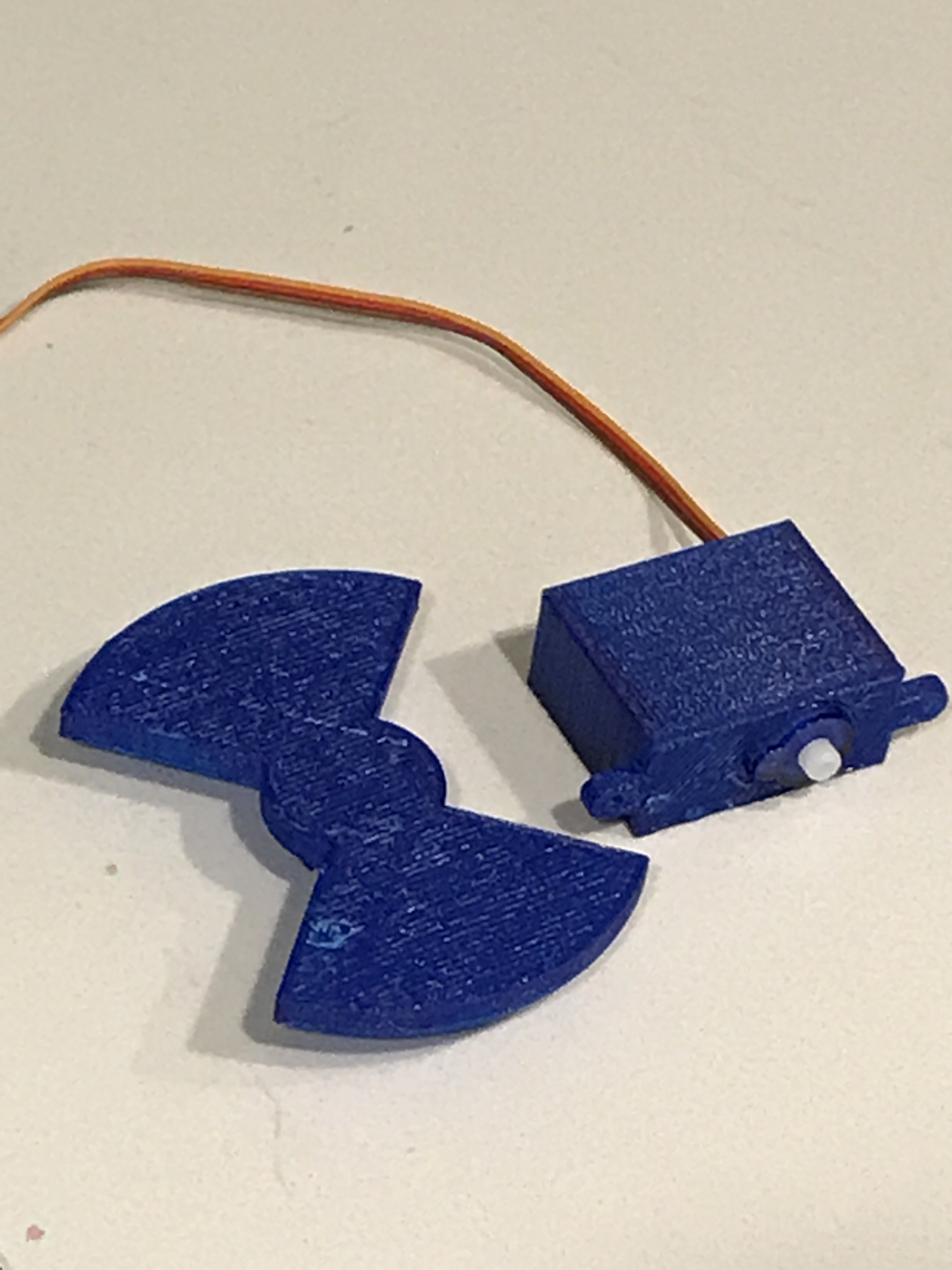
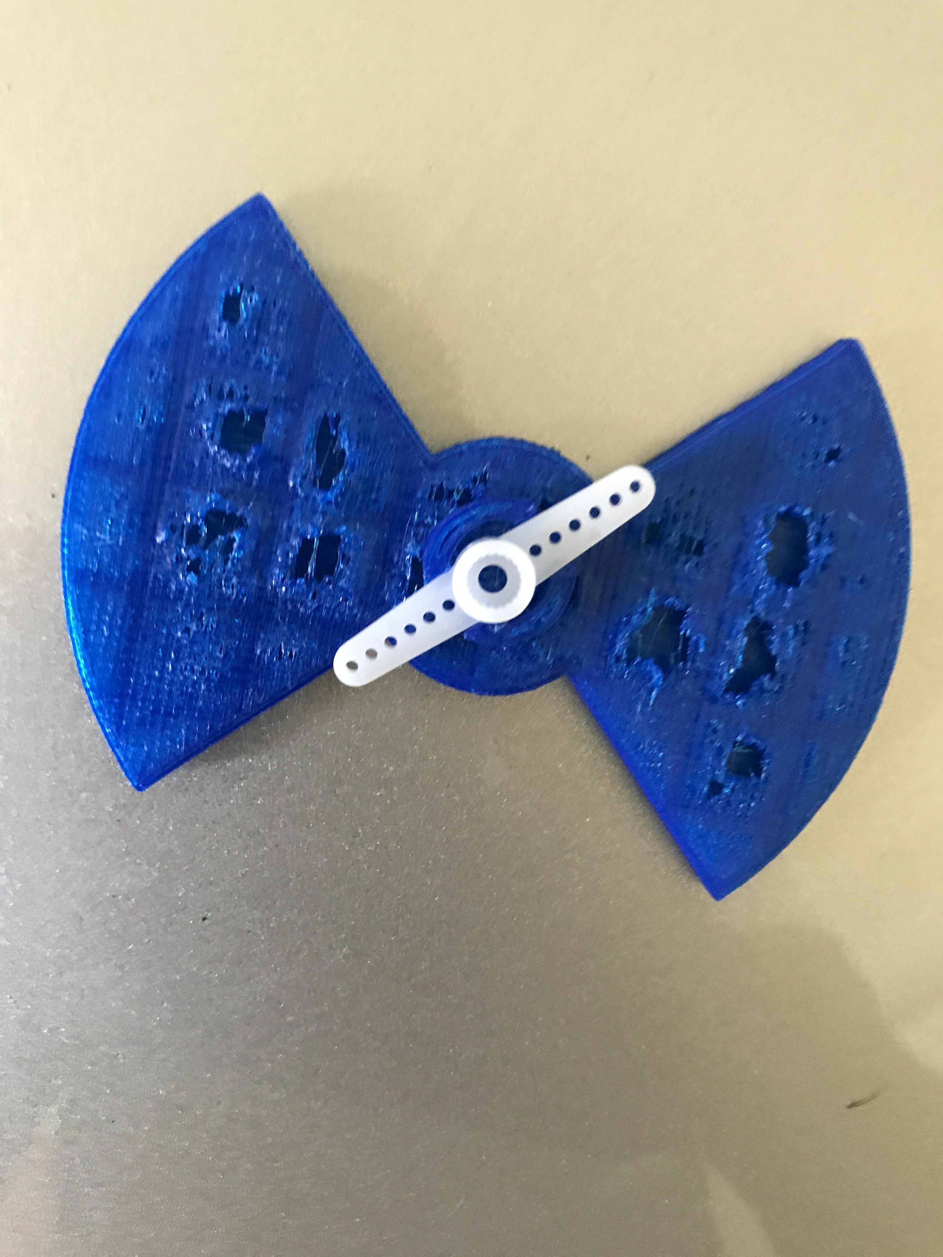
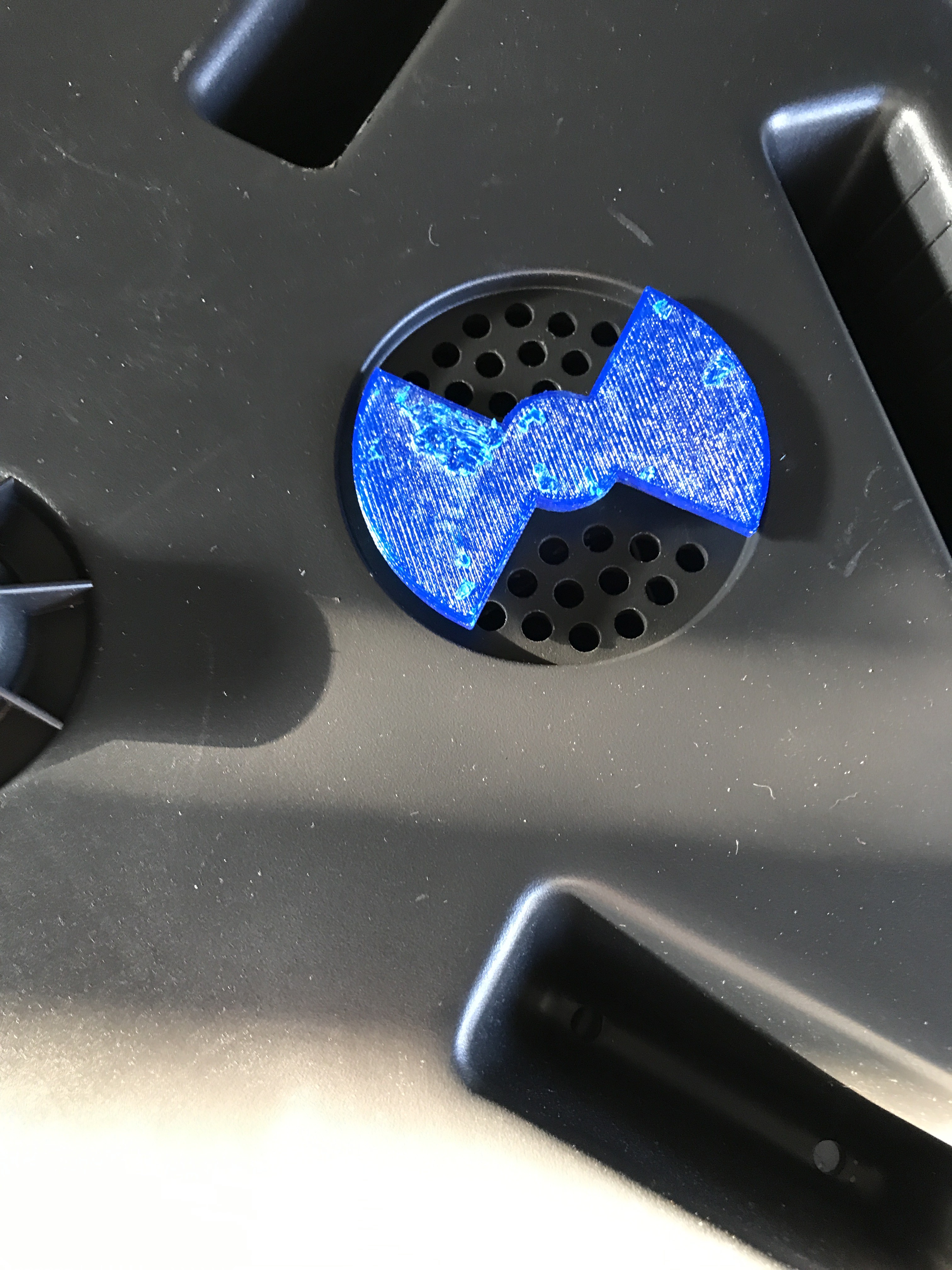
Assemble Automated Air Vent and Attach the Moisture and Temperature Sensors
[Note - for some reason, this step always appears as #1, even after I move it. This step labeled "Ready Moisture and Temperature Sensors for Compost Bin"]
Materials Needed:
Servo and plastic wing
3D Files - Servo Wing, Servo Case, Servo Back
Small Screws (M2.5)
Glue
Assembled moisture probe and temperature probe
Prep
If your compost bin has air and a vent opening, remove the wing. If there are no air holes, you will need to add them after you add install the automated vent
Ensure that the servo cables are covered with heat shrink and are 4-6 feet.
Air Vent Assembly
Insert the servo into the Servo case and attache the back. Glue the case into place.
Position the servo on the inside of the compost bin, in the location where it will control the vent and screw into place.
Glue the Vent wing to the servo horn
Attach the Servo Horn (with the attached wing) to the servo
Install the Moisture and Temperature Sensors
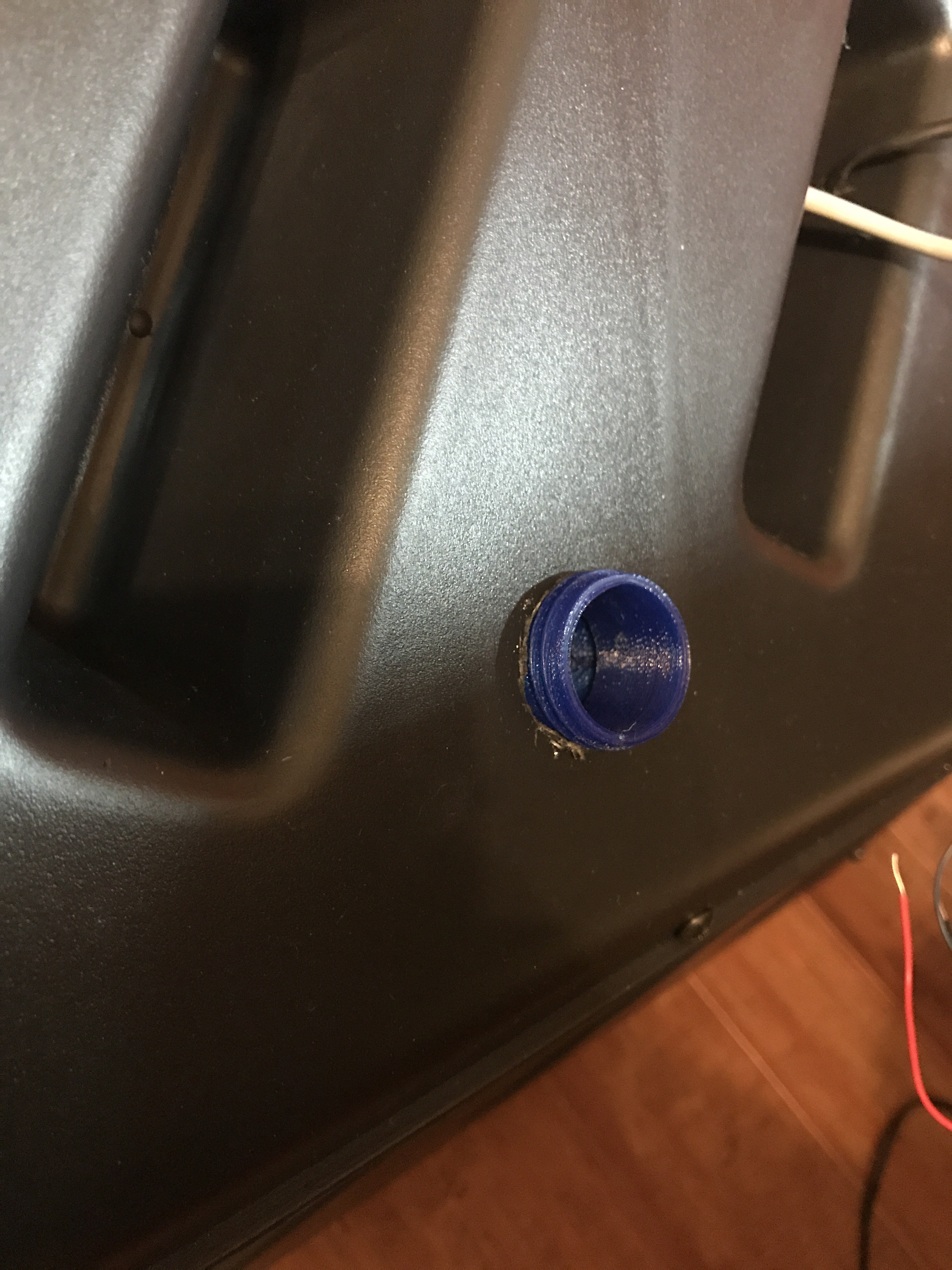
Drill two small holes, about 2 inches apart, into the bottom of the compost bin.
Snake the Temperature Sensor cable from INSIDE to OUTSIDE to INSIDE the compost bin
Use epoxy to secure the Temperate Sensor to the compost bin. The plastic bottle top should be flush against the bin. The Temperature probe should be pointing upward
Repeat the same steps for the Moisture Sensor
Expose all Cables
Once this is complete, use a drill to make holes into the top of the compost bin. Pull all wires through the holes so that they out the outside of the bin at the top.
8
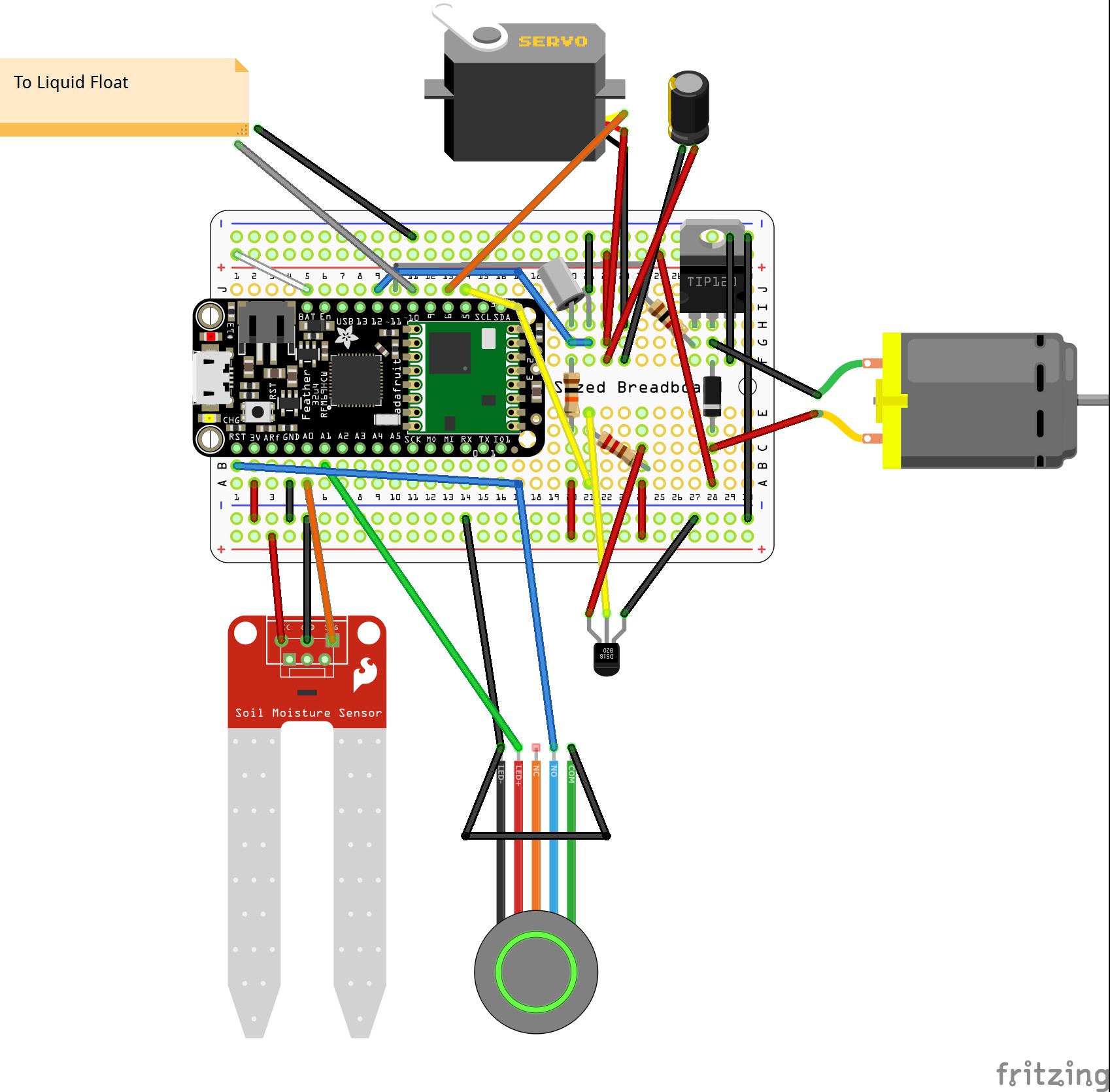
Install code onto the Compost Bin unit microprocessor
Install the Compost_Unit.ino file into the 32u4 RFM69HCW Packet Radio Feather.
Using a breadboard, connect all components to the feather and ensure the code is correct.
Follow the diagram below for wiring.
9
Prep the Electronics Case and Final Assembly
Use a rubber spray coating to water-proof the electronics case - this will take up to 24 hours to cure
Once this is complete, drill 6 holes into the case for the sensors and the battery
Screw the button into the top of the Electronics Case
Solder the 2-pin JST connector to the 3AA waterproof battery case.
Solder all components to the feather (ensuring that the cables are inserted into the case holes before soldering). Ensure that extra cable is shortened to the appropriate length.
Use a small dab of glue to secure the Feather to the bottom of the case.
Attach the top of the case and use silicone and glue to waterproof and secure.
Use epoxy to secure the case to the top of the bin.
10
Build the Base Unit
Component Needed:
Huzzah Feather
RFM69HCW Wing
M2.5 Screws
Base Case and Cover 3D files
Glue
3MM Red/Yellow-Green RGB LED
Tactile button (6mm height)
USB wall charger and USB cable
Steps:
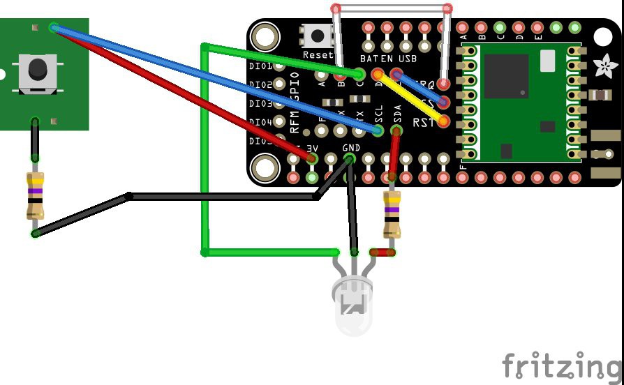
Upload the base_unit.ino file to the Huzzah selected for the Base Unit (this Huzzah will have short stacking headers soldered on, and will use the RFM69 Wing)
Solder the tactile button (reset) and the LED indicator to the RFM69 wing (using the diagram below - NOTE: use stranded wire to make manipulating the wire easier)
Attach the RFM69 wing to the Huzzah and screw the Huzzah into the Base Unit case.
Use a small dab of glue to anchor the LED and Reset Button to the case (note: the reset button will be positioned behind the small pin hole).
Attach the top of the case.
Plug in the unit and connect to the CompostProfessor_XXX wifi network to complete setup.
 Darian Johnson
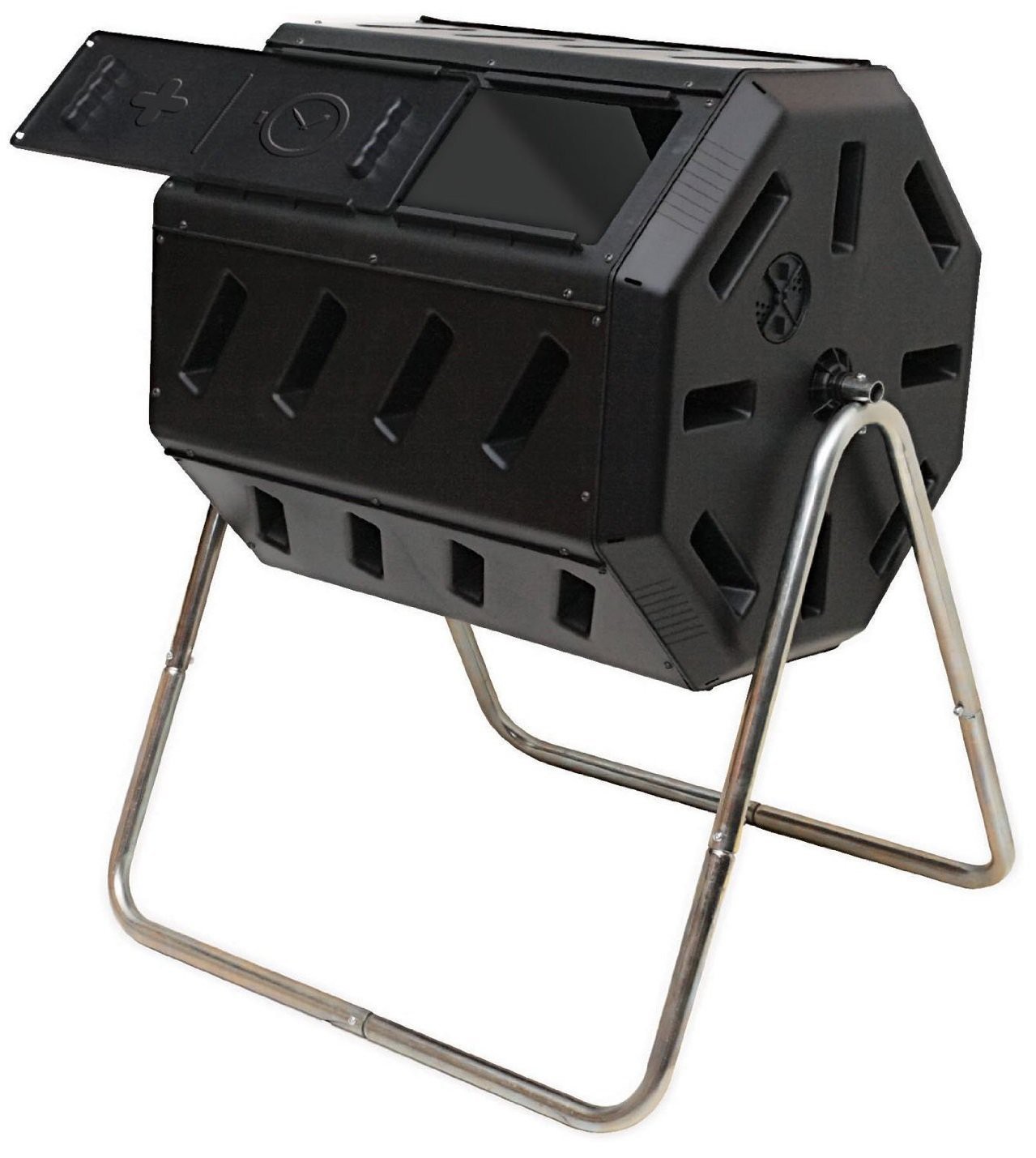


Discussions
Become a Hackaday.io Member
Create an account to leave a comment. Already have an account? Log In.