-
Working on the prototype
08/24/2017 at 21:30 • 0 commentsAfter coming back from vacations (lovely Japan) I'm slowly returning to my daily grind and finally carving time to work on the ZBeam.
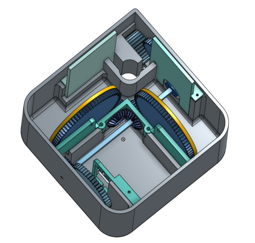
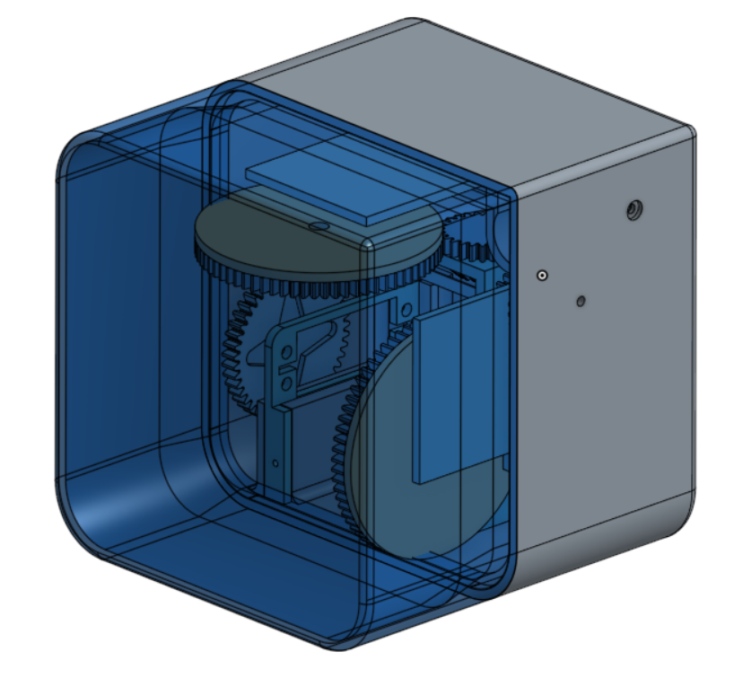
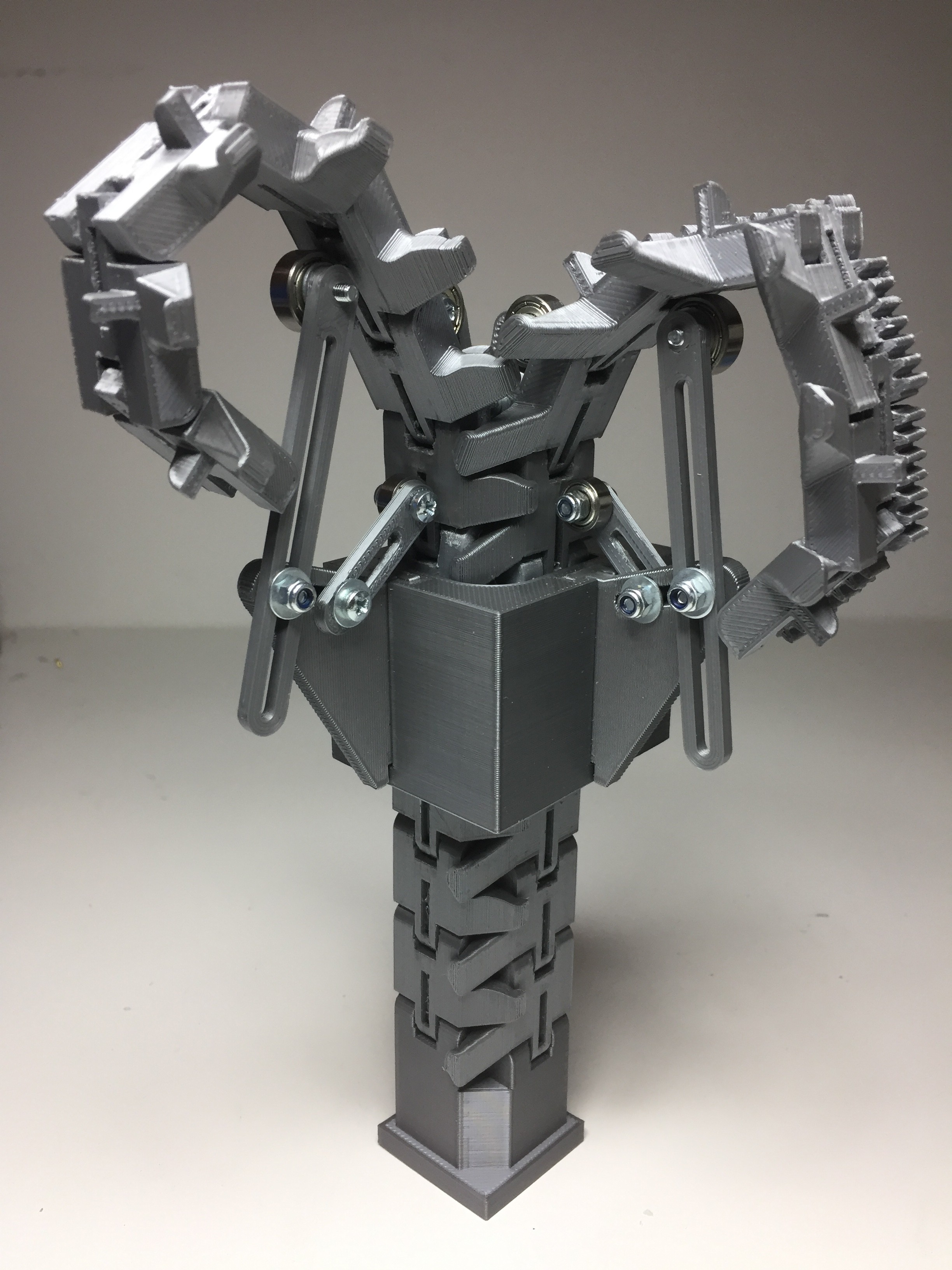
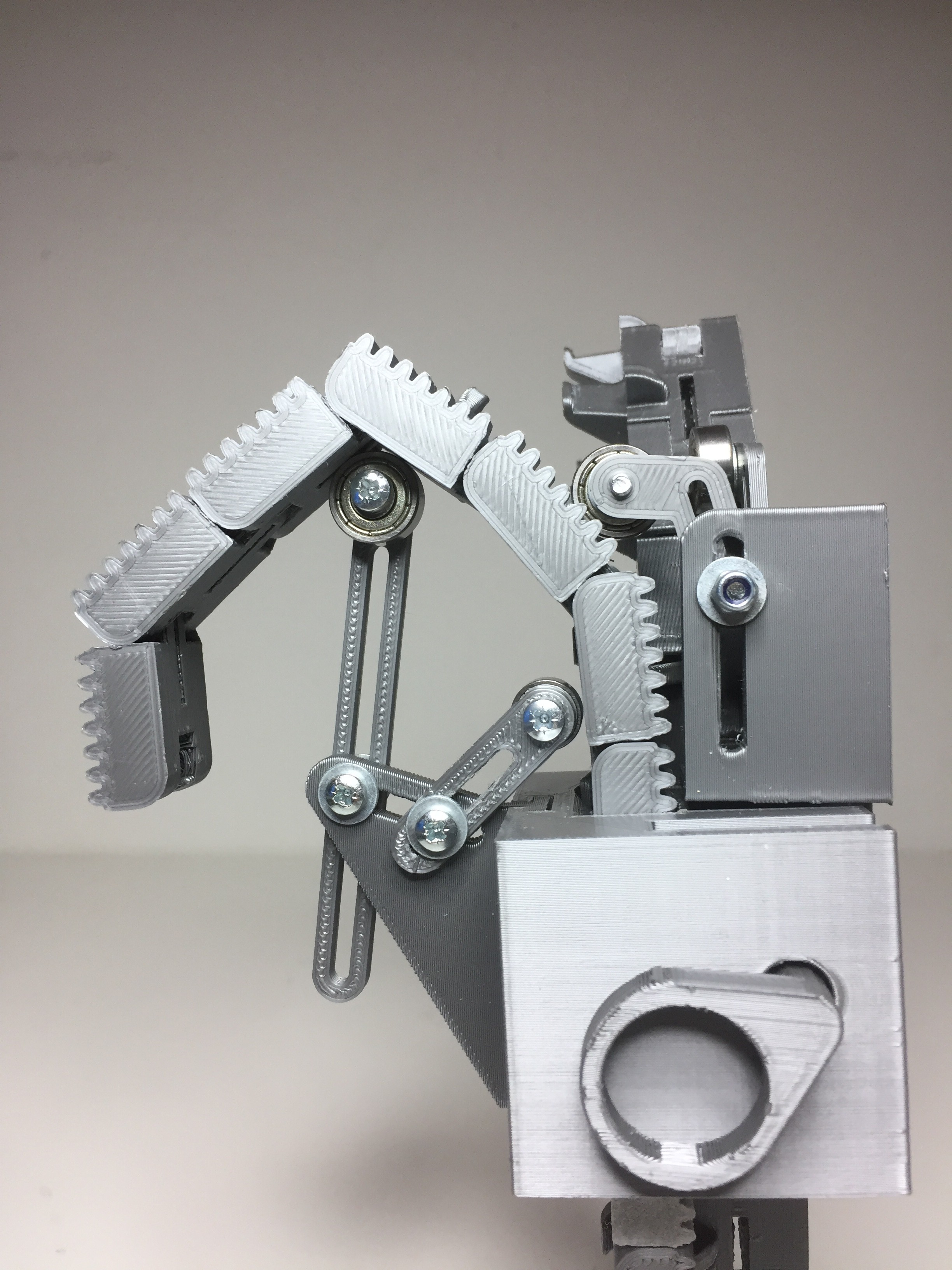
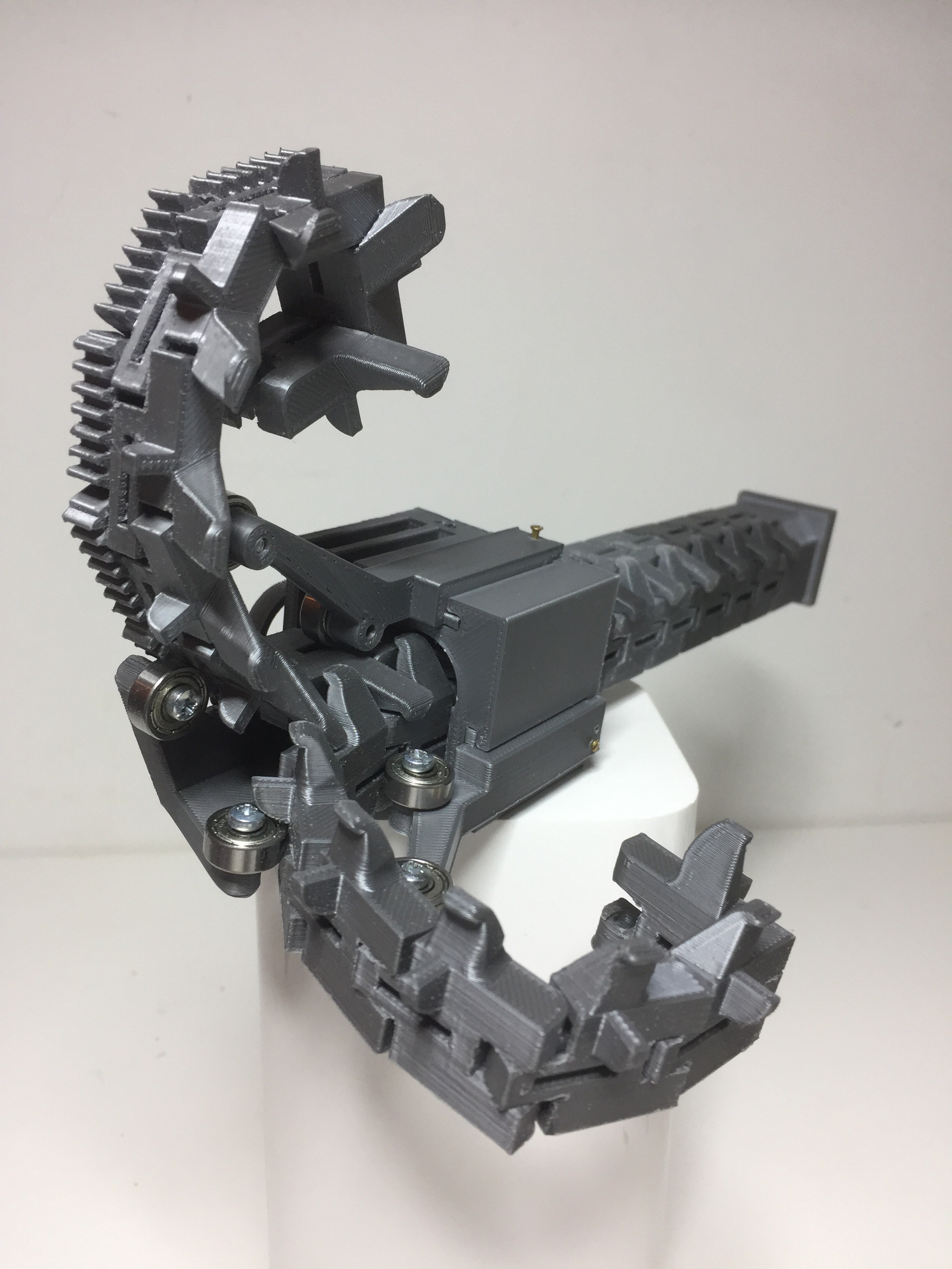
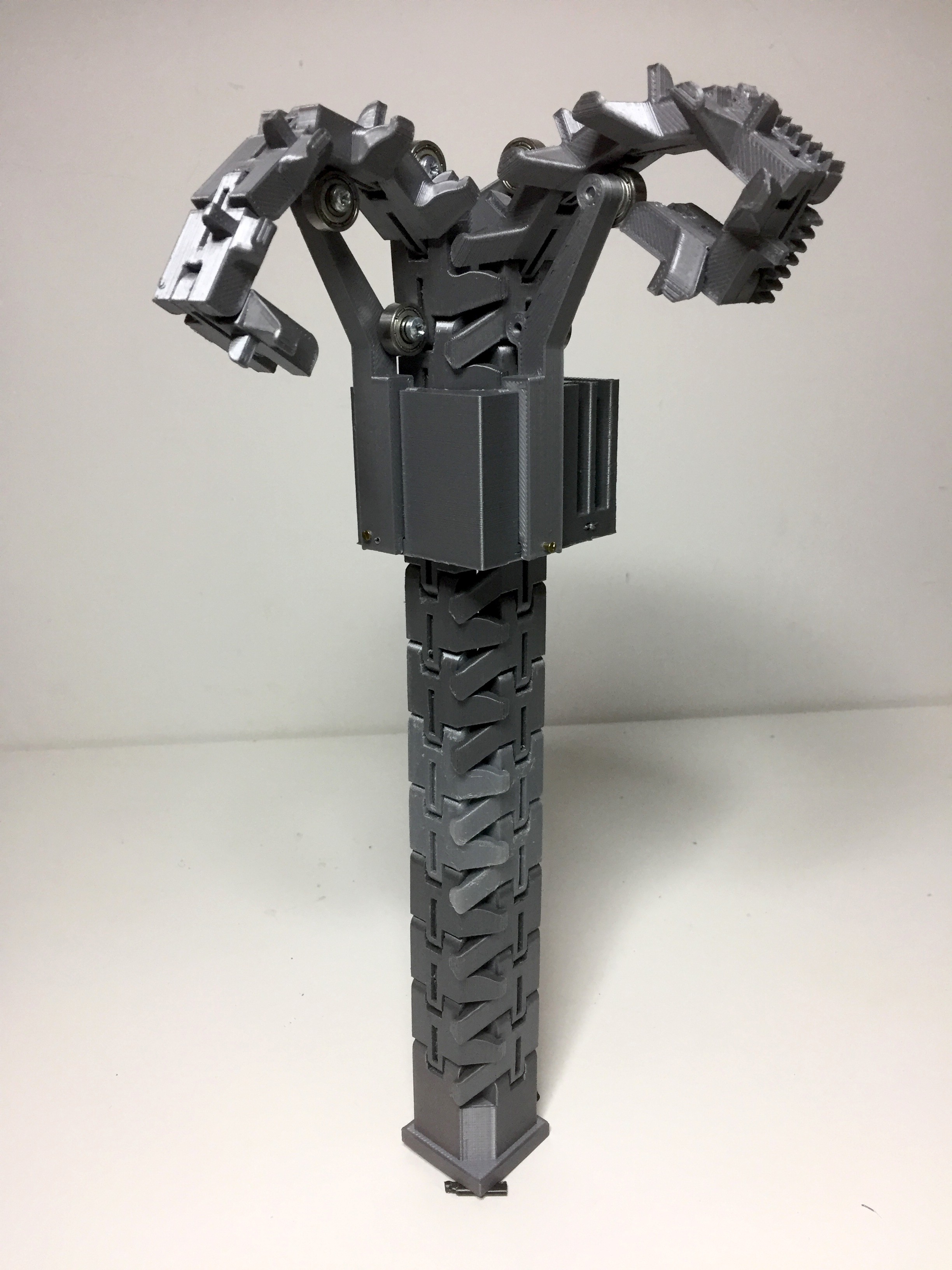
Until now I have develop and tested the individual components of the system, now it's time to integrate everything into a cohesive product prototype.
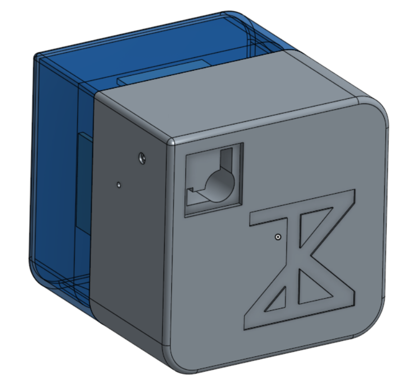
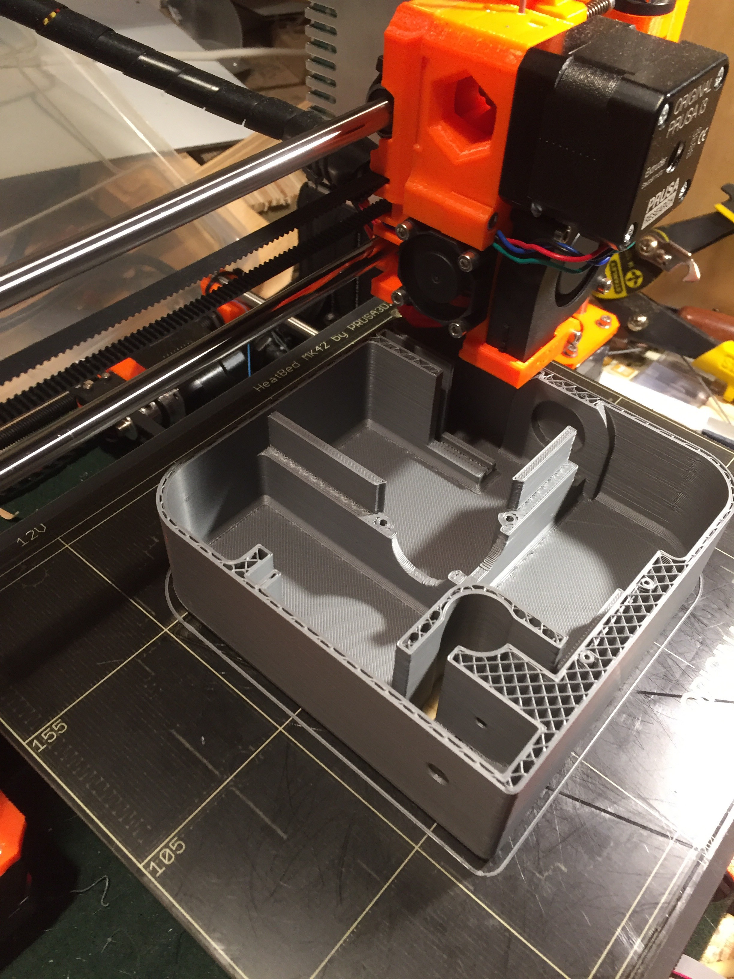
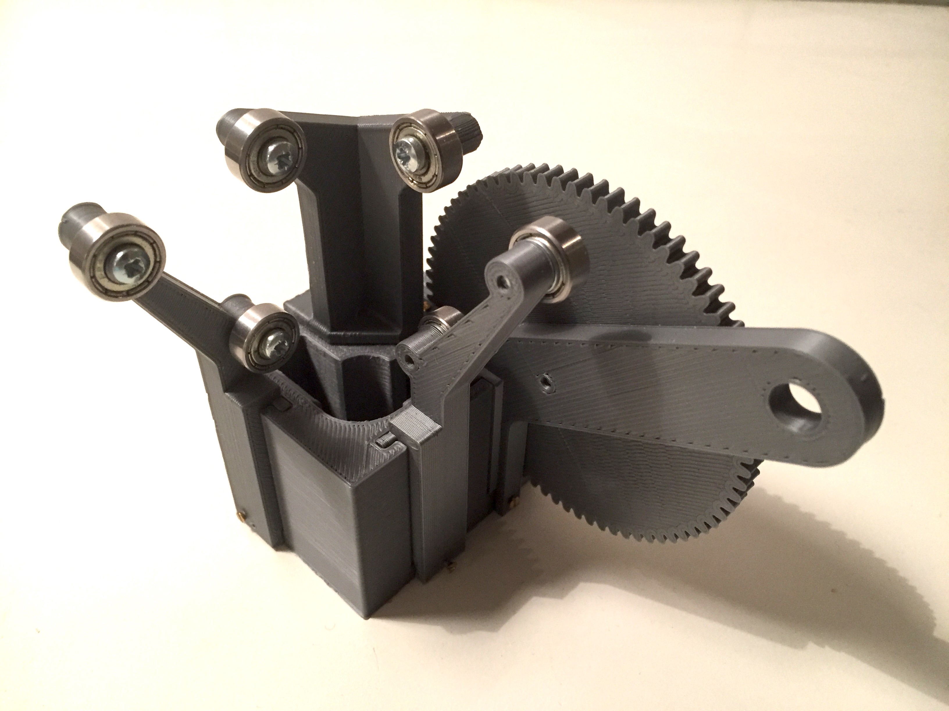
Designing the casing has been a challenging puzzle. I soon realized that due to the resolution constrain of current FDM technology I have to drop my ambition of packing everything into a CubeSat unit size (100x100x100mm), and settle for a larger (135x135x135mm) unit size (until I get my hands on some SLA or SLS printer).
I will be printing a lot this weekend, testing how everything fits together and iterating until I get it right.
![]()
![]()
![]()
![]()
-
Reeling and ratchet gears
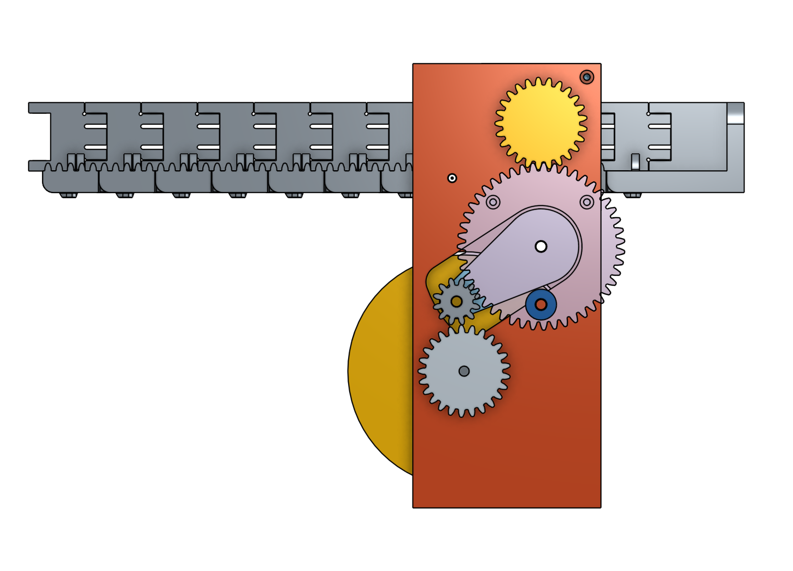
07/09/2017 at 00:09 • 0 commentsReeling the chains in or out has been challenging. It has proven difficult to get the rate at which the beam is interlock/extruded and the rolling to match. I tried first with a design for an active rolling on retrieval, but passive on extrusion based on a smal gear on a floating lever. The gear only engaged when the gear train was driven in one direction.
![]()
In practice once the roll got a certain amount of turns, it was not possible to be "rolled" out just by the extruder pulling on the chain.
So it was back to the drawing board =(
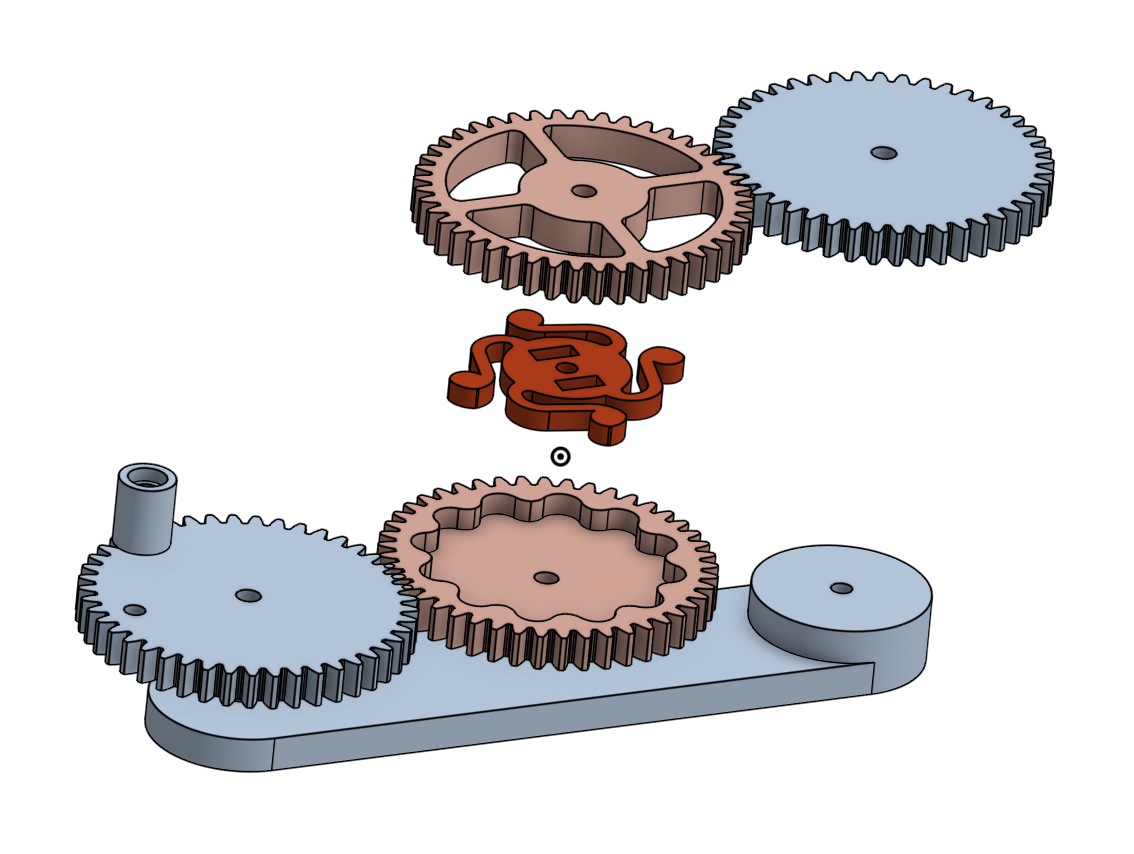
What I needed was a gear with a "safety-ratchet". Instead og jamming I wanted the reel to skip if it was too slow or too fast in relation to the extrusion. This is what I come up with:![]()
On this "safety-ratched gear" he amount of "give" or "grip" can be configured by changing the dimensions on the central spring. I did a number of prints to test the different sizes/geometries until I found one with the right resistance.
I have uploaded the test rig to Pinshape if you want to play with it. You can get the STL there: https://pinshape.com/items/37022. You can edit the CAD to fit your needs using this link to the shared OnShape project: https://cad.onshape.com/documents/f6e...
-
Optimisation of chain segments for print
06/30/2017 at 13:53 • 0 commentsThis iteration was mainly about trying to reduce the time needed to postprocess the link elements after each print. Ideally being able to print chain segments instead of individual links. The current click-snap system was overly complicated, so it was replaced with a simpler one.
![]()
After playing with tolerances I found a sweet spot for my Prusa i3, where a printed chain segment can easily be broken into it's constituent links, but the joints still are solid enough to create a support structure when interlocked.
Being able to print segments is definitively and improvement, but printing complete chains will be even sweeter. So I was thrilled when Printrbot announced their new product, the Printrbelt, an "infinity Z" FDM printer.
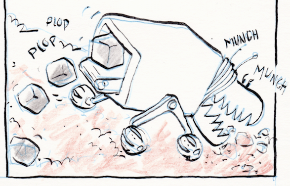
Hopefully we are slowly but surely getting closer to the regolith munching machine I fantasise about.
![]()
-
Actuator test
06/23/2017 at 01:21 • 0 commentsI modelled and printed a crude mount for a TowerPro MG995 servo. I hacked the servo in order to run it continuously. I wanted to test if the torque of the TowerPro was enough to drive a beam horizontally and vertically. It worked nicely =)
The reeling mechanism is a completely different story, I think I'll try a spool system, but I'm leaving it for now. Next step is a new iteration on the links. The requirements are:
- more compact design (for a tighter reel). The current size is 160x160mm. Ideally I want to hit the CubeSat unit size of 100x100x100 and max weight of 1.33kg.
- easier to print. Need to minimise support materials and cleanup
- easier to assembly and disassembly. It should be easy to take the links apart
-
Testing the reeling mechanism
06/20/2017 at 00:49 • 0 commentsI modelled a new part for the slider block, where I could mount a gear train connecting the main driver to the spool holder. I did a quick test after printing the part and the corresponding gears. The part worked ok, but now I need to print more links so I can test with a longer chain. The extra bulk will probably require a longer part, and maybe an update to it's angle for at better alignment with the guides.
Next I need to model the gears needed to connect the other spool.
-
Updates to the slider
06/17/2017 at 01:25 • 0 commentsWith the increased tightening of the chains, the existing slider became quite prone to jamming. To address this I needed to redesign the guide arms. I decided to add bearings as contact points. In order to get the placement of this points right I started by printing an adjustable set of linkages.
After som fidgeting and some trial and error, I was happy with an specify configuration. I redesigned the slider block with a set of (permanent) guiding elements.
Next, i began to work on the spool holder and gear transmission needed to roll the chains.
-
Snap links and improved tolerances
06/10/2017 at 23:59 • 0 commentsThe telescoped beam with the current link design was not as rigid as I wanted. Most of the slack is due to usage of pins or rods for the connection between links. So I redesigned the links to implement a snap-on mechanism instead. This resulted in a much tighter join and a much quicker assembly.
-
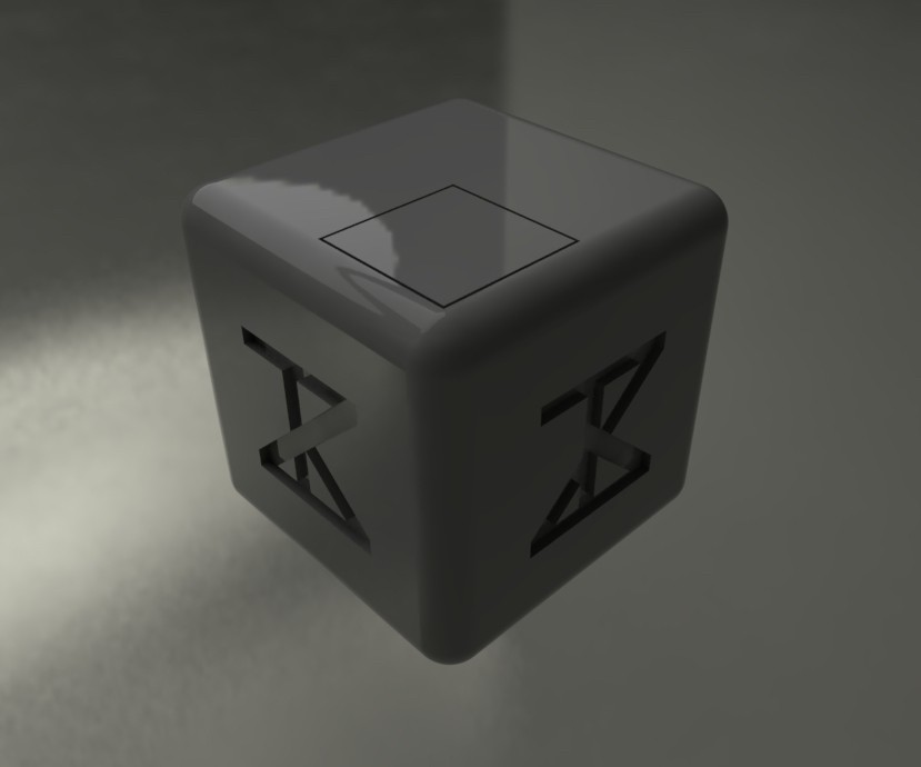
Project identity
06/10/2017 at 00:24 • 0 commentsGot some time today to have some fun with the project branding/identity. One of the requirements for the design was that it should look cool when embossed on the side of the units =)
![]()
![]()
And here is a rendering of a ZBeam unit with the logo embossed:
![]()
-
Working on the reels
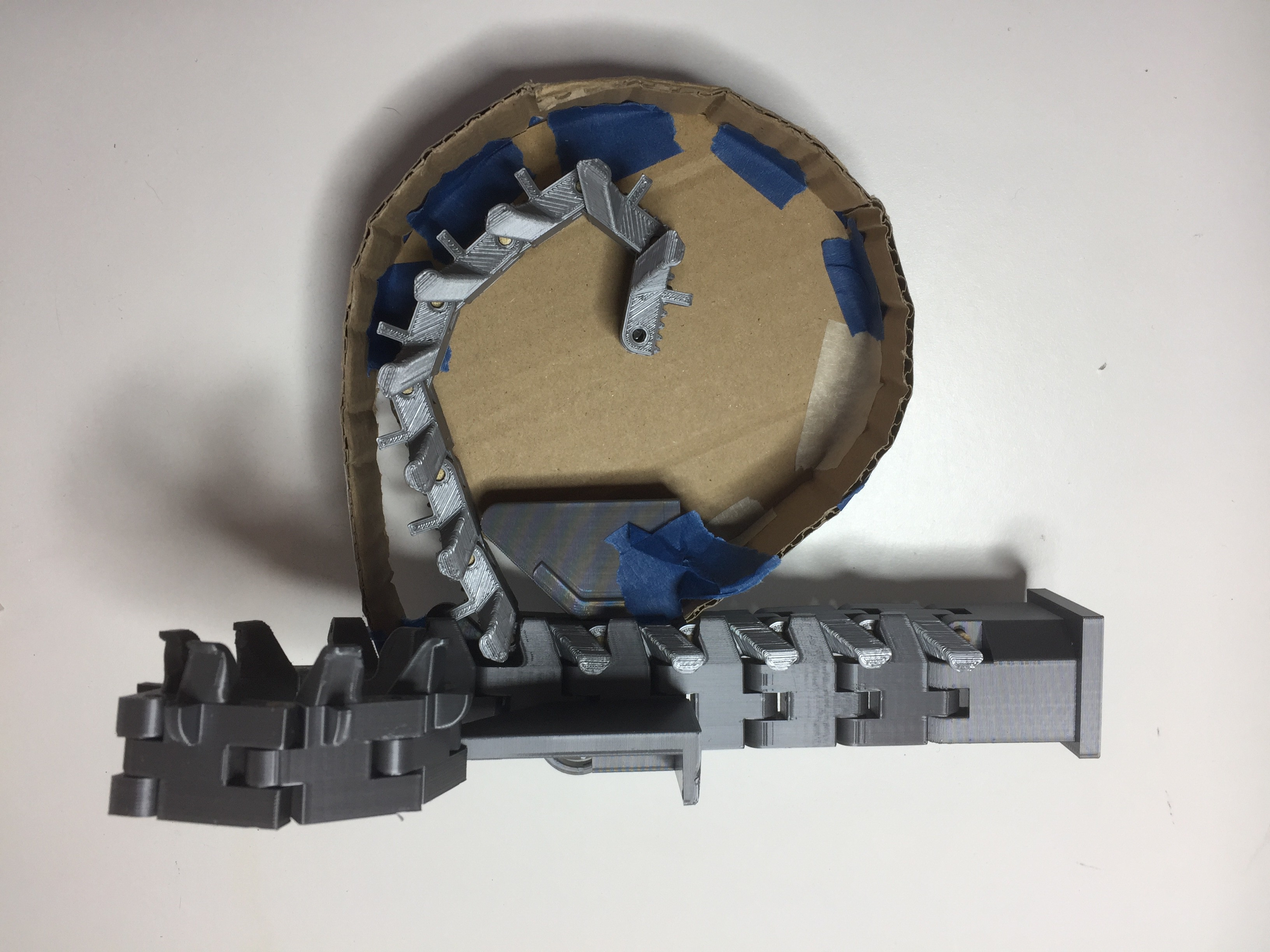
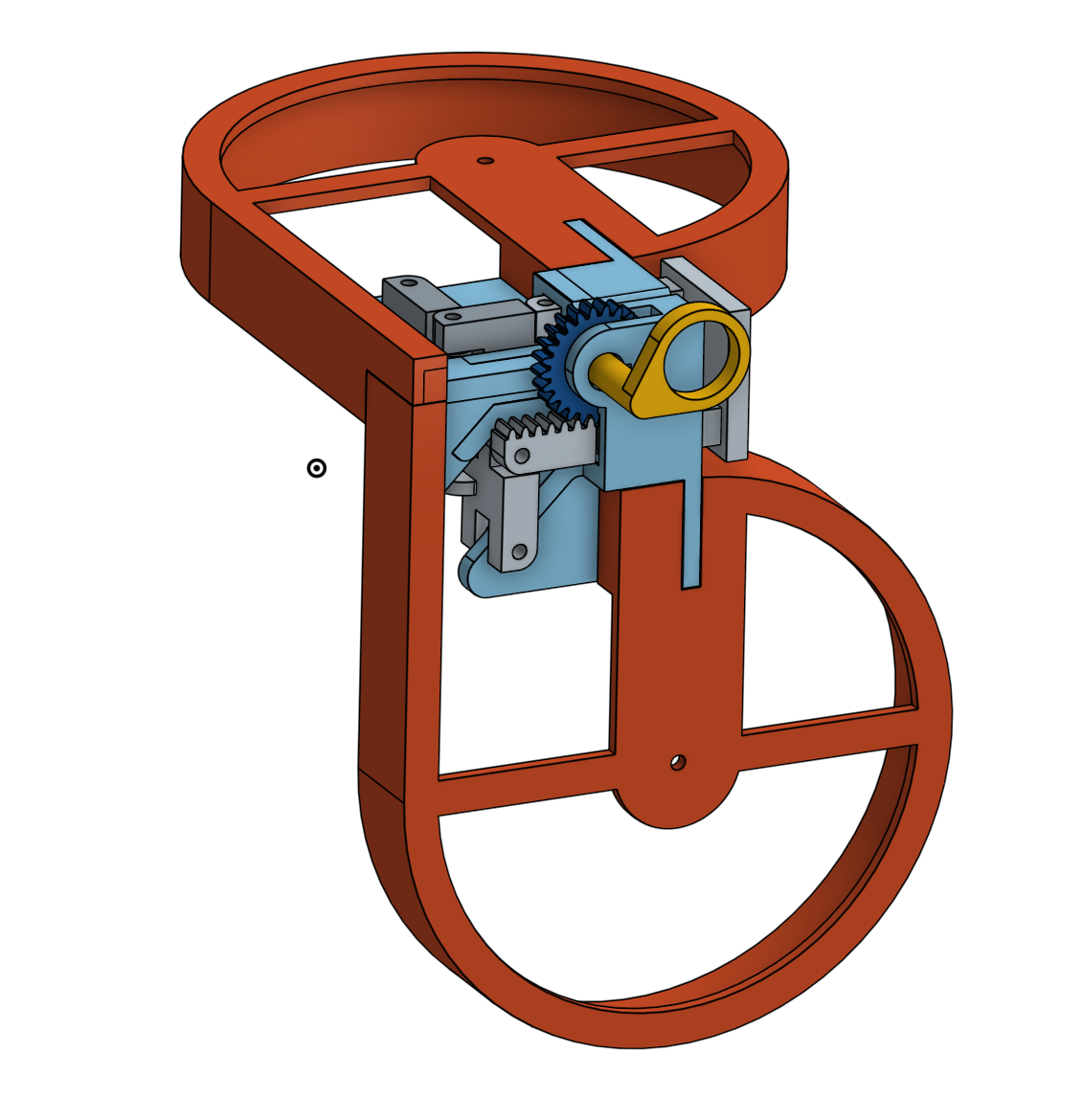
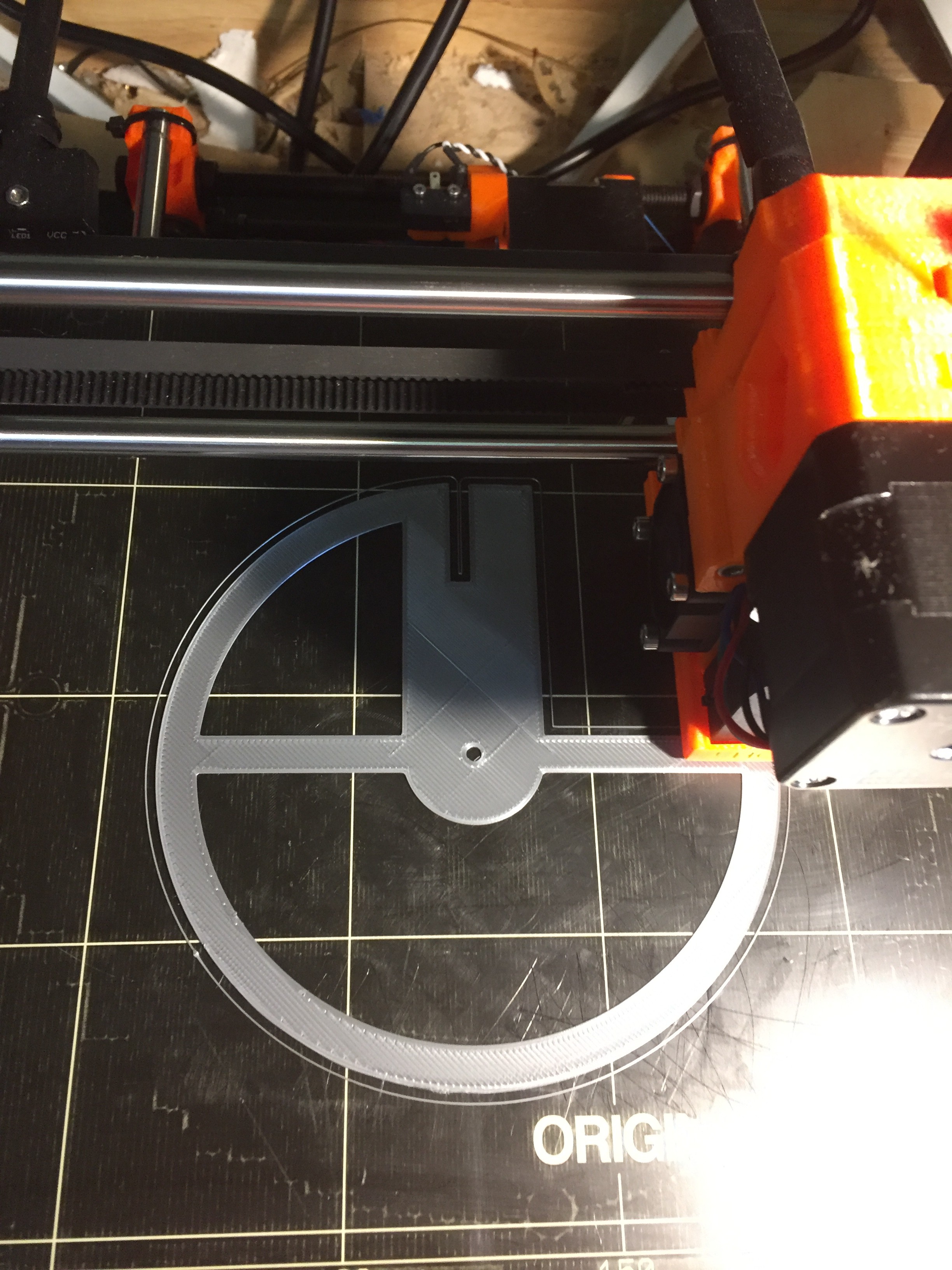
06/05/2017 at 16:27 • 0 commentsI need a way to manage the rolled links, so I start working on a pair of reels. Started with a kick prototype with cardboard and tape to test the size/geometry.
It worked ok, so I modelled it in OnShape.
![]()
...and sended the parts to my trusty Prusa...
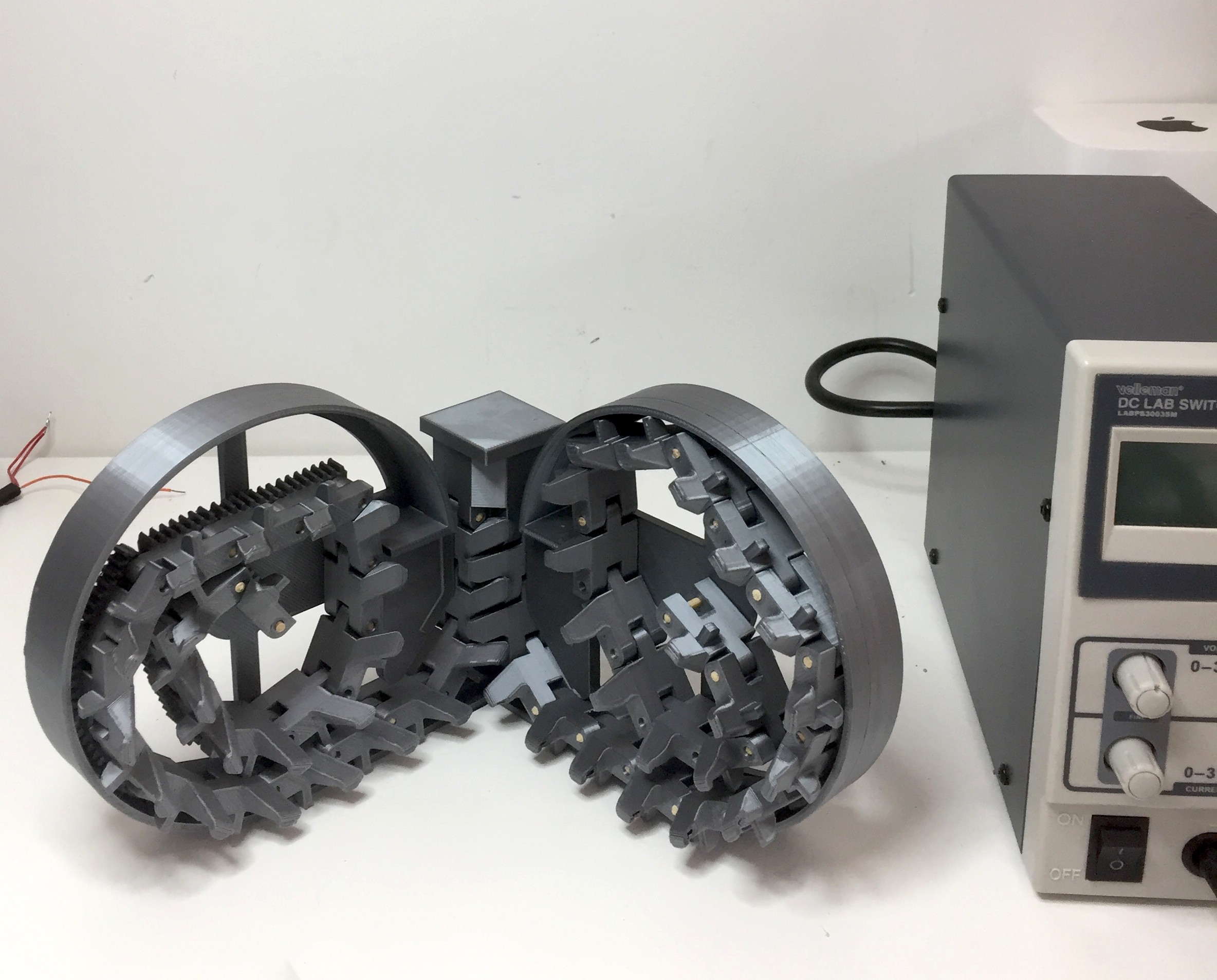
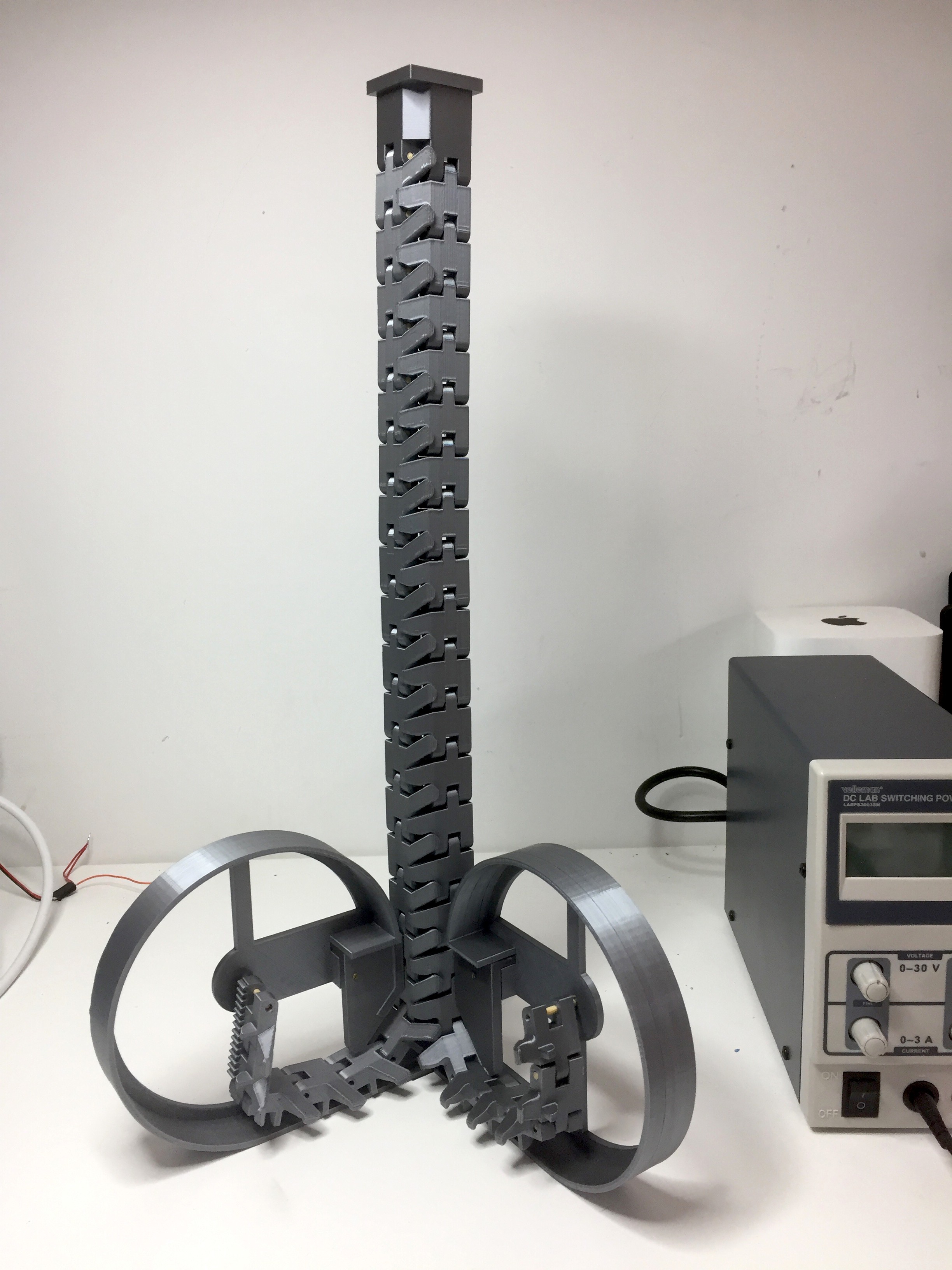
This morning I harvested the parts and was able to mount and test the reels. The power supply is just for size reference.
This sort of worked. I need to connect the main drive to the reels to help rolling the chains in and out, otherwise they will jam in different positions/orientations.
And before you add any funny comments, this is not the final form-factor. The reels will be enclosed in a cube, that may contains four reels, eg. two beams per cube.
-
Small geometry updates to the links
06/04/2017 at 19:09 • 0 commentsI had to do somme trimming of the link geometry in order to get a consistent meshing. The parts are interlocking much easier now. Once I'm done with this first iteration I need to go back and clean/redo my CAD. It's really messy!
I use OnShape, so it will be easy to share the files and to check the project directly from any browser.
![]()
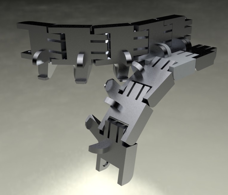
I think the links look like they are pals holding each other =)
ZBeam - Shape Shifting Structures For Space
Self-reconfiguring modular structural elements for space habitats
 Ronald Jaramillo