 Bud Bennett
Please Don't Like or Follow This Project -- There is a newer/better version: The Ultimate Single Cell Lithium UPS for Raspberry PI (U1LiUPSRPi). Check it out.
I started out trying to modify the super capacitor UPS system, but it quickly became apparent that was not the right approach -- too many components and too many constraints that did not apply to the Li-Ion case. I enlisted PaulV as co-conspirator and together we were able to reduce the solution into a pretty small, but effective, package.
This is what the UPS must do:
- Provide power to the output ( the Pi power input) when external power is lost by drawing from the battery source.
- Let the Pi know that this has occurred, so that it can do a proper shutdown at an appropriate time before the battery is exhausted.
- Accept a shutdown command from the Pi and handshake to confirm the shutdown command was received, and after shutdown is complete, switch the Pi off by disconnecting the power.
- Reconnect the power to the Pi, which causes the Pi to boot, when the external power returns.
Functional Overview:
The basic organization of any UPS is shown in the following diagram.
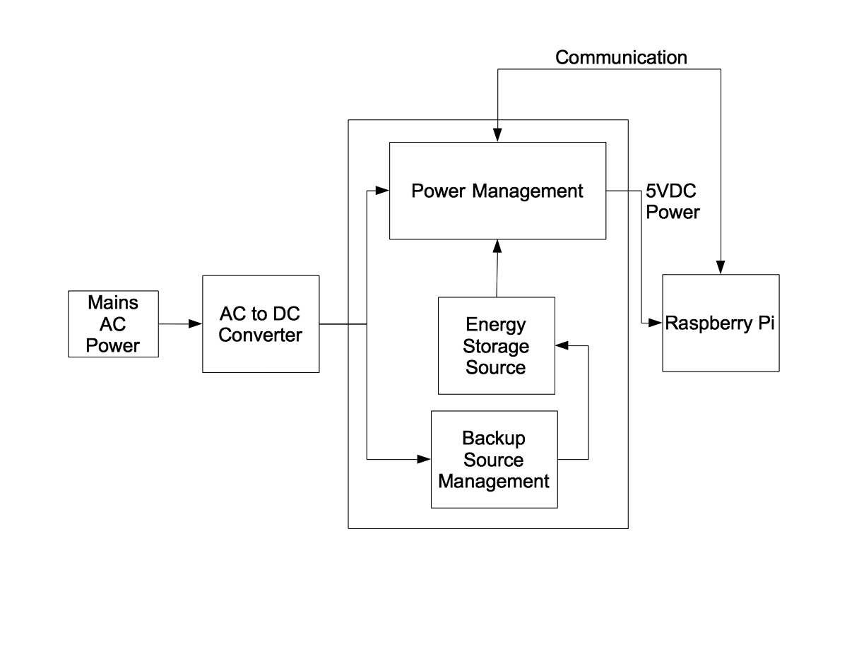
The AC-DC converter can output almost any voltage, but it is usually a voltage larger than the required input voltage of the load (the Raspberry Pi). Many UPS systems use 12VDC or 24VDC and then use a step down, or buck converter, (or heaven forbid…linear regulator) to produce the required 5VDC output to the RPi. If the AC power fails, the Power Management block automatically switches over to the the stored energy source to keep providing power to the load. There are lots of variations on this theme, but the usual method is to have a switch mode converter that provides a constant 5VDC output and switch its input between the AC-DC converter output and the Energy Storage by using a simple diode selector. So what you have during normal operation is a cascade of switch mode converters, each with its attendant power loss and noise generation due to the switching action.
This UPS is a bit different than most others. Here’s the block diagram:
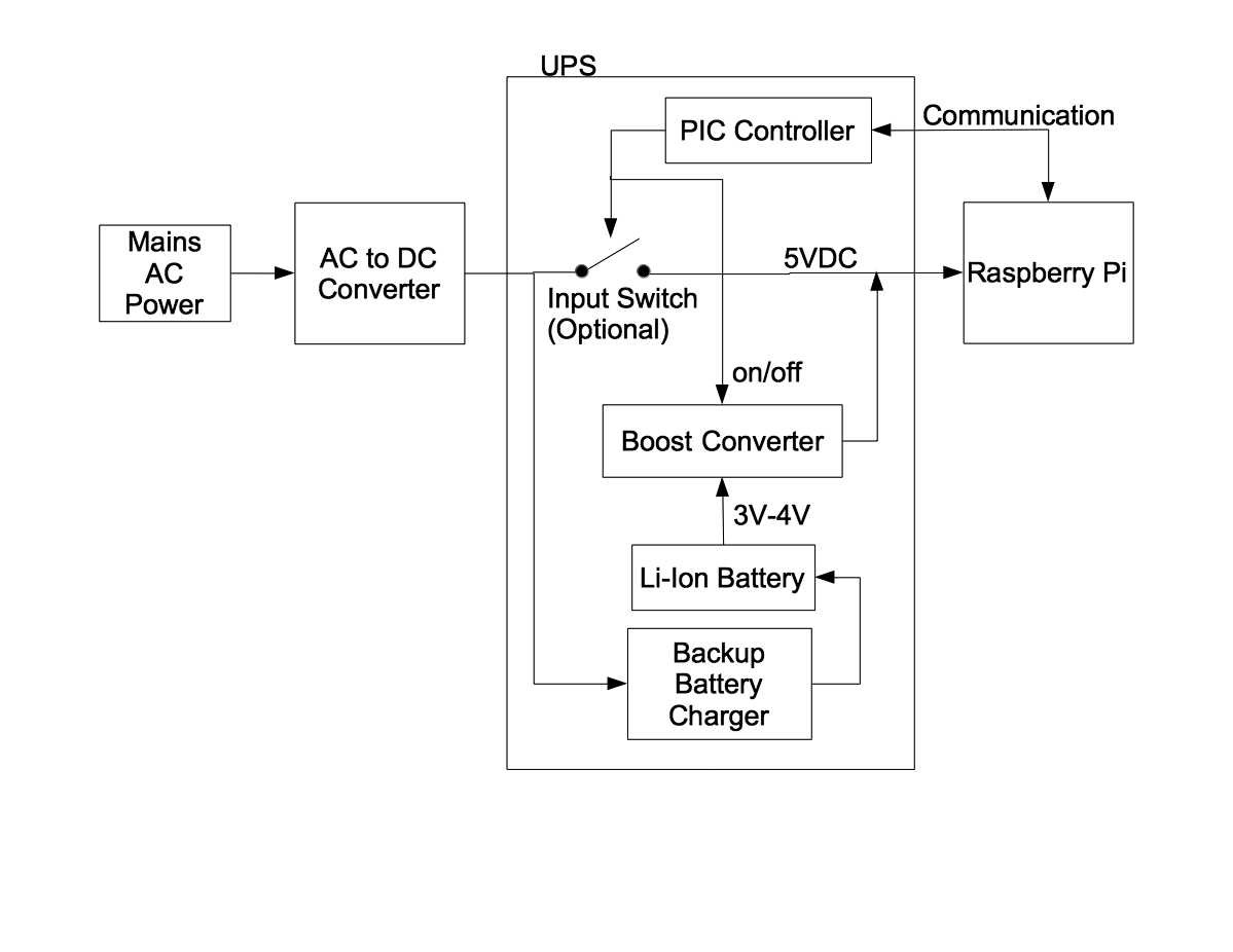
The AC-DC converter (the wall wart) outputs slightly more than 5VDC, say 5.15-5.25V, which is at the top end of the acceptable voltage range of the RPi. It is connected to the UPS output at all times — even when there is no AC power. The Energy Storage source is a single-cell Li-Ion battery with a typical voltage range of 3V to 4.2V and requires a boost converter to convert the battery voltage to the 5VDC required at the output. The boost converter is also connected to the output at all times but has its target output voltage set slightly below the wall wart output voltage. There is no diode selector because the boost converter manages the power switchover event at the UPS output. When the wall wart is providing power the UPS output voltage is held above the boost converter target voltage so the boost converter is inhibited from switching. When the AC power fails the wall wart simply changes state and becomes a relatively high impedance (something between 1megΩ and 500Ω, which is not much of a load). As the UPS output voltage falls below the boost converter target voltage it begins to switch and takes over providing power to the output. This switchover event needs to happen quickly in order to prevent any glitch from disrupting power to the load.
There are several advantages to this approach. It is inherently low power and low noise when operating on AC power (ignoring the required wall wart losses). The only power loss is some small overhead in the associated management system — about 500µA, or 2.5mW. The booster doesn’t make any noise if it’s not switching. It is low complexity, but the boost converter requires a bit of care to prevent any significant glitches at the output.
Index of Logs:
I have had a complaint that it is difficult to find information in the log files. Therefore I'm including a log index with a brief explanation of contents....
Read more »

 Kumar, Abhishek
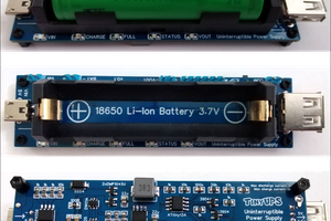
 Stefan Wagner
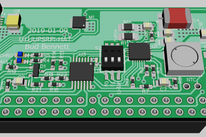

 Jack Steiger
The reason I wanted to try and get 3Amps out of the UPS is that my intended target is an RPi Model 3.
The power requirements for this model are such that most UPS systems cannot reliably satisfy the demands when you have an intensive use of the 4 cores, and some devices hanging off the USB ports.
Most of the "other" UPS systems we looked at that are available for the Model 3, even commercially, make claims that are hard to believe. The constraints on a battery cell supplying enough current to allow the dwindling cell voltage to be boosted to 5V at 3Amps are beyond most of these designs. Consider that the cell must be able to supply about double the current the RPi needs, so we're talking about a 6Amps + discharge rate. Most 14500 cells cannot do more than 2.5Amps
With those demands, the UPS design takes on another dimension, which is why Bud went through great pains, and many designs and board turns to get it right, we hope.
With these kind of demands on the UPS, you can only expect to get several minutes of cell life and so you cannot really expect a real UPS behaviour. At a minimum, you get a safe power down in case of a mains malfunction. At best you can ride through a short brown out, or a wall wart switch over. This is fine for my application, where my Model 3 is sitting on my desk while I do developments and run tests on it.
The proof is in the pudding and so we're anxiously waiting for the 14500 "Hat" design to arrive.