Bud Bennett
-
Final Python Code...we're finished.
09/10/2017 at 19:43 • 0 commentsThis is (hopefully) the last log. The project is complete at this point.
There are some bits of code that is necessary to get the UPS working properly. Paul Versteeg upgraded the code to include a logging capability and also provided a service file for systemd so it runs nicely in the background.
UPS_POWERFAIL.PY
#!/usr/bin/python3
#-------------------------------------------------------------------------------
# Name:        ups_powerfail.py
# Purpose:
#
# Author:      Bud Bennett (modified by Paul Versteeg)
#
# Created:     31-08-2017
# Copyright:   (c) Bud Bennett 2017
# Licence:     <your licence>
#-------------------------------------------------------------------------------


'''
This program monitors the status of the UPS via the i2c interface and
manages the Raspberry Pi shutdown when the UPS signals that the battery
is exhausted. It lets the UPS determine when the battery is exhausted.
If the UPS battery voltage (VBAT) is greater than 3.2V, the status is checked
every minute. If VBAT < 3.2V then the checking interval is shortened to 1 second.
When the UPS asserts BATLOW = 1, the UPS will wait 5 seconds for the Raspberry Pi
to acknowledge by setting the SHUTDN bit. If the Pi sets SHUTDN = 1 then the UPS immediately
begins a 20 second timer to terminate the power. If the Pi has not set the SHUTDN bit
within the 5 second period then the UPS begins the 20 second timer irregardless.
So the Pi must initiate it's shutdown sequence immediately after receiving the BATLOW
signal from the UPS and sending/confirming the SHUTDN acknowledgement. The Pi can also
shutdown the UPS at any time by sending the Shutdown Command (0x04) to the UPS.
'''

try:
    from smbus import SMBus
except ImportError as e:
    print("Python module smbus not found, install it first")
    # Install the i2c interface using the following instructions:
    # sudo apt-get install i2c-tools
    # sudo apt-get install python-smbus
    # sudo raspi-config , goto Interfacing Options, enable i2c
    # sudo reboot # to make the i2c interface active
    # now check to see if the USB i2c device is present at address 36
    # sudo i2cdetect -y 1
    sys.exit(0)

import time, os
from datetime import datetime
import logging
import logging.handlers
import traceback
import sys

# Global flag to print more information
DEBUG = True
# If this script is installed as a Daemon by systemd, set this flag to True:
DAEMON = True # do not send stuff to the console

i2c = SMBus(1)  # set interface to i2c-1 (newer RPi's)
ups_address = 0x36
command = 0x00
VBAT = 5
bus_fail = 0
pgood_flag = 1


#--logger definitions
# save daily logs for 7 days
LOG_FILENAME = "path-to-ups_mon.log"  # log file path
LOG_LEVEL = logging.INFO  # Could be e.g. "TRACE", "ERROR", "" or "WARNING"
logger = logging.getLogger(__name__)
logger.setLevel(LOG_LEVEL)
handler = logging.handlers.TimedRotatingFileHandler(LOG_FILENAME, when="midnight", backupCount=7)
formatter = logging.Formatter('%(asctime)s %(levelname)-8s %(message)s')
handler.setFormatter(formatter)
logger.addHandler(handler)


def  write_log(mode, msg=""):
    '''
    Create a log file with information during the running of this app.
    Log information with a qualifier to easier sort it.

    '''

    if mode == "info" or mode == "message" or mode == "trace" :
        logger.info(msg)
        return

    if mode == "debug" :
        logger.debug(msg)
        return

    if mode == "error" :
        logger.error(msg)
        return

    if mode == "warning" :
        logger.warning(msg)
        return

    if mode == "critical" or mode == "exception" :
        logger.critical(msg)
        return
    # catch all
    if (DEBUG) and (not DAEMON) : print( "---catch all---"), mode
    logger.critical(msg)
    return


def read_ups_data(address=0x36, cmd=0x00):

    bus_fail = 0

    if (DEBUG) and (not DAEMON) : print('Sending command {0:02x}'.format(command))
    # write_log("trace", "Sending command {0:02x}".format(command))

    try:
        word = i2c.read_word_data(ups_address, command)
    except Exception as e: # except all exceptions

        if (DEBUG) and (not DAEMON): print('I2C exception')
        write_log("error", "read_ups: I2C exception")
        bus_fail = 1

    if bus_fail == 1:
        VBAT = 5.0
        BATLOW = 0
        SHUTDN = 0
        PWRGOOD = 1
    else:
        byte1 = 255 & word
        byte2 = word >> 8
        PWRGOOD = byte1 & 0x01
        BATLOW = (byte1 & 0x02) >> 1
        SHUTDN = (byte1 & 0x04) >> 2
        if byte2 != 0:
            VBAT = 2.048/byte2 * 255
        else:
            VBAT = 5.0
            if (DEBUG) and (not DAEMON): print('read_ups: ADC value error')
            write_log("error", "ADC value error")
        bus_fail = 0


    if (DEBUG) and (not DAEMON):
        print('PWRGOOD = {0}'.format(int(PWRGOOD)))
        print('BATLOW = {0}'.format(int(BATLOW)))
        print('SHUTDN = {0}'.format(int(SHUTDN)))
        print('VBAT = {0:.2f}\n'.format(VBAT))

    return PWRGOOD, BATLOW, SHUTDN, VBAT, bus_fail


def main():
    global command, pgood_flag

    time_now = datetime.now()
    if (DEBUG) and (not DAEMON) : print("{0} Powerfail is active.".format(time_now))
    write_log("trace","*** Powerfail is active")

    try:
        while True:
            # read the UPS
            PWRGOOD, BATLOW, SHUTDN, VBAT, bus_fail = read_ups_data(ups_address, cmd=command)

            # de-clutter log -- only send powerfail info once
            if (not PWRGOOD and pgood_flag):
                   time_now = datetime.now()
                   pgood_flag = 0
                   if (DEBUG) and (not DAEMON) : print("{0} Powerfail: Power failed.".format(time_now))
                   write_log("trace", "Power failed: PWRGOOD = {0} BATLOW = {1} SHUTDN = {2} VBAT = {3:.2f}".format(PWRGOOD, BATLOW, SHUTDN, VBAT))
            elif(PWRGOOD and not pgood_flag):
                   time_now = datetime.now()
                   pgood_flag = 1
                   if (DEBUG) and (not DAEMON) : print("{0} Powerfail: Power restored.".format(time_now))
                   write_log("trace", "Power restored: PWRGOOD = {0} BATLOW = {1} SHUTDN = {2} VBAT = {3:.2f}".format(PWRGOOD, BATLOW, SHUTDN, VBAT))

            # if the UPS has set BATLOW or VBAT < 3V, then send SHUTDN command to initiate UPS shutdown
            if (BATLOW or (VBAT < 3.0 and not PWRGOOD)):
                if (DEBUG) and (not DAEMON) : print('Powerfail: Sending shutdown command.')
                write_log("trace", "Sending shutdown command to UPS: PWRGOOD = {0} BATLOW = {1} SHUTDN = {2} VBAT = {3:.2f}".format(PWRGOOD, BATLOW, SHUTDN, VBAT))
                command = 0x04
                PWRGOOD, BATLOW, SHUTDN, VBAT, bus_fail = read_ups_data(ups_address, cmd=command)

            # confirm that the UPS received the shutdown command and then shutdown the Pi
            if (SHUTDN and command == 0x04):
                if (DEBUG) and (not DAEMON) : print('UPS confirmed, shutting down now!')
                write_log("trace", "UPS confirmed, shutting down now!")
                os.system("sudo shutdown -h now")
                while True:
                    time.sleep(10)

            # check UPS status at 1 minute intervals until battery voltage drops below 3.2V, then
            # decrease interval to 1 second.

            if (VBAT < 3.2):
                time.sleep(1)
            else:
                time.sleep(60) # use 10 seconds during testing, 60 when running normally

    except KeyboardInterrupt:
        if (DEBUG) and (not DAEMON): print ("\nCtrl-C Terminating")

    except Exception as e:
        sys.stderr.write("Got exception: %s" % e)
        if (DEBUG) and (not DAEMON): print(traceback.format_exc())
        write_log("exception", str(traceback.format_exc()))
        os._exit(1)

if __name__ == '__main__':
    main()
ups_powerfail.service File:
# This service installs a python script that communicates with the UPS hardware.
# It also provides logging to a file
# the ups_powerfail.service is located in /lib/systemd/system/
# To test, use sudo systemctl start|stop|status powerfail
# To install during the boot process, use: sudo systemctl enable ups_powerfail
# If this file gets changed, use: sudo systemctl daemon-reload
# If the Python script is changed, use : sudo systemctl restart ups_powerfail

[Unit]
Description=UPS Powerfail Service
Requires=basic.target
After=multi-user.target

[Service]
ExecStart=/usr/bin/python path-to-ups_powerfail.py
Restart=on-failure
RestartSec=10
TimeoutSec=10

# The number of times the service is restarted within a time period can be set
# If that condition is met, the RPi can be rebooted
# WARNING:
# Only use these options with a working system!
#StartLimitBurst=4
#StartLimitInterval=180s
# actions can be none|reboot|reboot-force|reboot-immidiate
#StartLimitAction=reboot

# The following are defined the /etc/systemd/system.conf file and are
# global for all services
#
#DefaultTimeoutStartSec=90s
#DefaultTimeoutStopSec=90s
#
# They can also be set on a per process here:
# if they are not defined here, they fall back to the system.conf values
#TimeoutStartSec=2s
#TimeoutStopSec=2s

[Install]
WantedBy=multi-user.target
I ran several power failure cycles on my Raspberry Pi Model B, with the Raspbian sketch OS installed, a few days ago. This is the output of the log file.
Log Output:
2017-09-07 16:55:43,089 INFO *** Powerfail is active
2017-09-07 16:56:43,153 INFO Power failed: PWRGOOD = 0 BATLOW = 0 SHUTDN = 0 VBAT = 3.55
2017-09-07 16:59:43,288 INFO Power restored: PWRGOOD = 1 BATLOW = 0 SHUTDN = 0 VBAT = 3.68
2017-09-07 17:00:43,301 INFO Power failed: PWRGOOD = 0 BATLOW = 0 SHUTDN = 0 VBAT = 3.53
2017-09-07 17:12:07,007 INFO Sending shutdown command to UPS: PWRGOOD = 0 BATLOW = 0 SHUTDN = 0 VBAT = 2.98
2017-09-07 17:12:07,009 INFO UPS confirmed, shutting down now!
2017-09-07 17:14:14,191 INFO *** Powerfail is active
2017-09-07 22:06:27,317 INFO Power failed: PWRGOOD = 0 BATLOW = 0 SHUTDN = 0 VBAT = 4.08
2017-09-07 23:30:32,978 INFO Sending shutdown command to UPS: PWRGOOD = 0 BATLOW = 0 SHUTDN = 0 VBAT = 2.98
2017-09-07 23:30:32,980 INFO UPS confirmed, shutting down now!FIN.
-
Testing the 14500 HAT-like UPS supply with high current demands
09/10/2017 at 14:55 • 0 commentsFirst of all, let me clarify that with normal 14500 cells in general, a heavily loaded (with attached USB devices) or tasked (running all cores to the max) Raspberry Pi Model 3 will not run for long on these cells, if at all. Regardless of the capacity (between 700 to 900 mAh) available for these cells, they cannot supply the required current levels.
I measured that with these standard cells, the cell voltage will collapse within seconds with currents approaching 1.5A, which is no good for a Model 3.
However, there are 14500 type high discharge capacity cells available. These so called IMR (Lithium manganese oxide, also called LMO) cells can supply currents in the 8A or more range, and I wanted to test if our HAT-like UPS equipped with these cells can actually support a loaded and tasked Model 3.
In our efforts to see what is available for a Model 3 UPS support, Bud and I did not find many (if at all) that we thought could support current levels for the Model 3.
Even with these high discharge IMR type cells, we’re still talking about a UPS function in the minutes only, certainly not hours.
So for all practical matters, this UPS configuration is intended only to ride-out small Brown-Outs, swapping out wall-warts, moving the RPi to another wall socket, etc. and still provide a safe power down after a serious power deficiency has been detected. I will personally only use this UPS while I’m testing hardware and software on my Model 3, which is typically located on my desk. I use the same setup with my own UPS (Described here : https://www.raspberrypi.org/forums/viewtopic.php?f=37&t=145954) for the other RPi models, and it saves me from doing something stupid and still preserve whatever script or settings I’m working on.
The main power in my country and location (the Netherlands) is excellent with virtually no issues, so this UPS can also be used for more traditional applications like websites and servers, and still provide a clean and safe power down.
The high power RPi Model 3 considerations and specifics
The minimum requirement for the UPS to supply an RPI Model 3 running at full speed together with some peripherals connected to the USB ports was determined by me to be at least 2.5 Ampere. The minimum safe input voltage for the RPi family is published by the RP Foundation to be 4.75V.
To supply a 2.5A payload with a minimum of 4.80V to the RPi, means that the booster will have to deal with cell voltages ranging from 4.2V, the top-off charge level, and the minimum safe discharge level of 3.0V. Realistically speaking, the cell will rapidly drop from 4.2V to 3.7V with a serious load attached. The most critical test however is at the lower cell voltages. At a cell voltage of 3.0V, the booster will require a whopping 5.2A from the cell to supply 4.8V at 2.5A to the Model 3!
Normal 14500 cells, regardless of their capacity, cannot supply these high current levels. It should be clear to anybody looking for a UPS for a Model 3, that any design or commercial offering that does not include high current or IMR cells, simply cannot work. At the same time, a booster chip or circuit that cannot handle these currents is off limits as well, or will result in failure, at best and hopefully not cause a fire or something melting.
This was the reason for the costly (in terms of ordering components to try, several manufactured PCB’s and shipping cost of components to me in Europe) and also time consuming journey Bud and I went on to try fulfill this requirement.
At these high current levels, there are some serious challenges to overcome. The most important ones are dealing with high currents and the heat. Bud designed the UPS PCB’s specifically to channel the heat away from the booster chip, and made sure that there is enough PCB trace capacity to handle these currents and keep weird side-effects at bay.
During my measurements, the surface temperature of the booster chip topped out at 60 degrees C, with a room temperature of 24 degrees.
Another often overlooked element is the battery holder. Any contact resistance will lead to heat. I tried a normal cell holder with PCB contact pins. The end contacts connecting to the cell terminals, melted right through the holder. Even the fully metal version I ended up using, the Keystone 2222 AA aluminum battery holder, got warm. This fully metal holder also helps to absorb the heat from the discharging cell. I measured that to be about 44 degrees C. Because this holder is all metal, some care must be taken to isolate it from the PCB surface.
The test setup
I used the following setup to measure various key elements.
First of all, I disconnected the UPS from the RPi. The only connections between the two were the i2c bus signals SDA, SCL and GND. This allowed me to run a special version of the UPS monitor script with elaborate logging facilities while also piping that information to the monitor (my PC).
The RPi would not be fed by the UPS and the software would not switch it off, of course. This allowed me to capture a log of all activities for later analysis. The RPi itself was powered through the normal micro USB connector and a wall-wart supply.
To power the USB, I used my Lab Power Supply connected to a USB breakout board that connected by a USB cable to the micro USB of the UPS. The Lab Supply was adjusted to deliver 5.10V measured at the input of the UPS (at the C8 capacitor), with a 1.0A load, to compensate for voltage drops due to the lead length. For higher currents, there would still be a voltage drop due to the cables, but that would be the same if you use a wall-wart.
The cell holder was connected through two short wires of 5 cm with a 0.5mm core to the UPS. The positive connection was through a 1% 0.01 Ohm shunt, so I could measure the charging and discharging levels of the cell with a DMM in the milli-Volt setting.
I also connected a DMM to the cell directly, to measure the cell voltage and compare that to the voltages reported by the UPS PIC processor. I found that the reported PIC voltage levels were 50-60mV below that of my DMM readings. This is more than accurate enough for the intended use.
My DC Load in the Constant Current Mode was connected to the output pins (The P-1 adapter socket) of the UPS. With these high currents, the voltage measurement of my DC Load (it has no sensing) were not going to be accurately representing the voltage at the UPS output, so I used my bench DMM to measure the true output level of the UPS.
I also used a temperature probe to measure the temperatures of various critical parts, junctions or chips.
To get a visual indication of the charge process, I modified my UPS to have an LED connected to the STAT output of the charger. The LED is on when the charger is operating. This circuit is shown on the datasheet of the MCP73831.
Before I ran a test, I would first let the charger fully end the charge cycle (until the LED went out), before I tested that cell. In my case, the maximum charging current I measured was about 400mA. This is also due to tolerances of the charge programming resistor of 2K7 5% that I used.
This is important to know, because this charging load will come on top of the load already required by the RPi, so when you are selecting a wall-wart or other supply, add at least 400mA to the requirement.
Another change I made to my UPS version was to the fuse rating. I used a 2.5A PTC fuse.
One word of caution: There must be a fuse on any(!) UPS or supply that feeds power at the P1 connector. The reason is that this connection bypasses the fuse on the RPi. If you don’t supply a fuse on that P1 power line, there is no working over-voltage protection for the RPi, because the TVS mounted on the RPi to protect against that situation, should be protected by a fuse. If there is none, the TVS can burn a hole in the PCB or explode and with it probably take the rest with it on its way to bit heaven.
The top-off voltage for the charger is factory set at 4.20V. After that cycle is terminated, the cell will be slightly discharged by the electronics on the UPS. To compensate for that, the cell is “trickle charged” through R4, a 2K4 resistor and one half of D1, a BAT54C dual Schottky diode. This small current compensates for a large portion of the battery current drain from the PIC and booster, but doesn’t actually cause the cell to charge.
Before we move to the actual tests, I should also mention that the switch-over from mains to cell causes the input voltage to the RPi to drop from 5.1 to 4.8V. The RPi will not blink an eye nor drop a beat to this change in the supply. It happens very fast and the output capacitors (C4 and C5 and optionally C10 and 12) will smooth that transition somewhat. I did not have C10 and C12 installed myself.
The test results
First of all, let me clarify again that even with high discharge rate 14500 cells, a heavily loaded or tasked RPi Model 3 will not run for long. The 700 to 900mAh capacity available for these cells is not enough for serious UPS applications. The UPS will only keep the RPi running for a few minutes.
Following are tests with three different 14500 cells.
UltraFire LC 14500
This is a normal discharge rate cell. Mine came in a blue package. It has 900mAh capacity.
This was the first cell that I tested and obviously, it did not work. The cell voltage collapsed immediately with a load of about 1.5A. I should note that I use this cell in my own UPS designs for my RPi Classic Model B, and Model 2B and have been using it for well over a year. It is sufficient for these models but absolutely lacks the power for the Model 3 at high loads.
Efest IMR14500
The Efest IMR14500 cell I purchased has a red color is brand new, never used. Watch out for the color and the actual specifications, because these cells come with different specifications and colors. I purchased a set of these high discharge cells specifically for this application. The cell has a 700mAh capacity.
As was expected, this cell worked fine. I got a good 8 minutes of power at a constant 2.5A load. The RPi under normal operation will never cause a constant 2.5A load, due to the processor and the USB bus device activity. The power consumption can actually vary a lot.
The 2.5A is therefore a kind of worst-case scenario. The cell had no problems supplying 5.2A at 3.0V. There is not much to gain to let the voltage drop lower, by the time the cell is below 3V, the capacity drops off very quickly. You may be able to get a few more 10’s of seconds, but for this particular application it is not needed.
TrustFire IMR14500
I also purchased a set of Golden TrustFire IMR14500 with 700mAh capacity specifically for this application. They are also brand new, never used. As expected that cell also worked fine, it provided power for 10 minutes. Also this cell could easily supply the needed 5.2A at 3.0Volt.
So what is the maximum current we can really draw from this UPS?
Well, I didn’t try. I only have one working UPS version so I don’t want to risk it at this moment. Besides, the 2.5A PTC protection fuse will most likely blow and it takes quite some time to let it “heal” itself.
Both the IMR cells I tested can supply upwards of 8A, so that’s not the limitation. I have no doubt that for shorter periods, especially when an RPi is used, instead of a constant current DC load, the power demands can be a lot higher, momentarily. The booster chip has thermal protection, so it will be fine with a higher load.
Enjoy!
paulv
-
More Booster design considerations - input/output capacitors
07/23/2017 at 18:08 • 2 commentsA comment from PaulV got me thinking about the values that were used for the input and output capacitors on the boost converter. I was aware of bias voltage and temperature effects on ceramic capacitors. This article is a good introduction to the subject, but it is a just the start of your education.
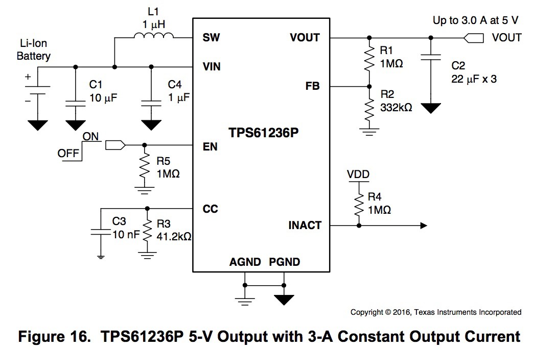
This is the schematic for a typical 5V/3A application as shown in the data sheet:
![]()
But the capacitors shown in the schematic are not really the correct capacitor values needed for proper booster operation. This is what the data sheet has to say about the “effective” capacitor values:
“The TPS6123x requires at least 20-μF effective capacitance at output for stability consideration. Care must be taken when evaluating a capacitor’s derating under bias. The bias can significantly reduce the effective capacitance. Ceramic capacitors can have losses of as much as 50% of their capacitance at rated voltage. Therefore, leave margin on the voltage rating to ensure adequate effective capacitance. In this example, three 22-μF capacitors of 10-V rating are used.”
“The required minimum effective capacitance at input for the TPS6123x is 4.7-μF. Considering the capacitor’s derating under bias, a 10-μF input capacitor is recommended, and a 22-μF input capacitor should be sufficient for most applications. There is no limitation to use larger capacitors. It is recommended to put the input capacitor close to the VIN and PGND pins of the IC. If, for any reason, the input capacitor cannot be placed close to the IC, putting a small ceramic capacitor of 1-μF or 0.1-μF close to the IC's VIN pin and ground pin is recommended.”
So why are my capacitors so big? I’m using a 47µF//1µF at the input and (3or4)x47µF//1µf at the output. Mostly it’s because I have a given inventory of capacitors and I don’t want to pay exorbitant prices for a few more. So I have to compensate for that.
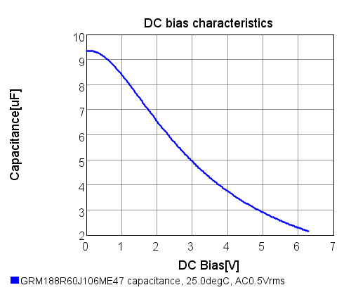
The data sheet recommends a specific capacitor C1 for the booster input: a Murata 10 μF 6.3 V, 0603, X5R ceramic (GRM188R60J106ME84). If you spend the time to locate the data sheet and look at the bias voltage variation you’ll eventually find this plot.
![]()
Note that the capacitance is about 3.5µF with a DC voltage of 4.2V. It appears that TI is cutting it a bit close here. Maybe they are hoping that C4 can make up the difference, but C4 is only 0.3µF at 4.2V, so the grand total is about 3.8µF at the input. So much for a minimum requirement of 4.7µF.
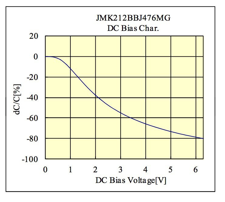
I rooted around Digikey to find out what the voltage variation for my choice of input capacitors might be. I’m using a 47µF (6.3V, X5R, 0805) in parallel with a 1µF (16V, X7R, 0805). The typical bias voltage variation for the 47µF X5R is shown in this graph.
![]()
The capacitance falls off by 75% with 5V across it!!! But even so, the effective capacitance is still around 12µF. The 1µF doesn’t add much to this, but is there to improve ESR at high frequencies. It appears that my design meets the minimum effective capacitance requirement even after factoring in the 20% initial tolerance and temperature effects.
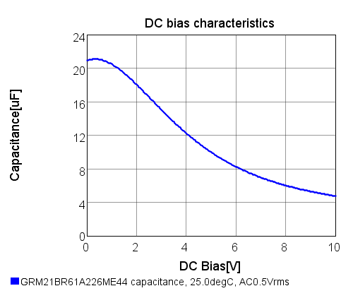
OK. Let’s take a look at the output caps. TI is using 3x22uF (10V, X5R, 0805). Here’s the voltage bias curve of their suggested cap.
![]()
At 5V, the capacitance drops from 22µF to around 10µF — a fall of more than 50%. Three of them in parallel yields 30µF, which is well above the minimum effective capacitance requirement of 20µF.
My effective output capacitance with 3x47µF (6.3V, X5R, 0805 -- same as the input cap) is about 36µF, so it is similar to what TI is using, and has room for tolerance and temperature variation. In addition, you must think about the derating the capacitor voltage rating at high temperatures. Since I don't expect to exceed 85°C I think that I can get away with using 6.3V rated capacitors at the booster output. If the board had to operate above 85°C then a 10V rated cap must be used, along with an X7R temperature rating (-55°C - 125°C).
QED.
-
The Hat Version is Working
07/22/2017 at 19:34 • 0 commentsThe Hat PCB is functioning as designed. Here's a photo of it attached to my Raspberry Pi 2 B.
![]()
I ran two discharge tests on this UPS version. The first was with the red Efest 700mAh battery: it lasted 1 hour 15 minutes. The UPS lasted 1 hour 51 minutes using the black KeepPower 800mAh battery. The load for both tests was an idling Raspberry Pi 2B.
The SOT23-5 battery charger gets quite hot when charging the battery with full current, but it doesn't appear to cause any problems since the charger has a thermal limit.
At this point I'm pretty much done with this project. I will let PaulV perform the 2-3A torture testing.
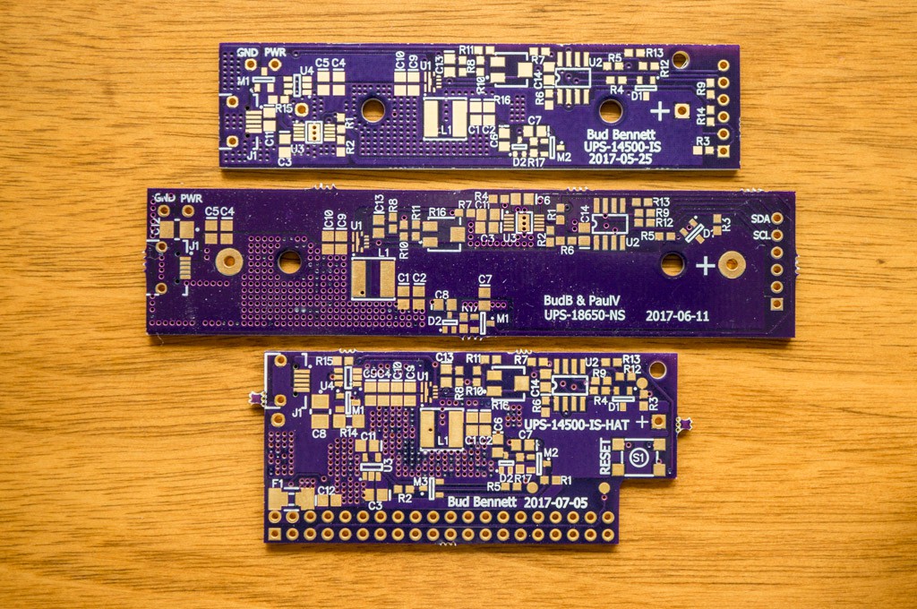
Here's a photo showing all three PCBs for comparison purposes.
![]()
-
Going forward with the Hat version
07/08/2017 at 18:46 • 0 commentsNew Information:
I'm editing this log to reflect some new testing information. I received 2 purple Efest 14500 Hi-discharge batteries yesterday (2017-07-10). When I put them to the same testing as the other batteries I noticed that something was wrong -- the battery holder started melting at the minus terminal. Apparently, the crimped connection at that terminal had become higher resistance and causing a lot of heat to build up at that junction. After I replaced the cheap Chinese battery holder with a similar cheap Chinese battery holder I repeated the testing on all of the batteries. The new results are contained in this log. I must note that the MPD battery holders are probably the ones to get -- the contacts are a single piece of flat metal that insert directly into the PCB holes -- no chance for high resistance connection unless the contact tension is weak. And I'll bet that the plastic will withstand higher temperatures. You get what you pay for.
**************************
PaulV and I have hashed out an agreement on the "Hat-like" UPS. He wanted the UPS to provide at least 3A @ 5V. I did not see any reason to provide more than 2A @ 5V. He won the argument and we are proceeding with the Hat. I've updated the log that deals with the Hat, so see that log for reference.
There are a few restrictions on the battery if you are going to provide that kind of current. I performed a series of experiments to see if any of my batteries would be able to provide more than 2.5A. Here's the results:
- Experiment #1: Initial VBAT=4.0V, Final VBAT=2.75V. Battery: Efest 14500 700mAh V1 (red). Load = 2Ω (2.5A). UPS duration: 6 minutes 18 seconds. Note: My wall wart could only provide 4.75V to a 2Ω load, so I reduced the UPS target voltage to 4.67V for all subsequent testing.
- Experiment #2: Same as Experiment #1, but the battery was a Keeppower 14500 800mAh (black). Duration: 0.1 second. (I think that the battery's protection kicked in and opened the circuit.)
- Experiment #3: Same as Experiment #1, but the battery was an Effest 14500 650mAh (purple). Duration: 8 minutes 52 seconds.
- Experiment #4: Initial VBAT=4.2V, Final VBAT=2.75V. Battery red Efest 14500. Duration: 8 minutes 49 seconds.
- Experiment #5: Same as Experiment #4, but battery was purple Efest 14500. Duration: 10 minutes 46 seconds.
When the booster is providing 3A @ 5V from the battery near exhaustion (2.75V) the current drawn from the battery will probably exceed 6A. Therefore you will need to get a battery that is rated above 6A continuous discharge current ( the "purple" Efest 14500 IMR battery is rated for 6.5A continuous, and 9.75A pulsed.)
There are a couple of take-aways from this. The type of battery that you intend to use is a big factor in the UPS performance. If you need the UPS to provide high currents then it would be wise to obtain a battery that uses IMR chemistry and IS NOT PROTECTED. If your load is less than 1A @ 5V then almost any 14500 Li-Ion battery will do the job.
The higher load current forced us to employ a poly fuse with higher current/voltage ratings, and a bigger footprint. The UPS Hat version PCB has been ordered from OSH Park and should be back from fab in a couple of weeks.
-
UPS disturbance of seismometer
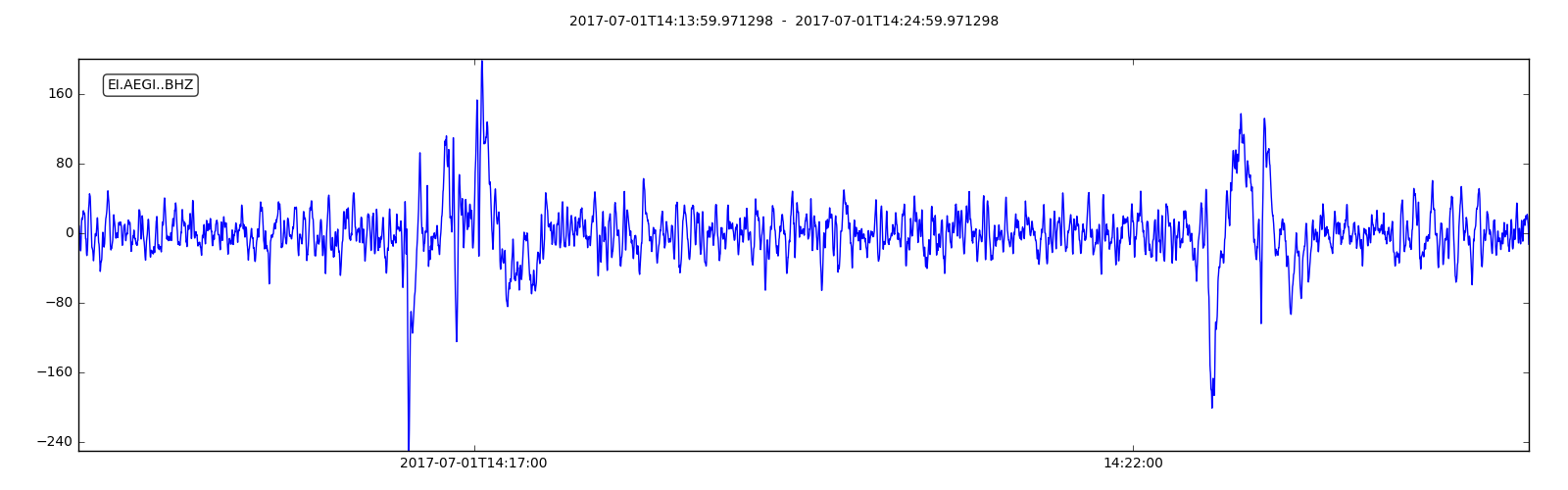
07/01/2017 at 15:12 • 0 commentsIt doesn't appear that the seismometer is disturbed by the UPS. Today I disconnected the wall wart supplying power to the seismometer, waited about 5 minutes and then reconnected it. Here's the plot from the seismometer:
![]()
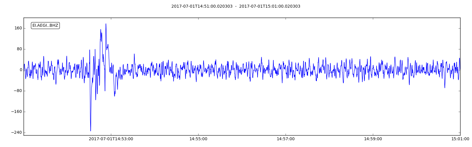
Yes...it seems like there is a problem, but apparently the problem is with me. The two major "bumps" in the data are caused by my proximity to the seismometer since I had to get down on my knees within 2 feet of the seismometer in order to unplug the wall wart. 100 counts on the seismometer ADC is equivalent to about 32 nano-meters of displacement to the concrete slab that it sits on. I repeated the experiment -- this time I only kneeled down next to the seismometer without disconnecting the wall wart. Here's what the seismometer reported:
![]()
The first trace shows very little difference (that I can determine) in the section that was running off the UPS power. I'm satisfied. Now I must wait for a power outage to see how the UPS performs for a longer period.
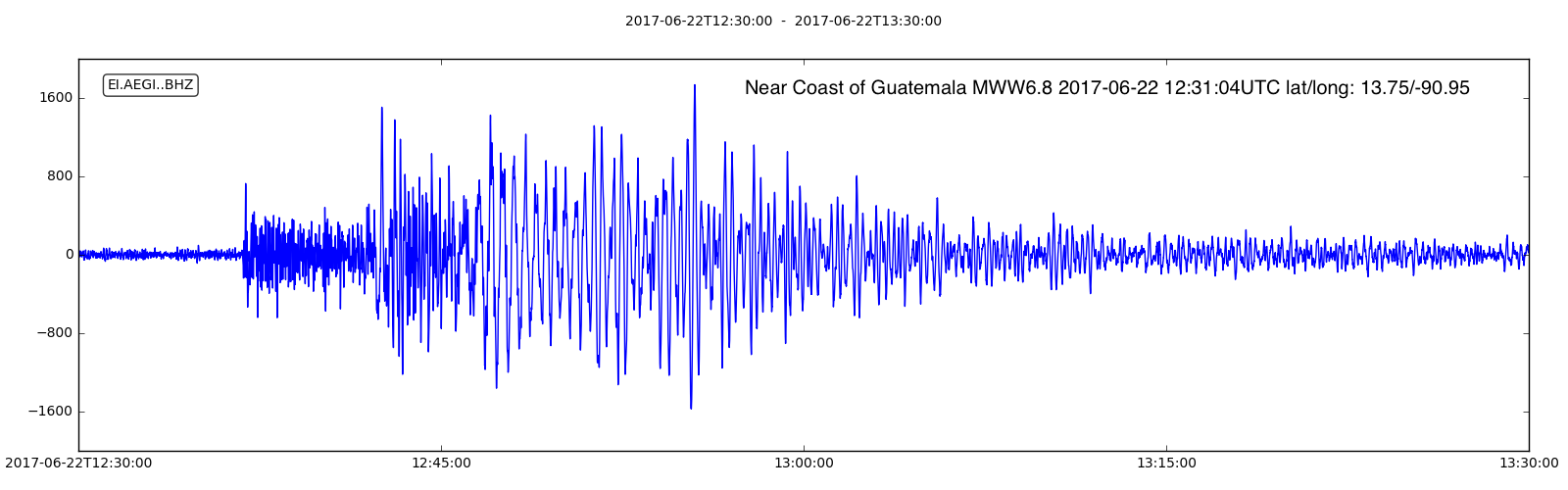
Just for grins and giggles, here's what a "real" earthquake looks like, from last week's magnitude 6.8 quake down in Guatemala:
![]()
-
UPS-18650-NS Installed on the seismometer
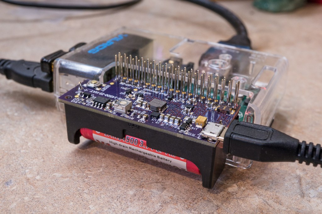
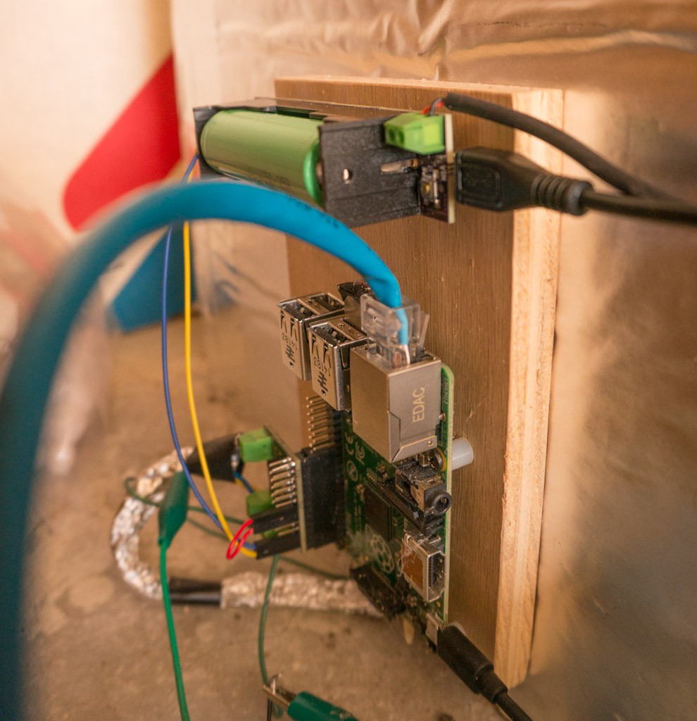
06/30/2017 at 22:52 • 0 commentsThe UPS-18650-NS is installed and working on my seismometer (I think.) The Raspberry Pi version that services the seismometer is a B+. The only way to know if it is working for sure is to disconnect power and wait 4-5 hours. Here's a photo of the installation:
![]()
I tried to get the UPS as far away from the capacitance-to-digital sensor as possible. I will have to perform a series of tests to see if the UPS needs to be shielded, but right now the seismometer appears to be working normally.
Here's the code that I'm using to monitor the UPS in the background:
#!/usr/bin/python3

'''
This program monitors the status of the UPS via the i2c interface and
manages the Raspberry Pi shutdown when the UPS signals that the battery
is exhausted. It lets the UPS determine when the battery is exhausted.
If the UPS battery voltage (VBAT) is greater than 3.2V, the status is checked
every minute. If VBAT < 3.2V then the checking interval is shortened to 1 second.
When the UPS asserts BATLOW = 1, the UPS will wait 5 seconds for the Raspberry Pi
to acknowledge by setting the SHUTDN bit. If the Pi sets SHUTDN = 1 then the UPS immediately
begins a 20 second timer to terminate the power. If the Pi has not set the SHUTDN bit
within the 5 second period then the UPS begins the 20 second timer irregardless.
So the Pi must initiate it's shutdown sequence immediately after receiving the BATLOW
signal from the UPS and sending/confirming the SHUTDN acknowledgement.
'''

from smbus import SMBus
import time, os
from datetime import datetime

ups_address = 0x36
i2c = SMBus(1)  # set interface to i2c-1
command = 0x00
VBAT = 5
bus_active = 0

def read_ups_data(address=0x36, cmd=0x00, debug=False):
    try:
        if debug: print('Sending command = {0:02x}'.format(command))
        word = i2c.read_word_data(ups_address, command)
        byte1 = 255 & word
        byte2 = word >> 8
        PWRGOOD = byte1 & 0x01
        BATLOW = (byte1 & 0x02) >> 1
        SHUTDN = (byte1 & 0x04) >> 2
        if byte2 != 0:
            VBAT = 2.048/byte2 * 255
        else:
            VBAT = 5.0
            if debug: print('ADC value error')
        bus_fail = 0
    except:
        bus_fail = 1
        VBAT = 5.0
        BATLOW = 0
        SHUTDN = 0
        PWRGOOD = 1
        if debug: print('I2C exception')

    if debug:
        print('PWRGOOD = {0}'.format(int(PWRGOOD)))
        print('BATLOW = {0}'.format(int(BATLOW)))
        print('SHUTDN = {0}'.format(int(SHUTDN)))
        print('VBAT = {0:.2f}\n'.format(VBAT))

    return PWRGOOD, BATLOW, SHUTDN, VBAT, bus_fail

time_now = datetime.now()
print("{0} Powerfail is active.".format(time_now))

while True:
    # read the UPS
    PWRGOOD, BATLOW, SHUTDN, VBAT, bus_fail = read_ups_data(ups_address, cmd=command, debug=False)

    # if the UPS has set BATLOW, then send SHUTDN command to initiate UPS shutdown
    # (but the UPS will shutdown in 5 seconds on its own...)
    if (BATLOW and not bus_fail):
        print('Sending shutdown command.')
        command = 0x04
        PWRGOOD, BATLOW, SHUTDN, VBAT, bus_fail = read_ups_data(ups_address, cmd=command, debug=False)


    # confirm that UPS received the shutdown command and then shutdown the Pi
    if (SHUTDN and command == 0x04):
        print('Shutting down now!')
        os.system("sudo shutdown -h now")
        while True:
            time.sleep(10)

    # check UPS status at 1 minute intervals until battery voltage drops below 3.2V, then
    # decrease interval to 1 second.
    if (VBAT < 3.2):
        time.sleep(1)
    else:
        time.sleep(60)
I must get around to learning about logging someday... -
UPS-18650-NS Working Prototype
06/26/2017 at 20:38 • 0 commentsThe UPS-18650-NS boards arrived from OSH Park on Saturday. By Sunday afternoon I had one of them populated and working. ( I ran out of 3.5mm terminal blocks so that will be the last board built until I get a fresh supply from China.) The polyimide stencil helped to get the solder paste aligned properly on the board, but it was a bit thick and I had to take a pin between the pads of the DFN and MSOP-10 footprints to prevent solder shorts. No shorts this time -- I'm amazed that the DFN package isn't prone to shorts given the pad spacings. If I get another stencil for these small pad footprints I will try the 3mil thickness...
Measured 30µA from the battery terminals with no voltage applied to VOUT. That's a bit higher than the 14500 design but shouldn't matter much with this larger battery. With VOUT = 5.25V, I measured 125µA into BAT, which is pretty close to what I was shooting for. I unplugged the VOUT source and trimmed the open circuit voltage at VOUT to 5.00V.
Next, I inserted a 18650 battery into the battery holder -- it seemed a bit loose so I had to bend the spring clips out a bit. When I plugged the wall wart into the microUSB jack and the plugged the wall wart into the wall socket the battery began to charge. So far so good.
At this point I was confident that the boost converter was working properly so I connected the UPS to my Raspberry Pi 2B and waited until that battery was fully charged to 4V. Then unplugged the wall wart and timed the UPS until it gave up when the battery voltage dropped below 3.0V -- 4 hours 1 minute.
I then disconnected the RPi, recharged the battery back to 4.0V, and attached a 2.5Ω load. This time the UPS lasted 36 minutes 5 seconds, from 4.0V to 3.0V. The output voltage dropped a bit, from 4.96V @ VBAT=4V to 4.94V @ VBAT=3V, but still very good line/load regulation. At the end of the test both the board and the battery were not very hot to the touch -- I estimate less than 15°C rise in temperature, which is fantastic. I measured the approximate time to recharge the battery from about 3.2V back to 4.0V -- about 5 hours, which is consistent with the 0.5A charge current and a 2500mAh Li-Ion battery.
I don't expect to perform much additional testing. The design is very similar to the 14500 design, but with a larger battery. So this prototype will be installed into to my seismometer system in the near future. I need to clean up and finish the powerfail code before that happens.
-
The 14500 "Hat-like" Concept
06/13/2017 at 18:05 • 0 commentsOK, I'll admit it right up front...I stole the idea to hang the battery upside-down off of the Raspberry Pi header from Patrick Van Oosterwijck's LiFePo4wered/Pi+ project on Hackaday. Everything else is an extension of this ongoing project.
PaulV and I have been going back and forth about this Hat concept for quite a while. I'm not really enthusiastic because some of my headless Pi systems have very sensitive electronics hanging off the header, and so placing a 1MHz multi-Ampere switching regulator nearby is not high on my list. It would be OK if the system was not required to keep operating normally (like my heating system), but my seismometer must keep going as if nothing happened, so I'll be using the 18650 UPS for the seismometer and placing it reasonably far away from the sensing electronics and most probably shielding the UPS as well.
It is called "Hat-like" because there is no EEPROM on board to make it a true "Hat".
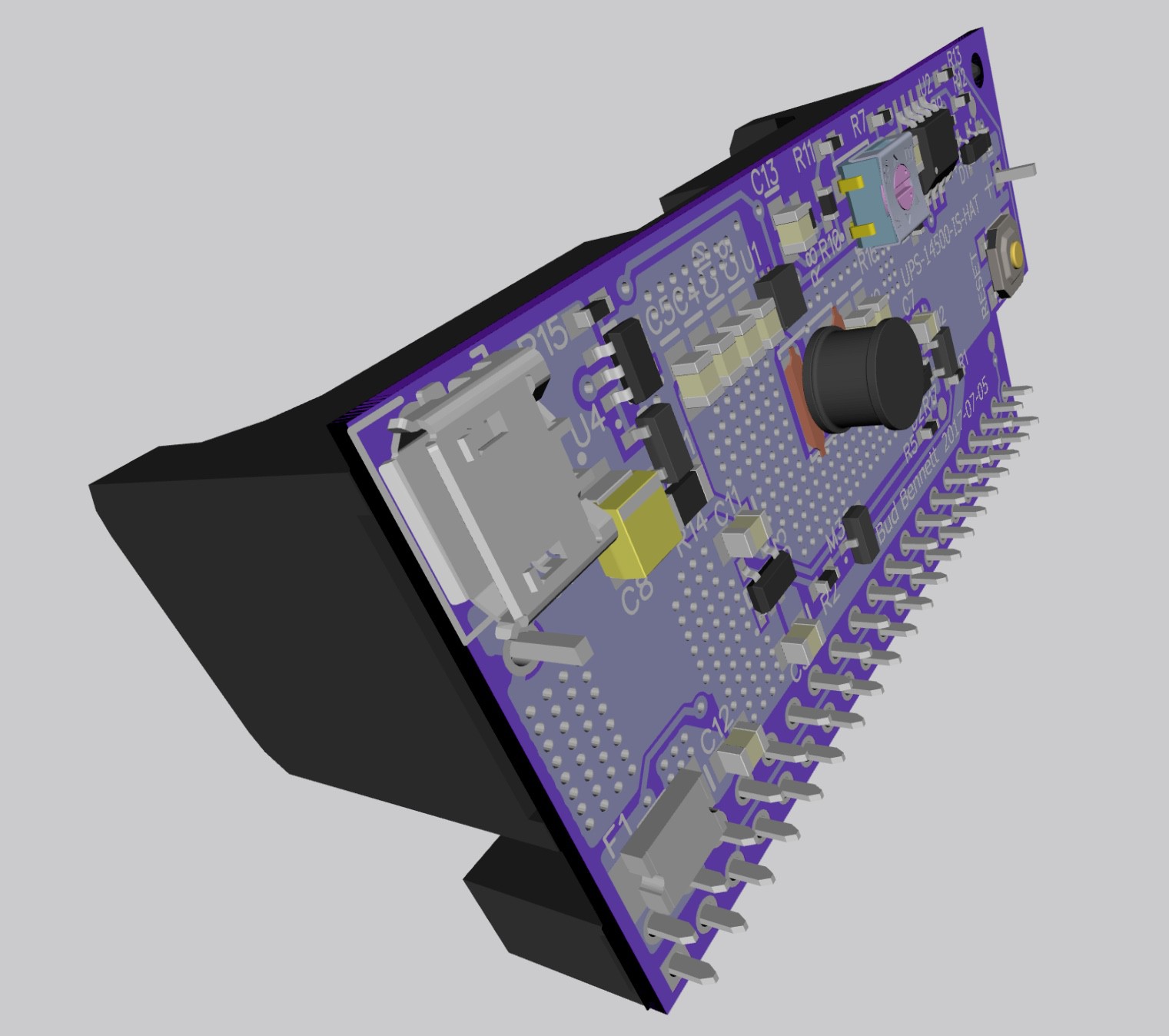
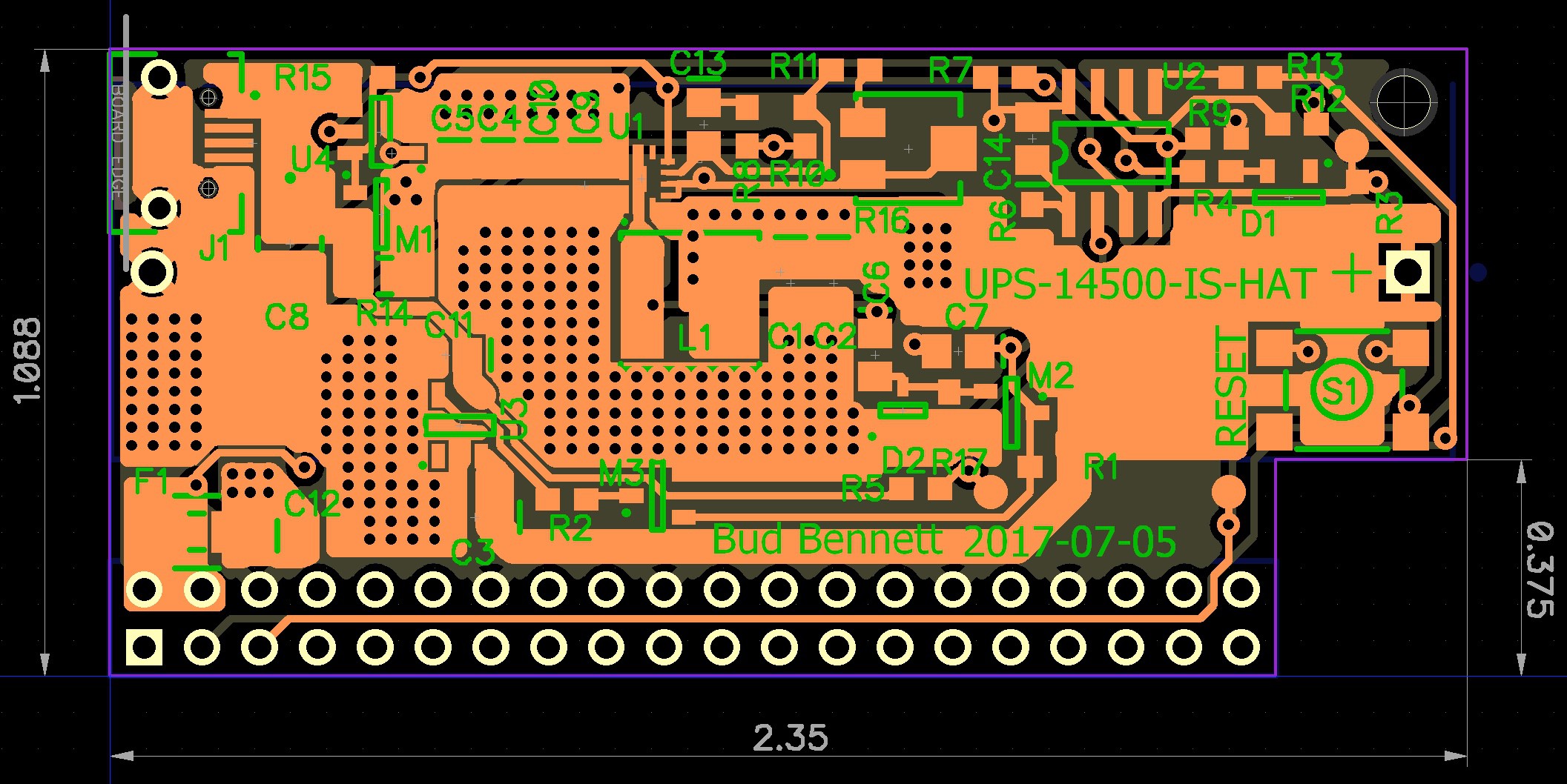
The physical nature of this UPS is its most important feature so I will start out with the 3D view.
![]()
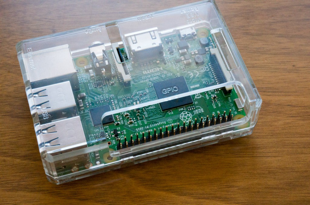
The header jack and battery holder are the only items placed on the bottom of the board. It is designed to work with the type of case shown below. It probably won't fit the Official Raspberry Pi case because there is a maximum distance of 4.5mm from the header to the battery holder, which is not enough clearance for the larger case style. I want to keep that spacing short to avoid putting too much stress on the header which will be the only thing supporting the UPS. Of course it would also work without a case, if the Pi was mounted to a surface with stand-offs.
![]()
The layout view should be considered next. Most of circuitry was directly ported from the UPS-14500-IS design. There are a few important considerations:
- The microUSB jack should probably be located to the left of the board so that the power cable doesn't interfere with the other ports of the Raspberry Pi.
- The push button reset switch had to be move to the top-side of the board for easy access.
- Because there are only two components on the bottom side of the board the goal was to make it no larger than required to support those components. As a result this PCB is a bit shorter, but wider, than the other 14500 UPS version. I believe that it is as small as possible.
- The two holes used for mounting the board through the battery holder are not required, and therefore deleted to make room for better bus width or component location.
- There is a cutout on the lower right to allow use with the planned case types.
There were some tradeoffs that had to be made. Note the VIN trace that cuts diagonally from the upper left corner of the board. It must cross the top side GND plane, which had to be compensated with lots of via hole to the bottom side GND plane.
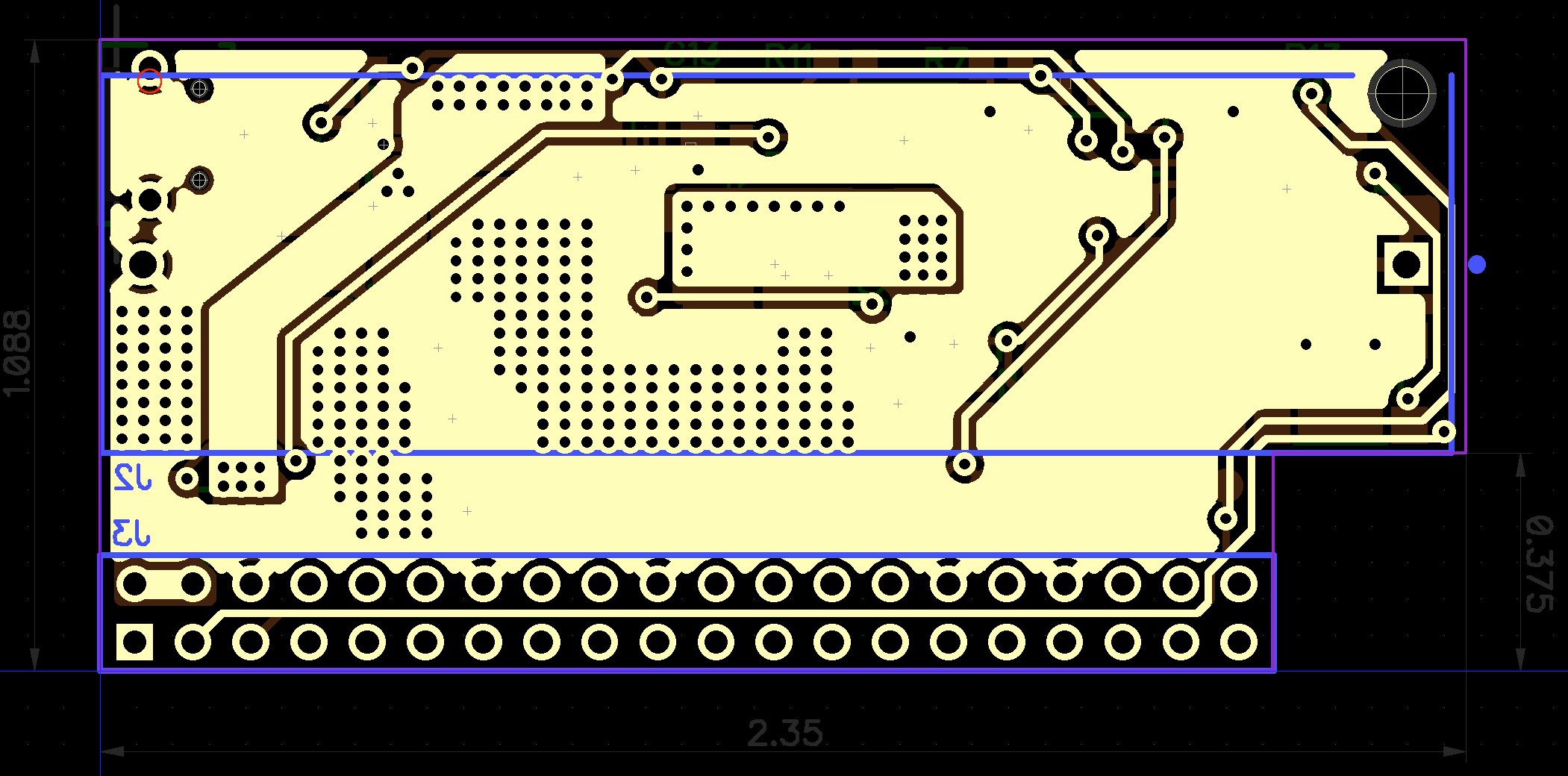
![]()
The bottom side also has a wide trace cutting across the board to connect VOUT to the header +5V pins. This time the top side GND plane was used to jumper over that trace to keep the GND resistance low. The trace widths are probably much larger than needed, but it generally pays dividends to be conservative in that area. There aren't any critical components on the right quarter of the board so the GND plane in that area is almost a don't care. Note that the PCB could be smaller along the top edge, but that battery holder locator hole at the top right needs to be surrounded by the board.
![]()
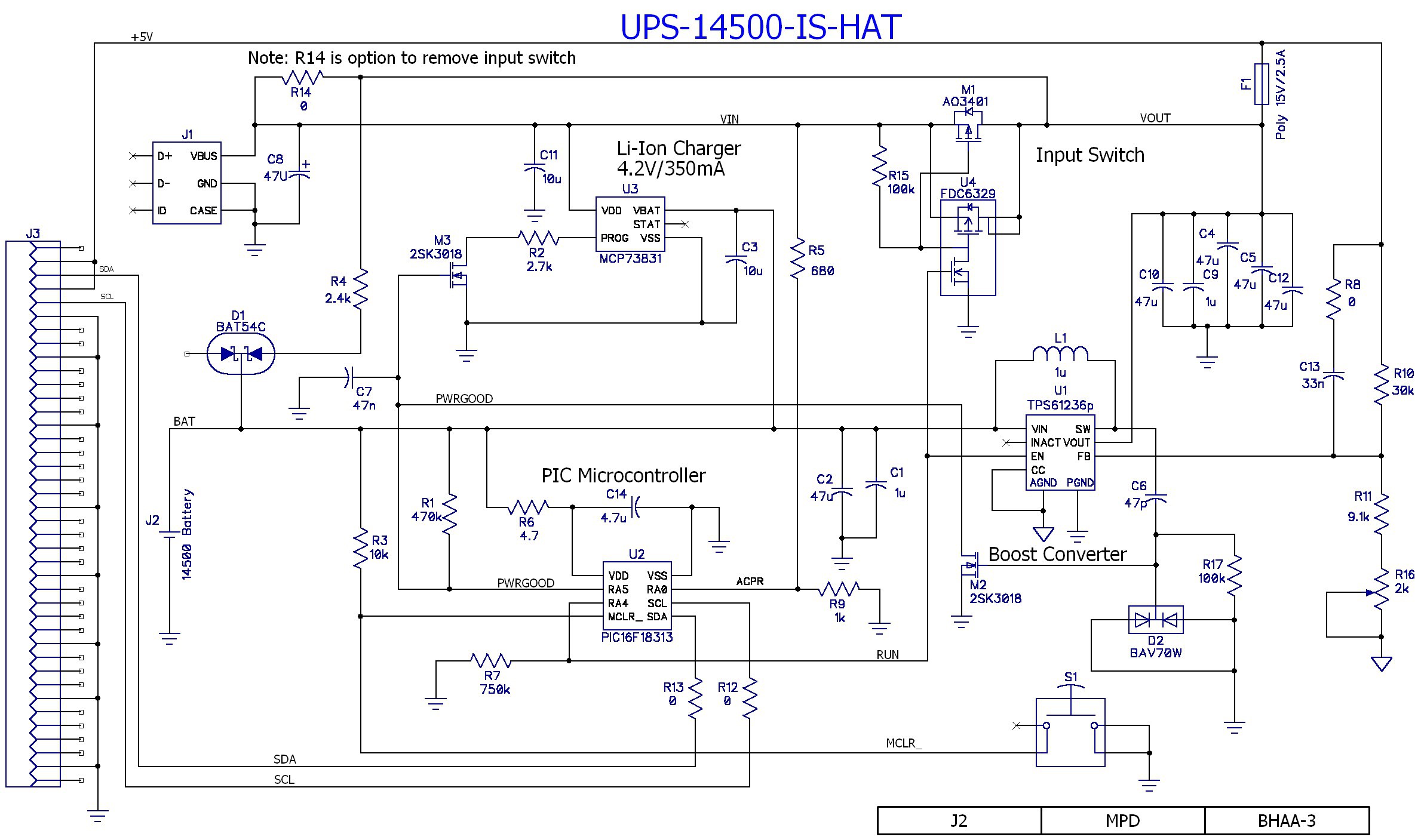
Schematic Changes:
- The LTC4064 is gone. In its place is the MCP73831/2. This new charger part doesn't have a safety timer, and charges the battery to a 4.2 termination voltage, but it is one heck of a lot simpler to handle. One of it's package options is a SOT23-5 for about $0.60 each from Digikey.
- The MCP73831 doesn't have a dedicated shutdown input, so another 2SK3018 NCH FET was added to open the programming resistor and set the charging current to zero, effectively implementing a charger shutdown.
- Since the battery charger is no longer providing an AC present indicator signal the PIC will need to be reconfigured to do it instead. R5 and R9 divide the VIN voltage down to and acceptable range for the PIC. (The PIC has a comparator block that could be used for this function, but it is probably overkill and higher current draw, so it will be plan B. Plan A is to just use the Schmidt Trigger or TTL inputs of the PIC.)
- R14 is a 1206 jumper resistor (zero Ω) that can be used to disable or remove the input switch. After getting nearly 1.5hrs of operation on a lightly loaded Raspberry Pi, it seems like an appropriate option to implement.
- The layout can accommodate either a 6V/2A 1206 poly fuse or a 15V/2.5A 1812 poly fuse because the power would be applied via the RPi header instead of the microUSB input.
- There was room on the layout to add C8 across the microUSB input. And C3 was added as a precaution to increase the stability of the battery charger when in constant voltage mode.
Here's the latest schematic that matches the layout above:
![]()
-
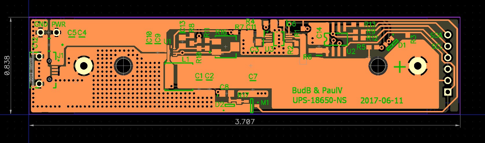
UPS-18650-NS Boards
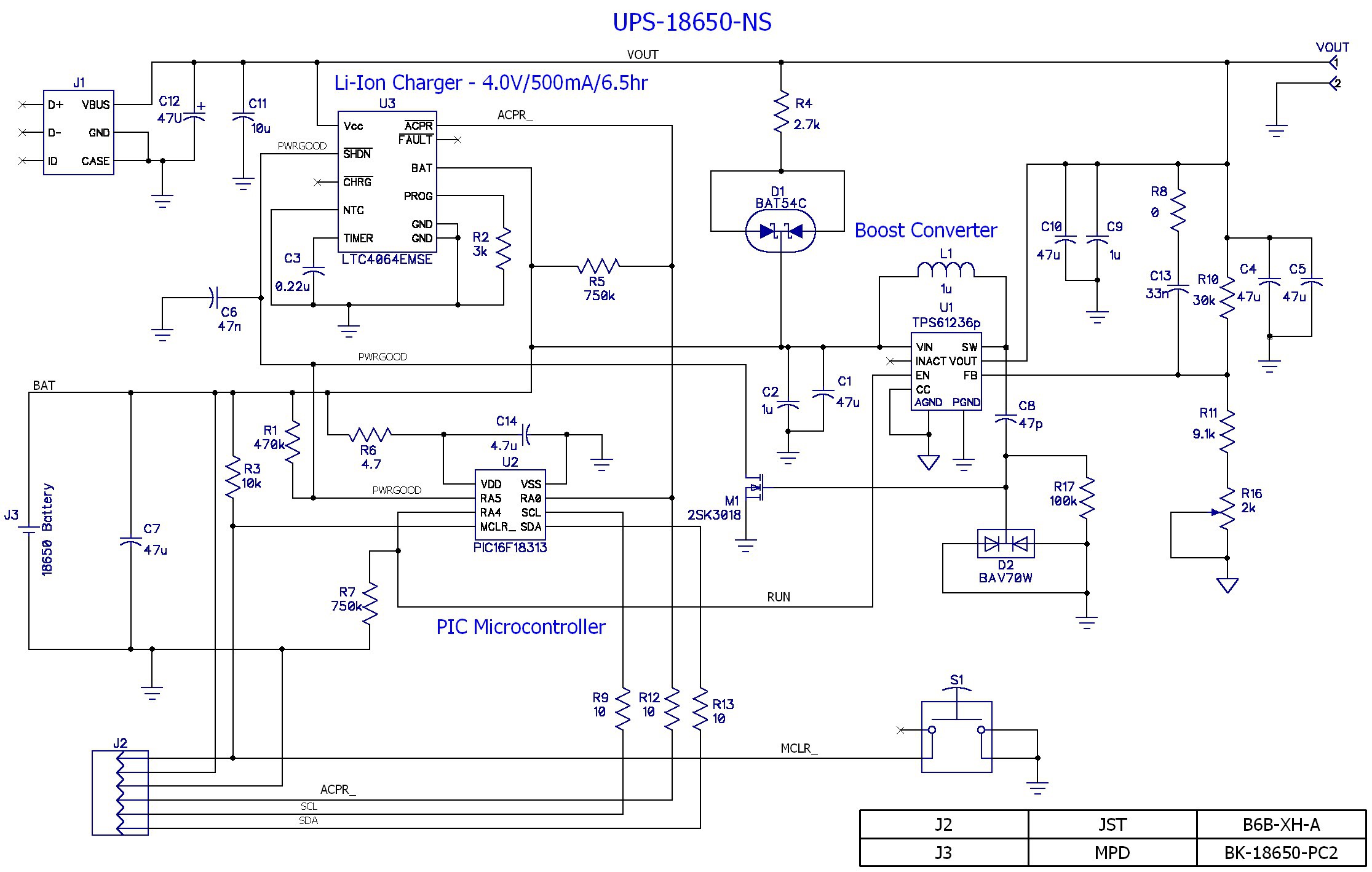
06/11/2017 at 20:11 • 0 commentsNow that the 14500 version is working, I updated the 18650 design with the necessary changes and ordered boards from OSH Park. I named this version UPS-18650-NS for consistency with 14500 naming -- the NS stands for "No Switch". The schematic is only slightly different than the UPS-14500-IS: deleted the input switch, changed the charger to 500mA/6.5 hours. There are a couple more capacitors at the microUSB input and the booster input, but they may not be populated. C12, the tantalum capacitor at the microUSB jack, is there to prevent large transient voltages when a wall wart is hot plugged into the UPS (I never intend to do that.)
![]()
The layout has gobs of empty space filled with metal buses. And the ground plane on the back side is more extensive. The metal helps to carry the heat away and keep the temperatures lower. The wide buses also keep power losses to a minimum. I'm really happy with this one.
![]()
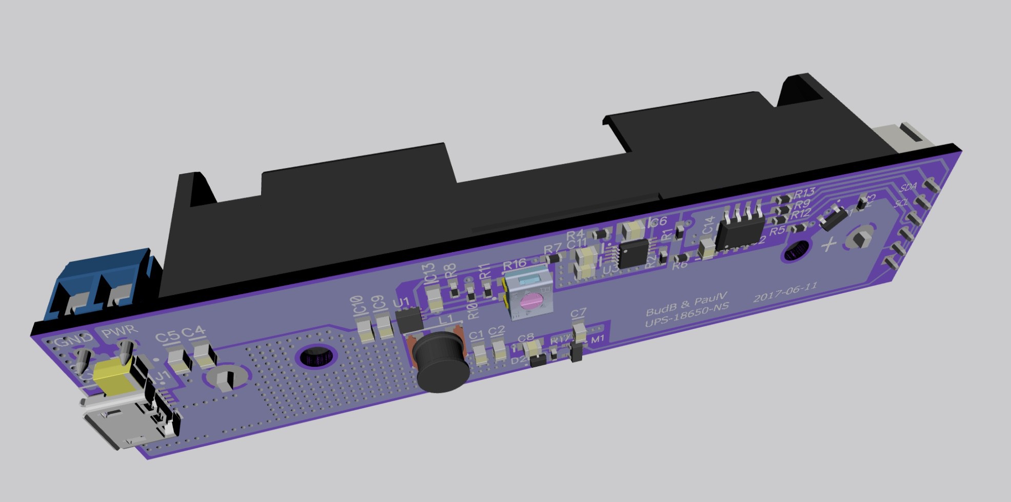
And the obligatory 3D view:
![]()
I also ordered a solder paste stencil from OSH Stencils. This time the stencil is 5mil polyimide, instead of 4 mil steel, and I shrank the stencil openings on the MSOP-10 pads. Hopefully, it will prevent the solder shorts that have been a plague on that part.
Single-cell Li-Ion Powered UPS for Raspberry Pi
A simple yet complete UPS solution for most Raspberry Pi embedded applications, using a single-cell Li-Ion Battery.