Stephen Harrison
-
Video: Reagent Tracker In Use
06/13/2017 at 20:19 • 0 commentsYesterday the second version (V1.1) PCBs arrived so I was able to [almost] fully assemble a proper reagent tracker.
I made a couple of user interaction tweaks to improve feedback to the user though the LED as a result, but here's a video of the tracker in use.
When the bottle is placed on the tracker it flashes the LED and plays the wake tune.
When the bottle is identified it flashes briefly to let the user know it is measuring the weight (it's a little slow to let the scale settle and get a reliable weight).
Once the bottle is weighted the LED lights solid until the bottle is removed, a reliable zero weight is obtained and the measurement published to the internet.
This tracker is made from FormLabs clear resin and coated with clear epoxy (and was that messy!)
-
Tracking Reagents and Getting Notifications
06/12/2017 at 02:24 • 0 commentsThis is the last piece of the puzzle to get our Reagent Tracker to a useful position.
I've used Tinamous.com as the IoT backend for this project for a few reasons, but mainly (as you can probably guess from my profile name) because I'm the founder of the site!
You can easily create your own Tinamous.com account (yes, it's free) and then invite other members of your organization to join it (for example purchasing).
For my own use case (tracking the Form 1+ resin usage in my local hacker space) Tinamous has all the functionality I need, however for a wider audience a dedicated application with predictive analytics, reports and less generic fields would be more useful.
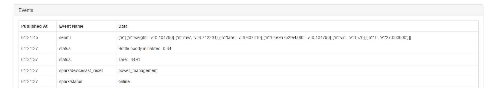
Tinamous integrates easily with the Particle Cloud via a Particle Bot, Tinamous connects to the API stream and processes the messages received in real-time. Messages published from the Photon with a "status" key will appear on the status timeline and those published with "senml" are taken as measurements. We publish the measured bottle weight as a field measurement where the field name is the NFC tag Id so it will be unique, although initially a little unfriendly!
![]()
Add Particle Bot:
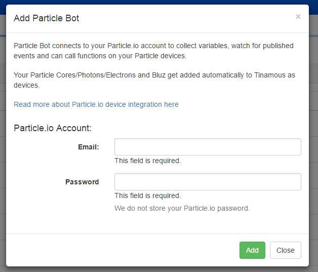
To get started we need to add a Particle Bot to our Tinamous account, this is as easy as selecting the Add -> Add ParticleBot option from the Bots page and following the instructions:
![]()
Once connected the Particle Bot will import your Particle Photons, Electrons etc. into your Tinamous account. If you already have a Particle Bot up and running then adding a new Reagent Tracker Photon will cause it to be automatically added to your Tinamous account.
Reagent Tracker Setup:
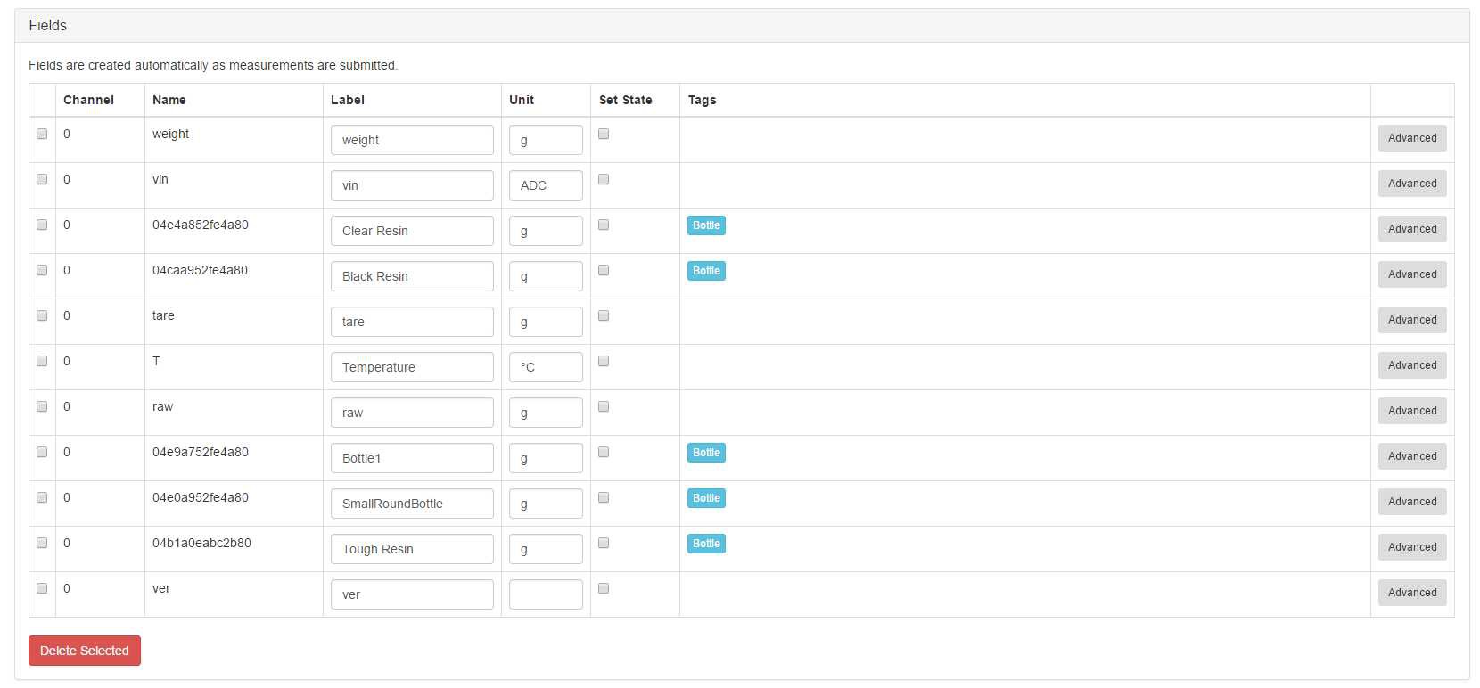
We don't need to set-up the fields within Tinamous, once the bottle tag is seen and published, Tinamous automatically adds it as a field to the device and tracks the values, however to receive notifications and make tracking a little more human friendly there are a few steps we need to take.
I changed the tags for the reagent tracker devices to a single "ReagentTracker" tag, this allows us to automatically include additional trackers into the notification group or dashboard charts.
![]()
I also changed the measurement fields that represent bottles (the field name is our tag id) to be tagged "Bottle", again this allows us to create a notification that will automatically include new bottles and help charting.
I've changed the labels to be more appropriate to the bottle (some of these are just test tags so aren't actually reagent bottles).
![]()
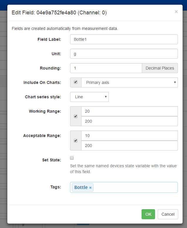
Tinamous allows us to assign working and acceptable ranges for each field, when a measurement is received that is out of one of these ranges we can trigger a notification, so for our bottles we can set-up the ranges to be the appropriate weights for empty resin bottles.
For example, below I've set up "Bottle1" to have a working range of 20-200g and an acceptable range of 10-200g. We don't really care about the upper range, but the lower range allows us to trigger notifications when it's time to order new reagent.
![]()
Notification Setup:
The following screen shots walk us through the notification set-up.
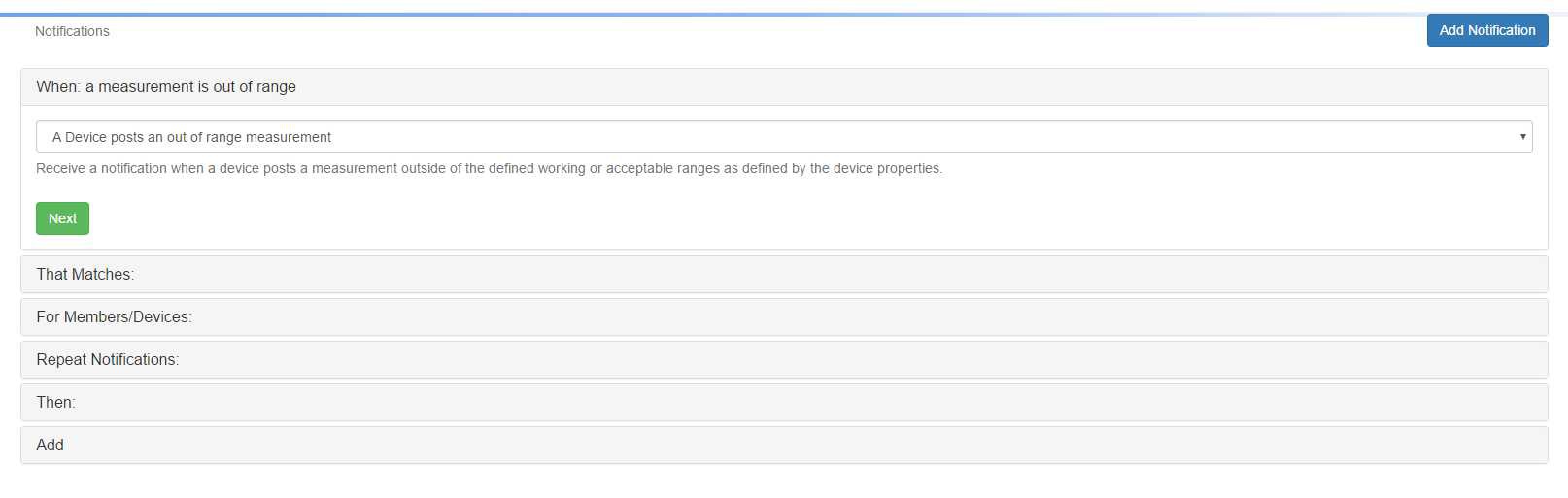
From the Notifications page, click Add Notification:
Select the "A Device posts an out of range measurement" notification type, this is triggered by the working and acceptable ranges we set-up earlier. Each bottle can have it's own unique range based on the type of bottle (glass, plastic, small, large etc.), so we are not constrained to a specific value.
![]()
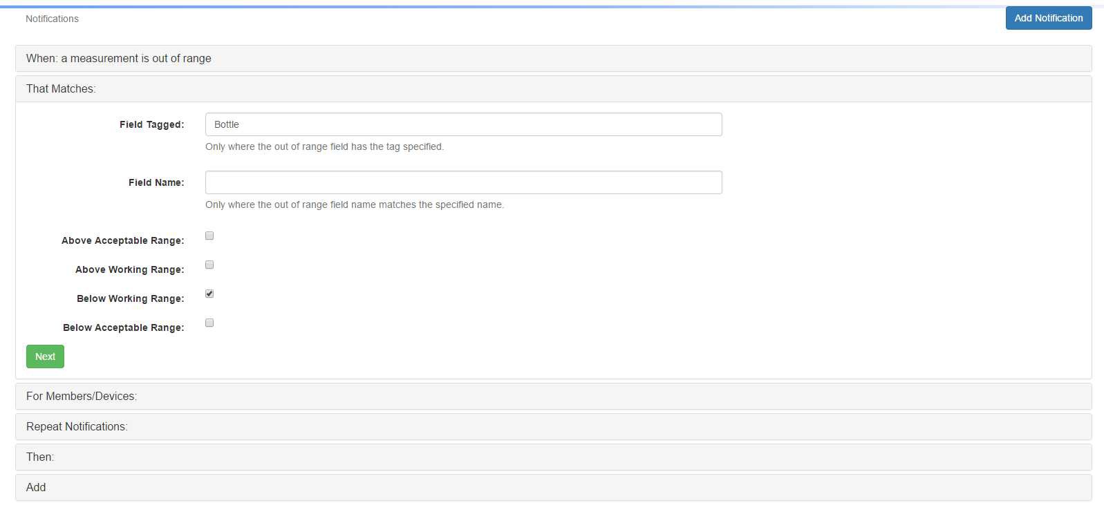
We are really only interested in the fields that represent a bottle, whilst we could also put ranges on for temperature, humidity, etc. for reagent storage, this notification needs to be triggered only for bottles. Previously we tagged our Bottle identity fields with "Bottle" so we want the notification only to trigger by fields tagged "Bottle" and we are only interested in "Below Working Range" notifications (i.e. in our Bottle1 example when the bottle weight drops below 20g).
![]()
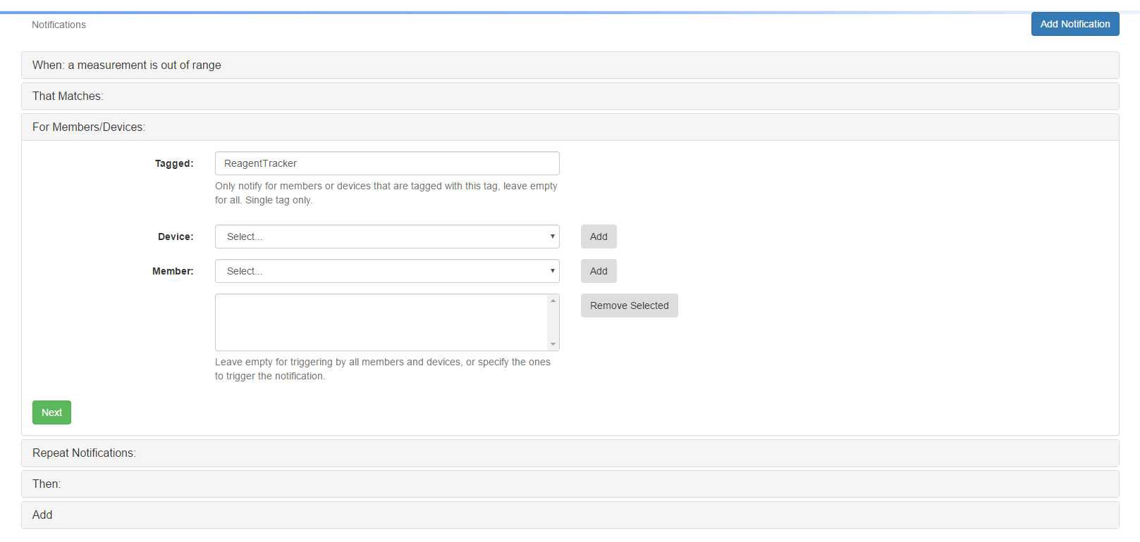
We also want to limit this to our Reagent Tracker devices, whilst it may be unlikely to have other fields tagged "Bottle" this allows us to prevent possibly confusing notifications from other sources so we filter based on the device tag of "ReagentTracker". By using the tag rather than specifying devices this will allow new trackers to be added without needing to change notifications.
![]()
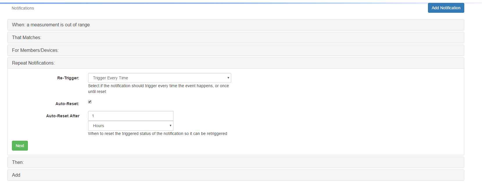
Tinamous allows you to define how the notification gets re-triggered, if were were tracking temperature it might publish a lot of measurements that were below the working range, this would result in lots of notifications, so we can add some filtering. However in this case we want a notification every time to ensure we don't accidentally miss one or forget.
![]()
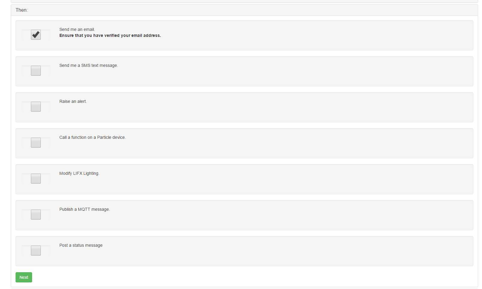
Next we get to select how we are notified. I've selected to receive an email, other forms of notification can be used as desired.
![]()
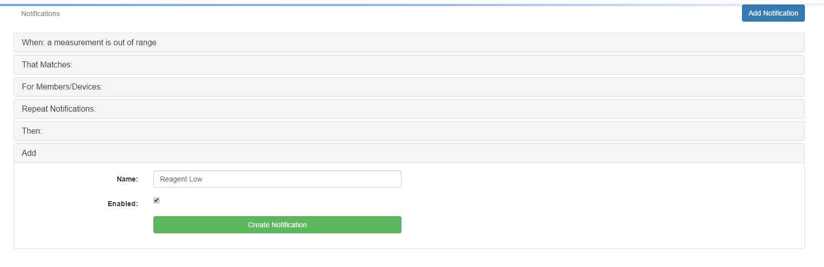
The final step is to give the notification a sensible name and create it.
![]()
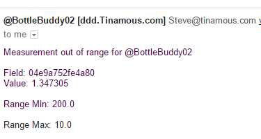
Next time the bottle is placed on the scale and is under weight an email will be sent to myself.
![]()
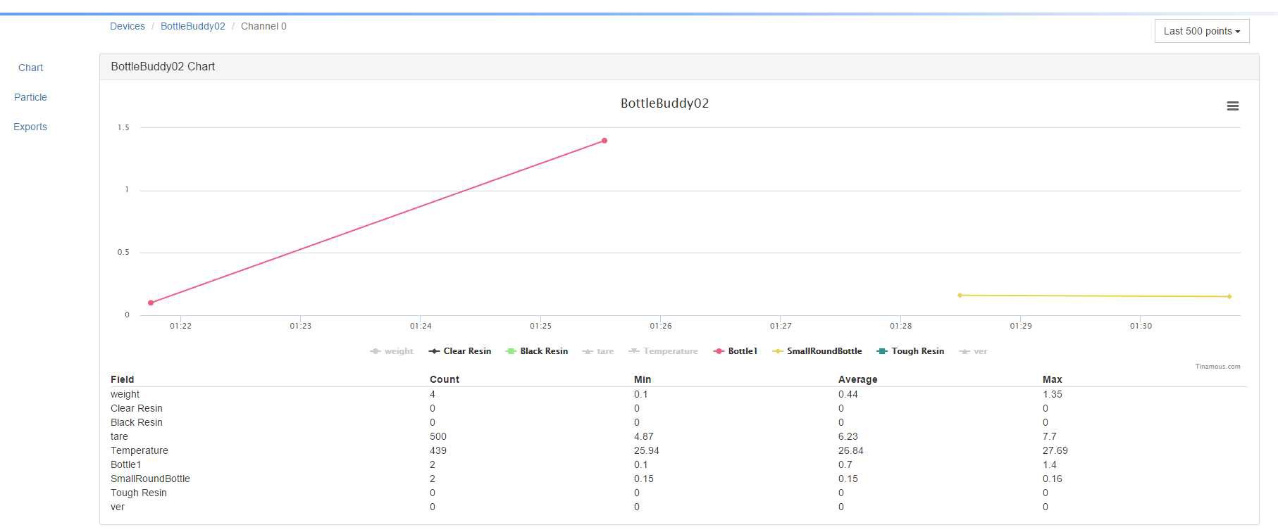
Monitoring Reagents:
In addition to notifications I can also navigate to the device page and view the chart of all the bottles that are used on that device.
![]()
-
NFC Tags
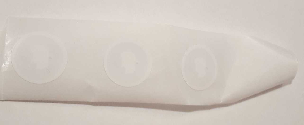
06/11/2017 at 23:57 • 0 commentsI figured the NFC tags were worth a quick mention, the ones I've used so far have been NTAG2 format round stickers I got from eBay. These cost about £5 for 10 so not free but not overly expensive either. Given these are intended to go on a bottle of resin that costs over £100 and would last for 6-12 months it's not a great overhead.
Below are the tags I got from eBay (sorry about the contrast, they are white on a white strip):
![]()
One possible use case of the Reagent Tracker is for refilling of reagent bottles. In a larger lab set-up it is common for solvents and common chemicals to be purchased in bulk and split down to more manageable sized bottles (e.g. a 20L container purchased and split into 500ml bottles as and when needed), or for somebody to make up a bulk lot of reagent (e.g. pH buffer). In this case the NFC tag stays with the bottle but the bottle may end up getting cleaned and re-used.
During my experimentation with the scale I ended up using my tea mug as a test bottle and hence it got NFC taged. I was surprised to find the tag still attached after forgetfully putting it into the disk washer. The coating was removed but the tag stayed with the mug and still worked, even after a second run through the disk washer!
![]()
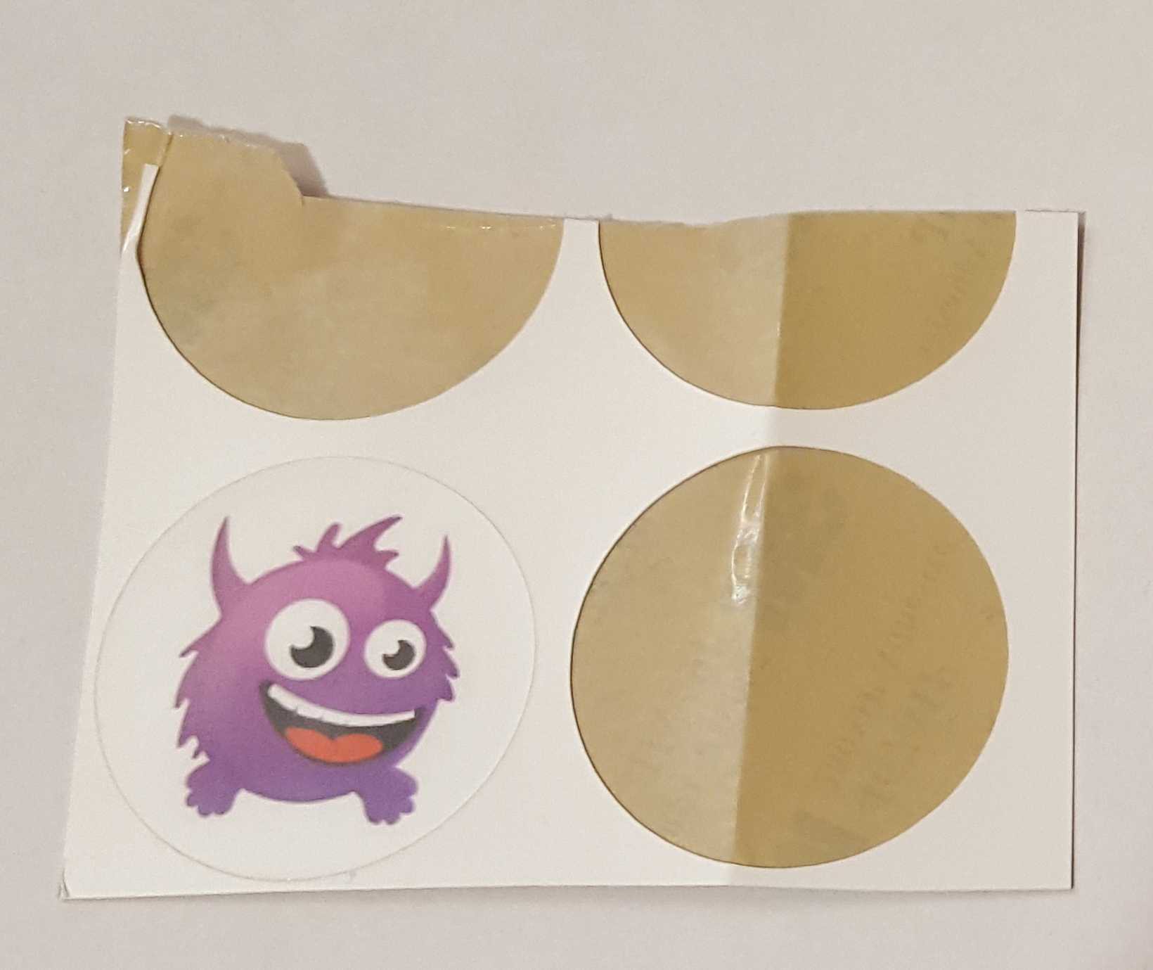
It is also possible to get custom tags, below is an example of one I've previously had made for Tinamous:
![]()
Sadly the company that made these are no longer going, however I'm sure there are other places that will do this. It can add an extra level of usefulness to the the tagging, or corporate branding, or an indication that the reagent has been though a certain process (goods in, QA etc.)
It is also possible to get the tags custom programmed, so if for example you regularly have pH 4, 7 and 10 buffers to track, you could have custom tags that include some kind of identifier data to indicate which buffer they were and have a custom colour coded image of 4, 7 or 10 on the sticker to ensure they went on the correct bottle so simplifying the tracking process.
-
Firmware
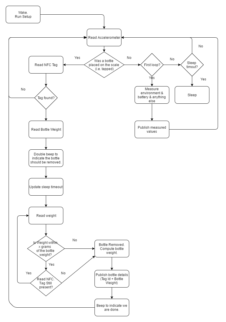
06/11/2017 at 23:12 • 0 commentsThe flow chart below describes the main functionality of the firmware.
![]()
Most of the time the Photon will be in deep sleep to save battery power, waking only because of a RTC wake or tap interrupt when a bottle is placed on the scales and occasionally due to a system event (power cycle, firmware update, user reset).
Once the Photon is woken it checks the accelerometer to determine if any taps occurred that would indicate a bottle being placed on the scale, the sensitivity of tap sensing can be adjusted if needed.
Background (no tap wake) Activity:
If no taps were observed when the Photon was woken then it is most likely due to the RTC timer timeout. Currently the Photon will take an environment measurement (temperature, empty load cell weight, etc.) and then publish this to the cloud. This may change based on use case but can be used to monitor environmental storage of the reagents should this be required.
The current version (1.0.34) uses a fairly aggressive read and publish on the RTC clock which will cause high battery drain so this needs to be optimized for the battery version, but gives a nice indication of drift of the load cell baseline.
Normal Activity:
If the Photon was woken by a tap the system then goes into measurement mode. The NFC Tag Id is read (no other information is needed from the tag), the weight of the bottle is measured and the user promoted to remove the bottle by a double beep.
With normal scales you would tare the scale first to get a good zero baseline, however because we are woken by the placement of a bottle on the scale this is not possible, so the system waits for the bottle to be removed (making an annoying beep to prompt the user in the process).
Once the bottle is removed (indicated either by a weight reduction of more than 10g, or by the absence of the NFC tag) the tare (zero) weight is measured and the overall bottle weight corrected for this. This information is then published to the back-end service.
Reading the scales requires 1-2mA, reading the NFC requires more power due to the magnetic field needed. Ideally no NFC check would be used to reduce overall power usage, however it is possible that the weight of the bottle is <10g or that the bottle was removed before the weight could be properly measured and so a 10g difference between empty and empty is not possible, hence the use of the NFC check as a backup.
Once the bottle has been removed the Photon will stay awake for 30s waiting for a possible second, third, forth bottle to be placed on the scales. This is done to try and optimized for connection time as the Photon is required to connect to WiFi and then to the Particle Cloud after a deep sleep. If many bottles are to be measured it is better to connect once and wait for the next bottle.
Power Management:
The system is mainly optimized for deep sleep current consumption, no real optimization has been done for wake power usage, for example the NFC reader could be shutdown when not being used even in measuring mode.
The Deep sleep option is used for the Photon as this gives the lowest power consumption (0.08mA cf. 1mA for normal sleep) which will extend the battery life (or at-least reduce the time between charges). With normal sleep mode the Photon can be woken by a configurable interrupt source (e.g. a change on D1, rising edge on D2 etc.), however when in deep sleep the Photon can only be woken by a rising edge on the WKP pin.
When sleeping the Photon will only go into deep sleep if certain criteria are met, the Phonon will not sleep if any of the following happen:
- A measurement is being taken or has occurred in the last 30s
- The Keep Alive pin (A2) is pulled high.
- The WKP pin is high (a tap interrupt) if this is not cleared it would result in the Photon never waking.
Internet Connectivity:
Publishing to the internet is done via the Particle Cloud functions. Particle.publish() is used to publish either a "status" message or a "senml" message, these are well known message types used at Tinamous.com and will result in the message either being shown on the status timeline or set as a measured field value.
When publishing a senml message, (in the senml json format), we set the fieldname to be the bottle NFC tag id, this allows Tinamous to track that bottle, however it will not be able to track it across two different Reagent Trackers if more than one is in use.
The Photon is set to not connect to the Internet (or WiFi) by default so some extra work is needs to be done to connect when needed, we also include a timeout for connect so in the event of a problem the battery isn't drained just trying to get a WiFi or Internet connection. If the Photon fails to connect it will emit a series of buzzes via the Piezo buzzer.
The application also exposes a few Particle.function's. These are internet callable functions that are used to configure the unit on first use. The tare function sets the zero weight of the scale into a EEPROM. This isn't a true zero as the load cell will drift but it gives a good starting point and allows us to track long term drift of the load cell. For these functions to be accessible the Photon needs to be connected to the internet, so the KeepAwake pin should be set high to run these (or the firmware altered to prevent deep sleep, or a longer timeout).
Calibration:
The calibrate function is used to calibrate the load cell. Each load cell needs to be individually calibrated to determine its response to mass. This routine is hardcoded for a weight of 666g (yes I had a 666g weight I used - actually it was a mug of tea!). It is best done with a serial connection to the Photon to get feedback and should be run a few times to get the best factor. See the HX711 driver for more information on this. See also he SparkFun HX711 Github repository
Eventually you will end up with a scaleFactor for the load cell, this should be used in the scale.set_scale() function call in setupScale(). The current value of 400.8 works well for the load cell I have but will be different for yours.
Some optimization of this still needs to be done and ideally the scale will compute it itself and store in EEPROM rather than in the code.
User Interaction:
One of the aims of the project is to keep user interaction to a minimal, hence their is no display and no buttons on the system.
- When the Photon is woken by a bottle being placed on the unit it plays a small wake tune.
- When the bottle needs to be removed the user is promoted with a double beep and a lit LED.
- A Short beep after the bottle is removed and the LED being turned off indicates the measurement has been uploaded and the next bottle can be placed on the scale.
- Additional bottles being placed on the scale do not cause the wake tune (unless the unit powered down) but will generate the double and single beeps.
Currently a reverse wake tune is played when sleeping, however this is not needed (and it's annoying) so this will be remove in future versions, but it's handy when trying to debug issues to hear that the unit is sleeping.
If the Photon is unable to connect to the internet a series of beeps are played.
The Piezo buzzer is run at max volume (50% PWM duty cycle) and about 4kHz which is around the resonant frequency for the buzzer. The PWM may be altered to play different notes to make it a little more interesting.
The user does not need to switch on, or off the system.
-
Programming The Photon
06/10/2017 at 02:33 • 0 commentsThe code is the same as Arduino code (.ino) with some enhancements for the Particle system and uses a few C++ drivers so should be fairly easy to understand for most. I've attached the fimware to the project as a zip file. This includes the source files and a prebuilt binary file that can be flashed onto a USB connected Photon with the Particle CLI. However this log is about getting the code into the Particle build environment to allow it to be modified and programmed OTA to a Photon.
If you've not worked with a Photon before check out the Particle.io getting started guide.
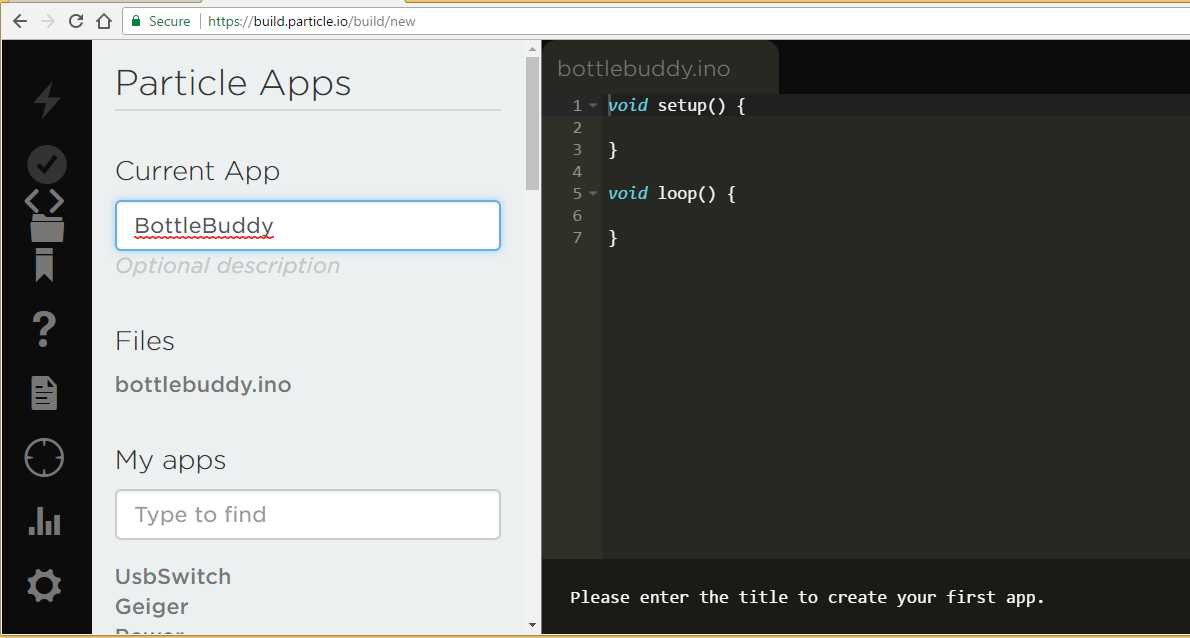
Note that the code is called "BottleBuddy", this is the project name for the hardware side of things, where Reagent Tracker is the overall project / system name.
To use the code open a new code application in the Particle Build environment (https://build.particle.io). Unfortunately at present Particle don't have a nice way to bundle applications for sharing using the build environment so this is a little messy.
Open the build environment, you will be promoted with a blank application:
Give it a name.
![]()
Paste in the bottlebuddy.ino code.
Add the following libraries using the Build library manager:
- Adafruit_PN532
- neopixel
- OneWire
Add new tabs using the (+) in the top right:
- HX711
- SparkFunMMQ8452Q
You should get a .cpp and .h tab for each of those. Paste in the appropriate files (note theirs a bit of a bug where pasting in the .cpp code will end up in the .h file as well).
The HX711 library is available through the Particle Library system as HX711ADC however I had some issues with it at the original time of writing so brought it into the project as a C++ file, also the tare function uses an incorrect type (double should be long).
The MMQ8452Q library didn't support configuration of tap interrupt events so I've modified that slightly from the original SparkFun library to support Tap Interrupts.
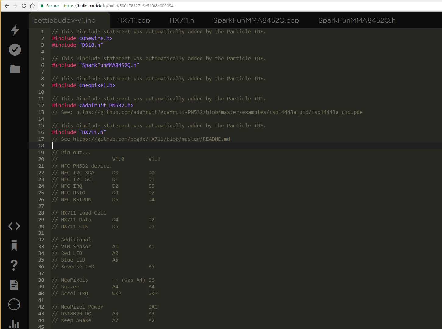
You will find the build environment has duplicated the #include statements. Remove the duplicates.
It should look something like this:
![]()
Ensure you have the correct device selected and the firmware version is set to 6.2.
Ensure that the pin definitions in the .ino file match your build, these have changed between V1.0 and V1.1 of the PCB.
Click the verify icon and the application should build.
Now click the Flash icon to program the Photon code. It may take a little time initially to get the Photon's base firmware up-to 6.2, updates after this are lightning fast.
Once the Photon has been flashed it is going to spend most of its time asleep so we won't be able to re-flash the device without doing something special. At this time the standard build environment doesn't support queued firmware updates so we can't build the code and request it to be flashed on next connect. I think the product deployment functionality on Particle is able to do this, but it's not really suitable for 1 or 2 devices and still requires you test your firmware on a device or two first.
Their are a few ways to keep the Photon connected to allow firmware updates. The KeepAwake pin (A2) is probably the most useful, particularly on a prototype board set-up, notice the white flying lead below, this connects to 3v3 to keep the application awake. V1.1 of the PCB has a (KeepAwake) test point that can be soldered too if required.
![]()
Alternatively we can place the Photon in Safe Mode, this is handy to know about not only for firmware updates but for when we mess up the firmware and are not able to get the Photon to connect.
To place the photon in Safe Mode, hold both Set-Up and Reset buttons down, release Reset and wait for the LED to flash Purple (it does this almost immediately), then release the Set-Up button. The Photon will now connect to the Particle Cloud and we can updated it, but it won't run any of our code until it is reset (manual or due to firmware update).
-
Electronics
06/08/2017 at 03:08 • 0 commentsThe electronics side of the scales is made up of the following modules:
- Micro-Controller
- RFID Reader
- Load cell and amplifier
- Accelerometer
- Environmental sensors
- User interaction (LED, Buzzer)
- Power
- NeoPixels
Also covered are:
- PCB and System Design
- Prototyping
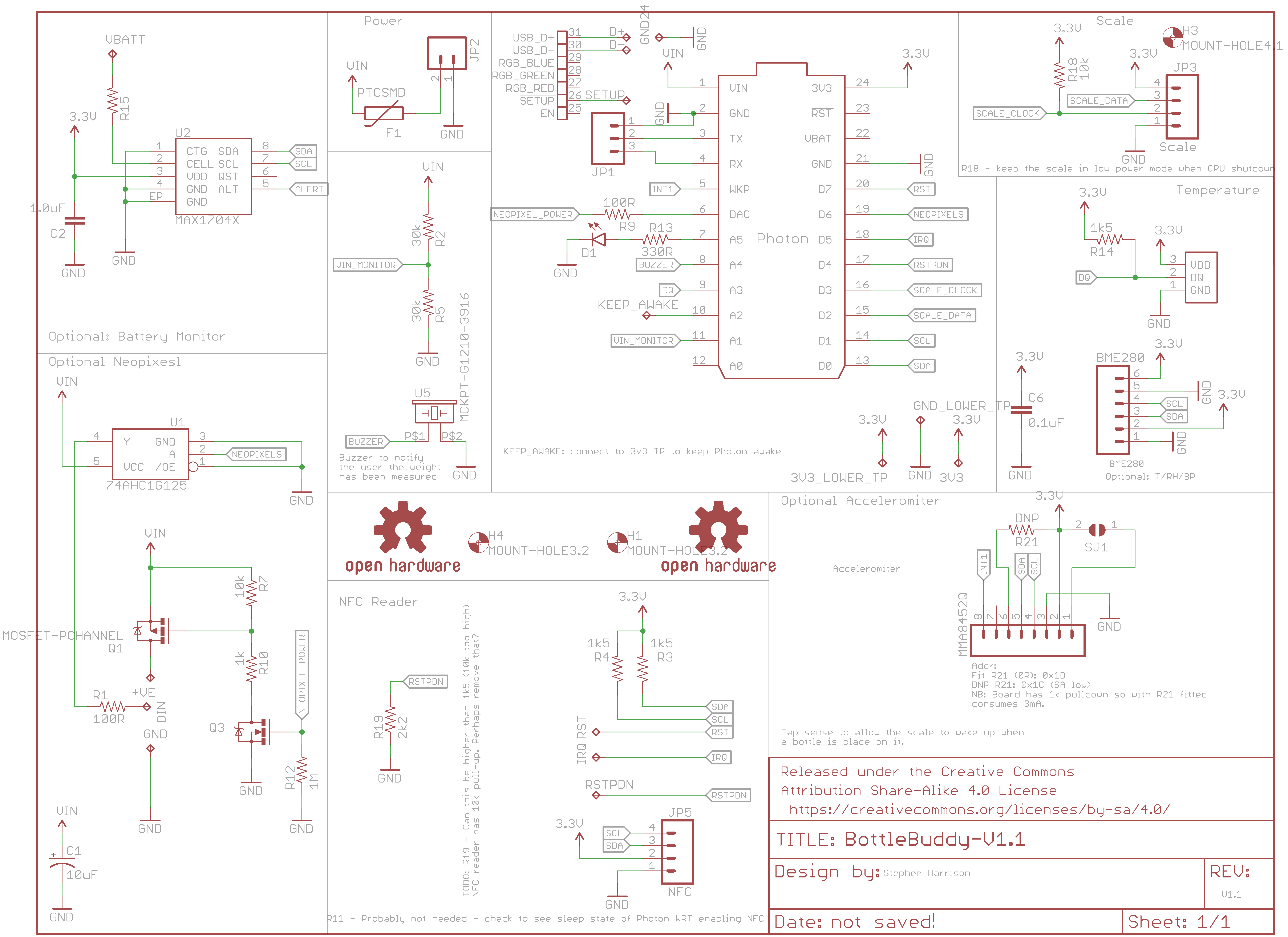
Schematic:
![]()
Micro-Controller:
A Photon from Particle.io is used in this project for the micro-controller and internet access. I've used Photons in numerous other projects and they work really well and are very easy to work with.
The core features of the Photon for this project are:
- Built-in WiFi
- Good selection of low power modes (down to 80uA in deep sleep) and wake interrupts
- Very easy to publish data to the internet (via the Particle Cloud)
- Good API at the Particle Cloud
- Good library of drivers and essentially Adruino compatible
- OTA deployment so no USB connection required
- Previous experience working with it
- Integrates easily with Tinamous.com which makes the prototype version quicker to develop
The Photon can be put into deep sleep which stops all functionality but allows it to be woken by a RTC timer (x seconds after sleeping) or a rising edge on the WKP pin. (Special care needs to be taken when using the WKP pin as the RTC also uses this, if the pin is prevented from going high it will block the RTC wake as well).
The Photon has various digital GPIO's, 7 Analog (also digital) GPIO's, two serial pins (Tx/Rx) as well as the serial port exposed over USB, possible battery back-up of SRAM variables via a dedicated VBAT input and 2k onboard "EEPROM" flash memory.
As the Photon is designed to be always powered by the VIN pin from battery or external power we don't need to supply anything to VBAT and any retained variables stored in SRAM will be kept as long as we have power. Long term variables such as load cell calibration values can be stored in the EEPROM to survive power loss.
Like most micro-controllers, when the Photon is in deep sleep mode we lose control of the GPIO and cannot guarantee the state of the pin so special attention needs to be paid to GPIO pins
The Photon is intended to be in deep sleep most of the time with only occasional waking when a reagent bottle is to be measured. It may be desirable to have the RTC wake the unit to send a signal to indicate that the unit is still functional and monitor battery charge but this will need to be balanced with battery usage as WiFi connectivity draws a lot of power.
For the first version of the PCB I used the "header" through hole version of the Photon but switched to the headerless SMD version for V1.1 as this reduced vertical height and saves trimming the legs of the Photon (they are long and protrude a long way though the PCB where space is at a premium).
RFID Reader
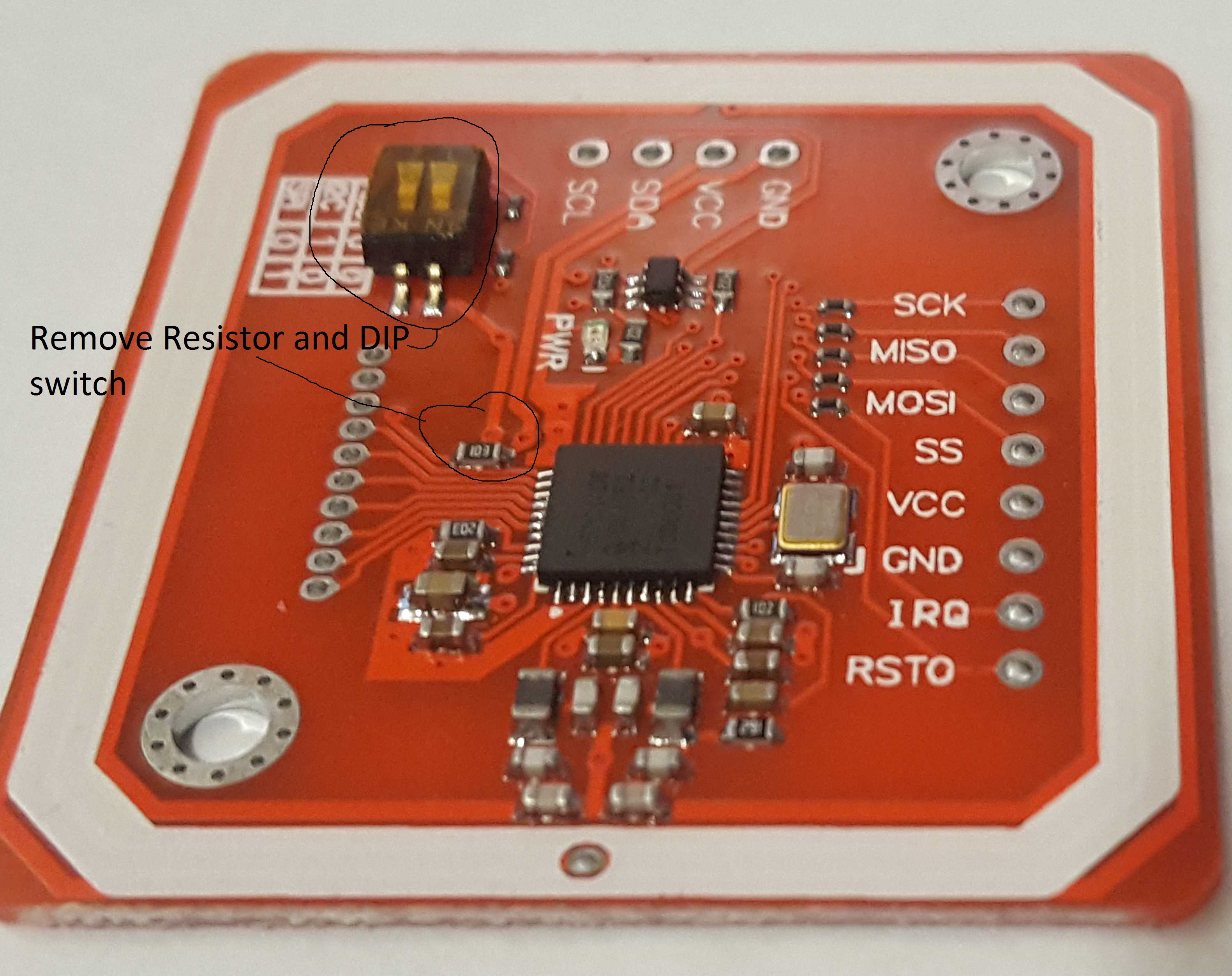
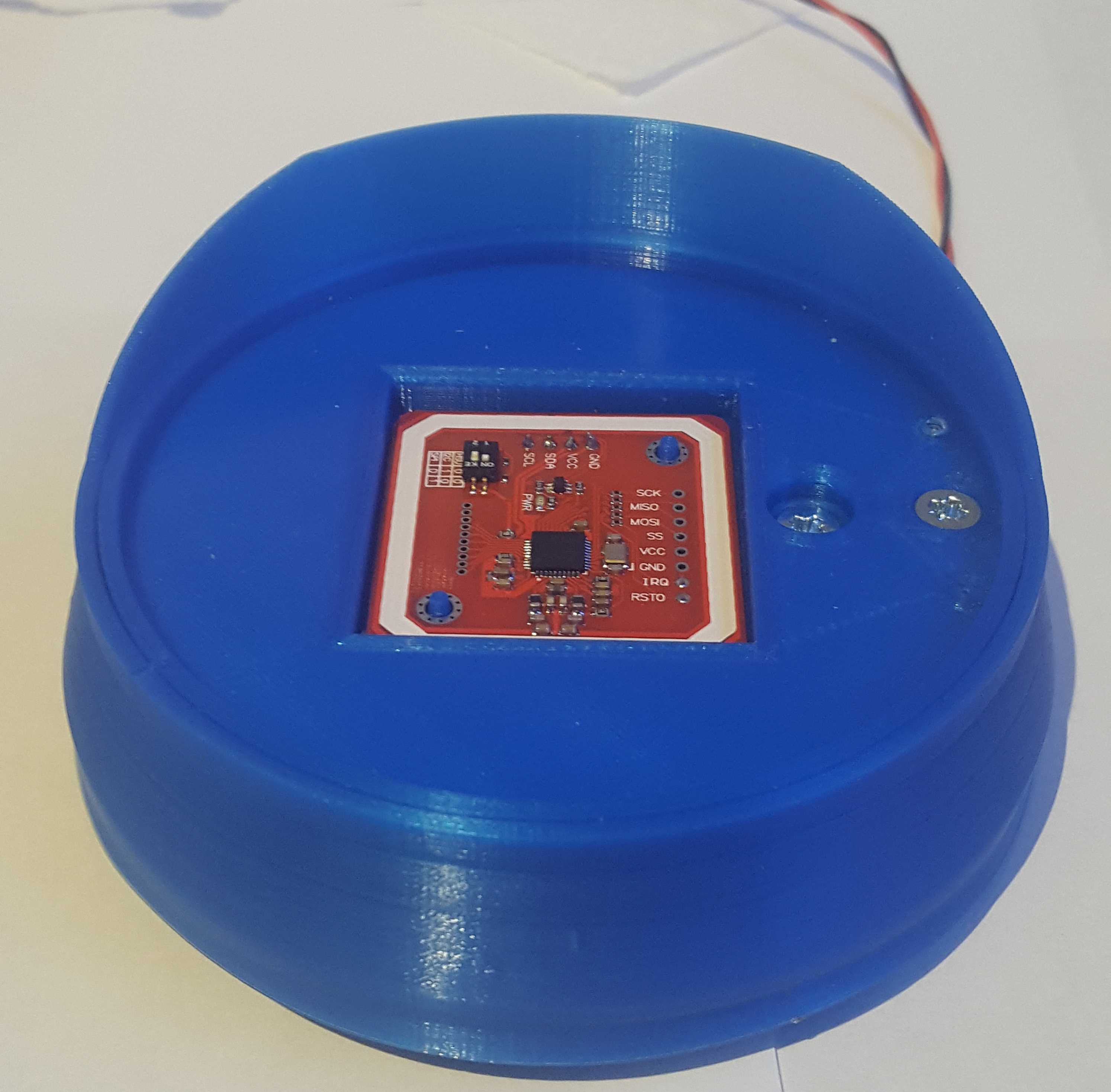
As mentioned in the 3D case design the RFID reader was one of the more troublesome selections and I finally settled on the PN532 small red board version available through eBay. This supports NTAG2 tags (these appear to be the only format ones I can get that are stick-on type suitable for the bottom of the bottle).
The PN532 supports I2C, Serial and SPI modes. We're going to use I2C as it simplifies the design needing only 2 wires for the bus and is used for other components. This means that the DIP switch seen upper left in the picture needs to be set to I2C mode (the switch on the right needs to be set towards us). However during final build this will be encapsulated in epoxy so it's going to be better to remove that switch and hard solder the connection to prevent possible vibrations changing the switch which we then can't change, or epoxy getting in and forming an insulation barrier between the switch contacts - it will also reduced the height of the unit by 1.6mm.
![]()
In addition to the I2C and power connections (top centre in the picture) we also need IRQ and RST. These are available bottom right (although this is RSTO and not RSTPDN so further investigation is needed to check which RST the driver actually needs as it is unclear).
The PN532 has RSTPDN pin which is broken out on the bottom left in this picture of the PCB which when pulled to shuts down the PN532 and RF circuits. This gives a much lower current consumption than the software shutdown option so we want to use this to save power, when the micro-controller is in shutdown we have no control of the GPIO pins and these may not be in the desired state so an external resistor (R19) is used to ensure the PN532 defaults to this state.
Unfortunately the NFC PCB has a 10k pull-up resistor on the RSTPDN line (understandable as it wouldn't work out of the box otherwise), but this means we need a smaller resistor to ensure the line is pulled low, with this resistor fitted I'm using a 2k2 resistor to pull the line low, this means we have 410uA (I = V/R -> 5v/12.2k -> 0.000409A) current consumption just from those resistors which is undesirable. Hence for final assembly R19 should be replaced with a higher value (10k+) and the NFC RSTPDN pull-up resistor removed as shown in the above picture.
According to the datasheet the PN532 will run at 2uA in a hard power down and 10uA in soft power down. However for soft power down the PCB has the LED lit which increases the power consumption, but the hard power down significantly reduces the power consumption.
I elected to have the NFC PCB component side up on the case, this allows a good fit with the print underneath to (hopefully) stop epoxy running through before curing, it also means that the LED on the PCB is visible and as this is controlled by the RSTPDN option it results in a nice feature of being able to tell if the system is powered and functioning.
![]()
When running with RF enabled the NFC PCB can consume bout 100-200mA so minimizing this time through software is obviously going to help improve battery life.
Load cell and amplifier
Their are a few options for load cells, the type typically used in bathroom scales are different from the one used in this project, they use 4 sensors to spread the load, this then requires additional wiring to get them connected. The type used in the Reagent Tracker is fairly common for kitchen scales as it has a small design and good weight range and sensitivity. Whilst the load cell should be capable of sub-gram measurements this project needs only 1-2g (and maybe less) accuracy as we are looking for a large range of difference (e.g. a full bottle may be 1kg compared to 100g for an empty bottle with and a re-order trigger at 250g, hence a few grams error isn't really going to make a difference).
A quick look at the SparkFun Force sensors category shows the various options. The load cell selected was based on lower cost, easier to connect up and mount as well as sensing range and sensitivity. A lot of force sensors merely indicate a force is applied and are unable to give any kind of accurate measurement.
The load cell and amplifier were sourced (like a lot on this project) from random sellers in China from eBay. Each load cell will have it's own characteristics as they are essentially individually drilled blocks of Aluminum with hand placed strain gauges, hence loads will place different strains on the strain gauges. I would expect the load cell used in this project to be very similar (if not identical) to the load cell available through SparkFun and they have a good guide to hooking up load cells which is well worth a read (https://learn.sparkfun.com/tutorials/load-cell-amplifier-hx711-breakout-hookup-guide).
It is possible to buy 1Kg as well as the 5Kg range load cells, however the 1Kg cell would not be enough for a full 1L bottle of resin so the 5Kg version is used which means we have a very slightly reduced sensitivity but not enough for concern for this project. If you are building your own and are interested only in light bottles you may wish to swap to a 1kG load cell.
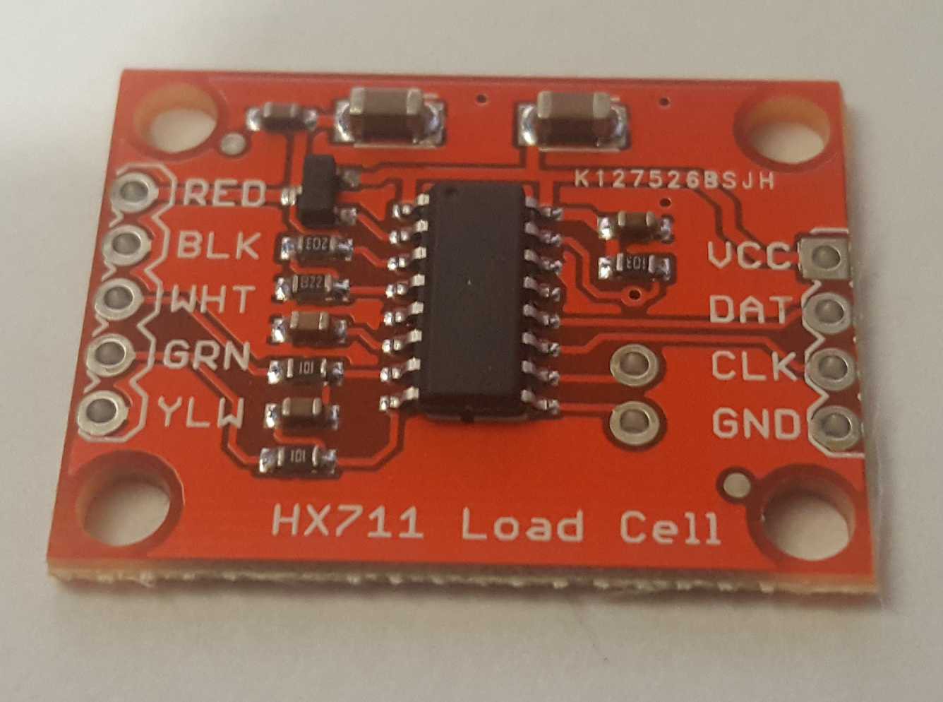
The load cell amplifier was a little problematic to source, again a few versions exist, I tried the blue PCB versions available on eBay but didn't have much luck and eventually settled on the red PCB version. This looks to be identical to this Spark Fun version, however I've not tried this. It appears all the commonly available amplifiers are based on the HX711 IC, this proved difficult to source alone so I opted to piggy back the red load cell amplifier onto the main PCB rather than try to source the amplifier, let alone develop the correct PCB layout for such a sensitive ADC.
![]()
The amplifier is used in its default state (10 samples per second), again special care has been taken for power down. The HX711 will sleep when the CLK pin is pulled high, so R18 pulls this pin high by default to allow the amplifier to sleep when the Photon is in deep sleep.
Normal operation of the HX711 uses about 1.5mA and sleep is down to 1uA so again ideally we will keep the amplifier in its sleep state.
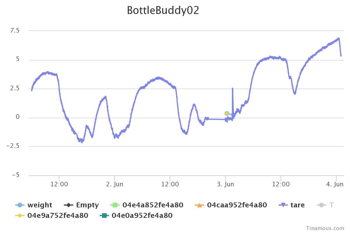
One initial intended use of the Reagent Tracker was that it would also be where the reagent was stored, e.g. with 5 Form1 resin bottles, 5 Reagent Trackers would be used to store the bottles in a nice shelf configuration, this would mean that tracking reagent usage was automatic once the bottle was returned to it's location. However initial tests showed that the load cell drifts (without load and with small temperature changes I observed about +/-10g drift) and this can be more with load applied to the strain gauge. Whilst this mode of operation is still possible by continuous measurement and checking for the bottle removal so a tare and loaded weight are measured at a similar time it does make operation more error prone).
Load Cell Drift:
![]()
Accelerometer
The use of an accelerometer wasn't part of the original (V1.0) design and was introduced when realizing that a better mode of operation was to have a single Reagent Tracker that bottles were placed on as and when used.
With typical kitchen and laboratory scales, after switching them on you tare the scales, then place the item to be weight onto them and observe the weight. However Reagent Tracker is designed to have as little user interaction as possible, we don't want to ask the user to switch on the scales and tare them, and certainly not write down the bottle weight!
This is where the accelerometer comes into it's own. A MMA8452Q is used, this has 2 programmable interrupt sources and can generate an interrupt when tapped. This is ideal for our use as putting a bottle onto the unit will generate the equivalent of a tap, this then creates a rising edge interrupt to the WKP pin of the Photon which will bring the Photon out of deep sleep.
Once the Photon is awake we can check that we have a bottle though the NFC sensor (the accelerometer is sensitive and will also be triggered from other "taps" that occur when things are put onto the bench next to it - i.e. my mug of tea!).
Using this tap to wake scheme allows us to put all the other components into a deep sleep mode and just run the accelerometer, current consumption is in the 6uA to 165uA range for the accelerometer which will help improve battery life. (With just the accelerometer running at about 100uA a 3000mAh battery would last > 3 years, however we have lots of other things going on!).
Again the accelerometer is sourced from a random seller on eBay (the blue version of the PCBs gives the correct pinout as used on the PCB). SparkFun also sell breakout boards however the pinout is not the same as the blue ones on eBay and for myself these can be difficult and expensive to try and source in the UK (for example, CoolComponents.co.uk have none in stock at present), hence the purchase from eBay rather than a SparkFun unit (Sorry SparkFun!).
Environmental sensors
As a basic start a 1-Wire DS18B20 TO-92 device is used to sense temperature. This may or may not be useful in the long run, but as the load cell drifts with temperature it was added to the design to try and keep an eye on this. The sensor was introduced for V1.1 of the PCB so it doesn't feature on the original version, it is placed next to the fixed end of the load cell, hopefully this will allow it to be in contact with the cell by careful (wonky) insertion into the PCB.
Additionally a 6 pin socket is provided for (again eBay sourced) BME280 breakout PCB. The BME280 will measure temperature, humidity and relative pressure. This part is totally optional but may allow for compensation due to environmental issues, or where reagent storage has critical environmental requirements this could be used to track storage conditions.
User interaction
User interaction with the Reagent Tracker is designed to be as minimal as possible, as described in the accelerometer section ideally the user will just drop the bottle onto the system and remove when the bottle has been identified, weighted and data successful send to the cloud.
To notify the user that the bottle can be removed a buzzer and LED combination are used. A short double beep is emitted to indicate that the bottle can be removed and a longer single beep that the tare (empty) weight has been measured and the bottle weight has been published. Problems connecting to the internet result in a series of error beeps.
No other user interaction is intended. It may be that in a Goods In style use case where the new bottle of reagent is received some other hardware may be used to print a more human readable label to stick to the bottle to indicate date of receipt, perhaps the RFID serial number and possibly even photograph the bottle (and automated identification of the reagent) as well as get information about the bottle. However for this simple version no other interaction is intended.
The buzzer is a piezo buzzer and is driven from a PWM pin on the Photon, as we are driving it at 3v3 only this will mean it's not very loud (esp. when inside the printed case), this is somewhat out of our control so a LED is also used. As the Piezo is PWM'd it allows us to change the frequency of the PWM and hence the note that the piezo will play should we wish to have a little fun with this!
The LED is a reverse mounted PCB LED and aligns with the hole through the top half of the case at the front of the unit. This hole goes both vertical and out the front at a slight angle. When covering the unit with Epoxy it will be desirably to block the hole from underneath and the front allowing the epoxy to form a light pipe (and not run into the inside!). The hole is 3.2mm allowing a standard 3mm LED to be pushed in snugly, or some kind of tape can be used.
If the case is printed larger than the default 100mm size, this hole can be moved forward and a normal 3MM LED fitted and wired back onto the PCB.
The buzzer and LED will only be used when in full operational mode so should not cause any drain on the battery in standby.
Power
This part of the system is still being worked on. It is intended that the battery would be a 3000mAh Lithium Ion battery similar to this one from SparkFun. Being flat gives it a good fit within the case and it's just about the right size to fit beside the load cell.
It is intended that this will be charged by something like the AdaFruit PowerBoost, however the boosting of the battery to power the circuit isn't needed as the Photon will happily work from the raw battery and everything else uses the 3v3 from the Photon.
It should be possible to use a wireless QI charger to power this, hence removing the need for an external connector however this isn't suitable for day to day operation due to the magnetic field and sensitive metal rod of the load cell not being a good combination). More investigation is needed for this.
The main PCB features placement for a MAX17043 (U2), however this is going to be difficult to solder so probably wont be fitted, likewise there was little room for the breakout board version of this, however it has been left on the PCB for possible future use and experimentation.
Resistors R2 and R5 form a potential divider across the battery input to the main PCB which will allow battery voltage sensing, however this comes at the cost of current consumption (60k across a 4V-ish input => 67uA), which when we are trying to run on battery for as long as possible is not ideal so these may be omitted (however the current used just for these will take about 5 years to flatten the battery so it's a small price to pay for being able to actually monitor the battery voltage).
NeoPixels
The PCB also includes a P-Channel FET to control the power to a possible NeoPixel ring and a level shifting buffer to bring the 3v3 signal from the Photon to the required level of the NeoPixels. Given the high current consumption and obscured view of these they are unlikely to be used but V1.1 of the PCB has the option for these anyway.
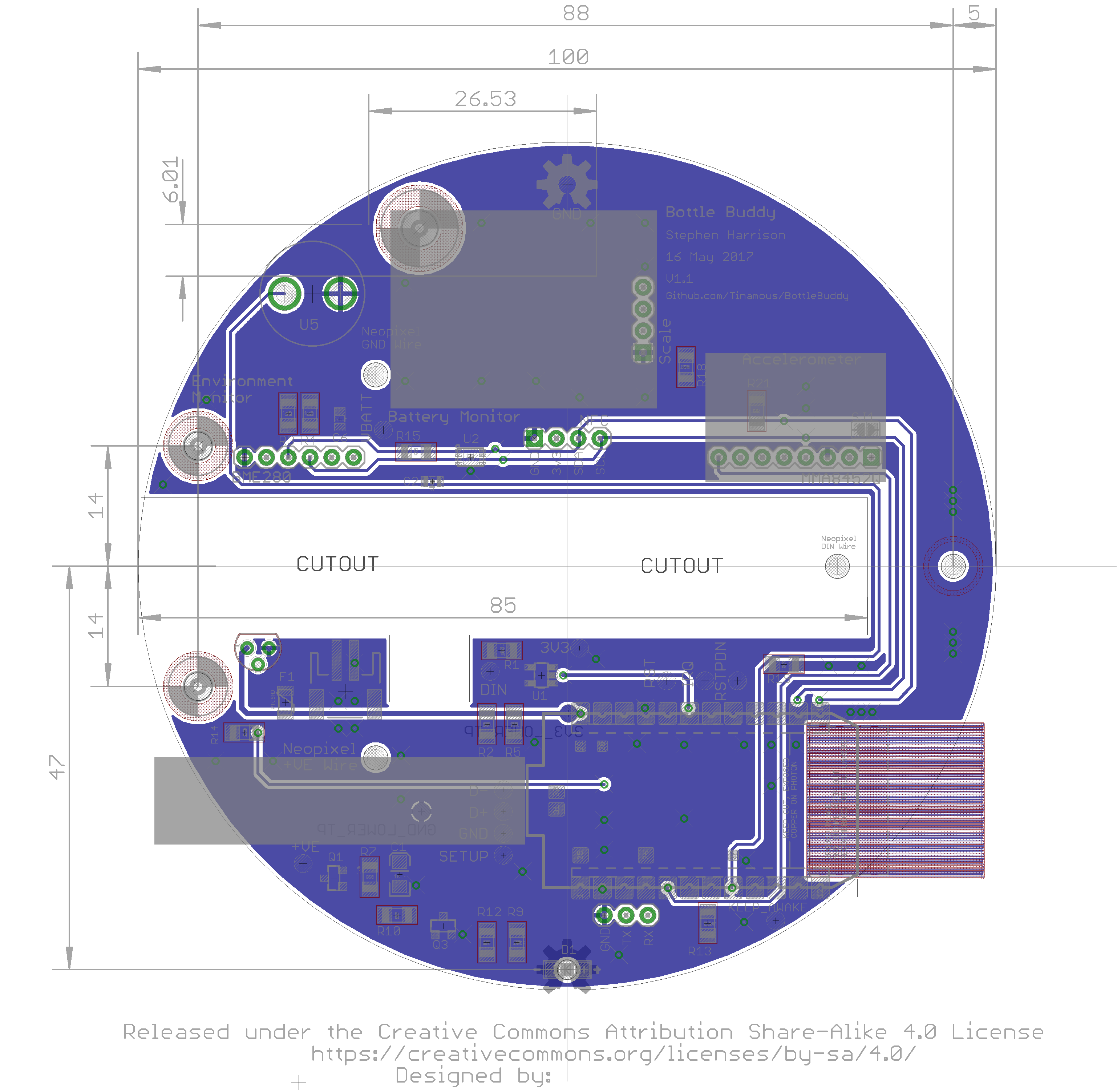
PCB and System Design
When I designed the second version of the PCB I initially went with putting the MMA8452 and BME280 onto the PCB to reduce space required inside the system as vertical height is at somewhat of a premium to allow for battery space, however to simplify PCB population I've gone with the breakout PCBs and pins to connect these to the main PCB to make assembly easier (at-least for this version). As the Photon and load cell PCB will be sitting on top of the PCB hopefully this compromise will have little effect on the internal height restrictions and a smaller battery may prove a good substitute for easier assembly.
I also elected to have a thinner than normal PCB (0.8mm cf. 1.6mm), this buys us an extra 0.8mm internally. Whilst it doesn't sound much reducing the size of each of the parts like this can add-up to a real saving in the end.
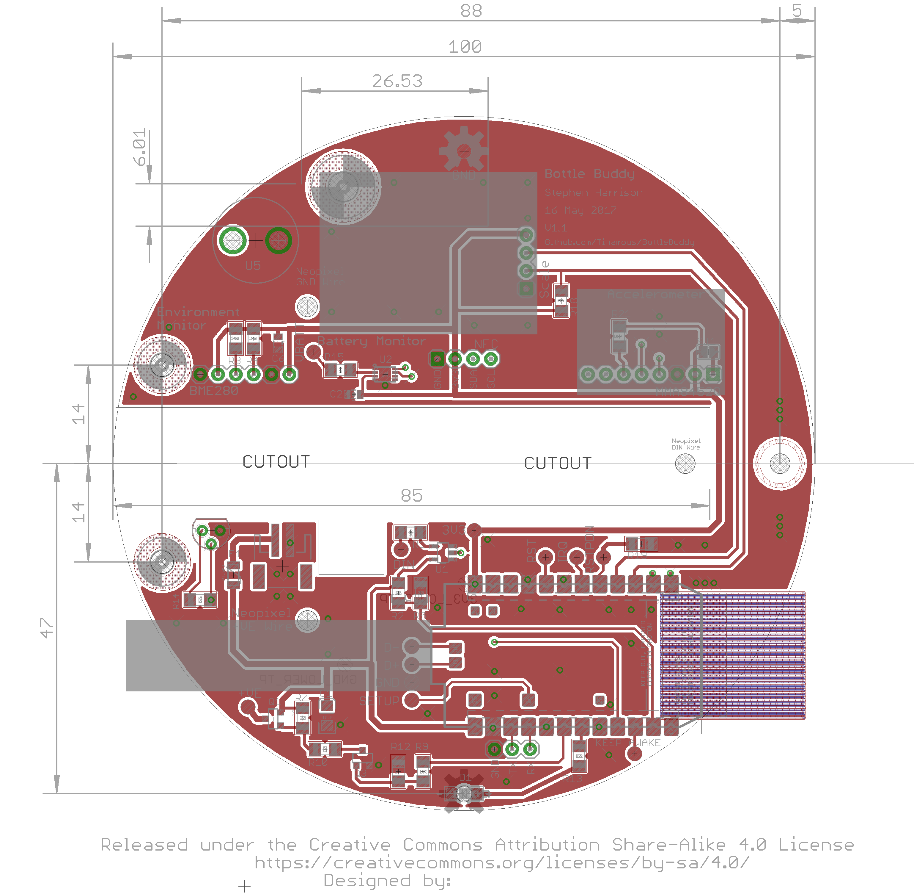
The PCB is designed in Eagle, it fits in a 10x10cm square but is a round design with a centre cutout for the load cell (Note that the load cell is slightly off centre to allow for the mounting screws to be away from the vertical RFID magnetic field). Eagle files are in the GitHub repository and on this project.
When mounted onto a PCB the headerless photon USB connector can be difficult (impossible) to connect to, the Photon exposes two pads on the underside that are brought out to test point pads on the PCB should these be needed. Likewise the Photon Setup pad is also exposed as a test point, these obviously can't be hand soldered so will require some solder paste and a trip to the reflow oven if they are required.
Pin A2 of the Photon is also connected to a test point, this is used as a "Keep Awake" indicator and when tied high (3v3) the firmware will not go into deep sleep mode, allowing for easier firmware updates or continuous operation mode and debugging.
The TX and Rx pins of the photon are broken out to JP1 (3 pin 0.1" pitch) for future expansion should so this can be connected to a 3v3 serial connector or serial display or something else.
Power is delivered to the main PCB via a 2 pin JST connector (JP2), this the same type used for the Lithium batteries so a battery can be directly connected if desired, however care needs to be taken to ensure the cable does not pull on the PCB as this will cause noisy readings and also make battery charging difficult.
The Battery and charger are expected to be fitted into the lower half of the case.
V1.1 PCB:
![]()
![]()
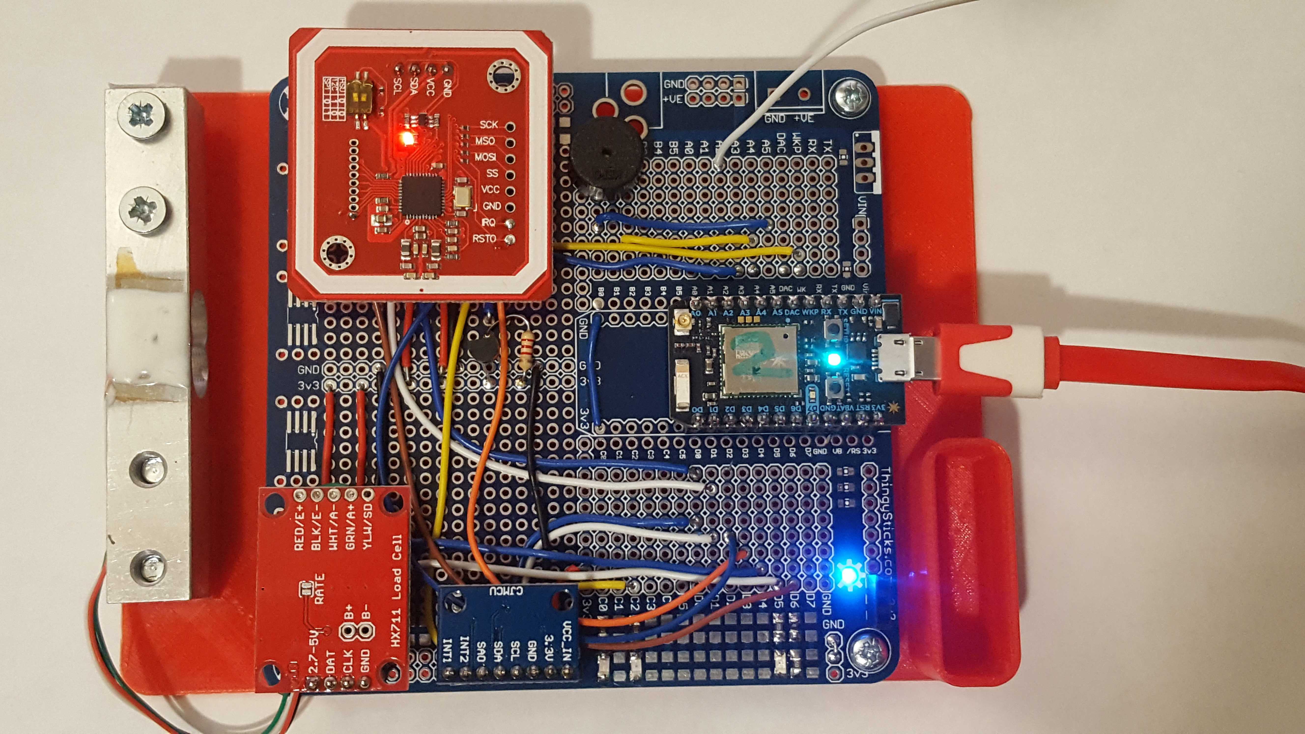
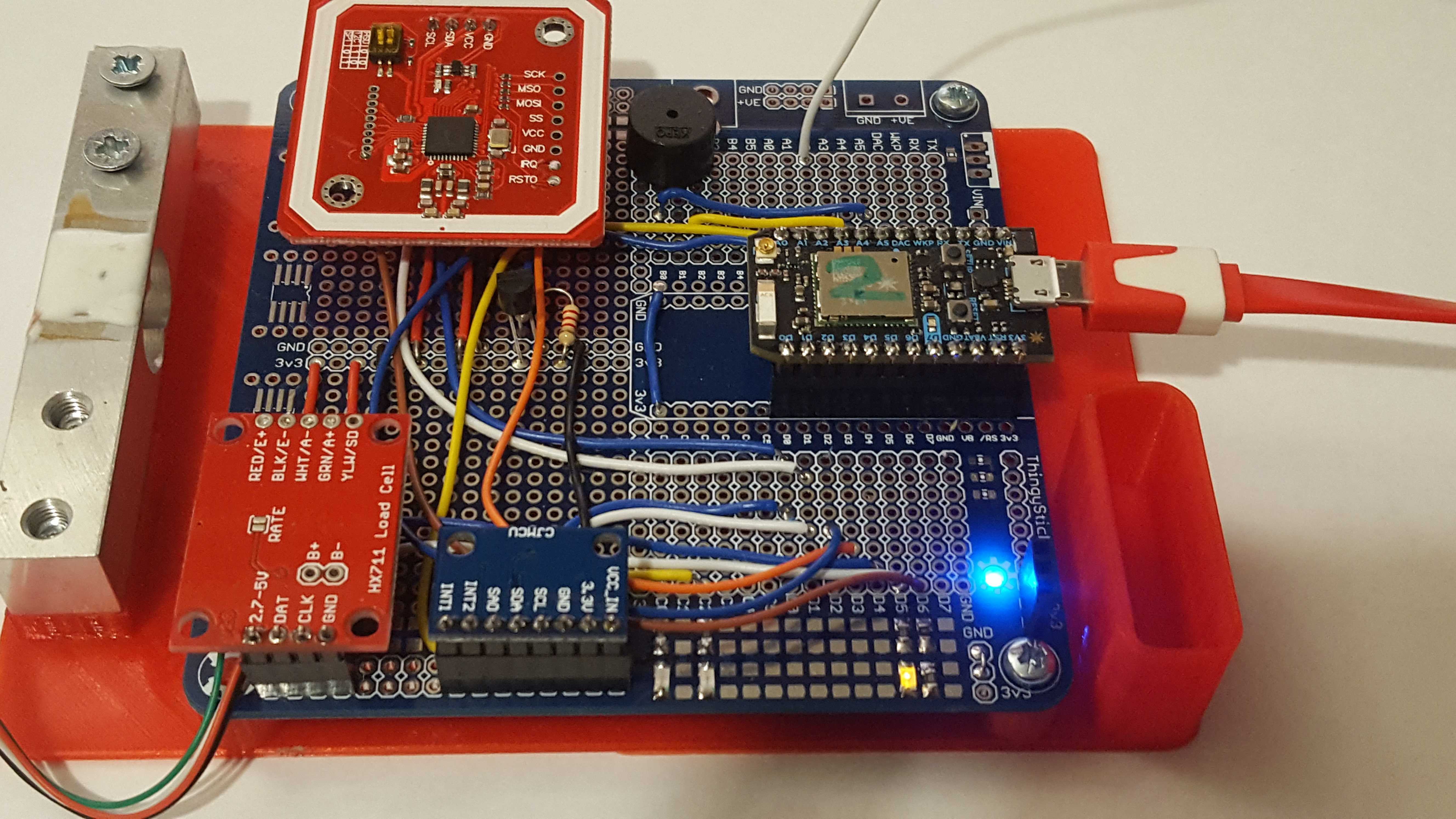
Prototyping
In addition to the PCB developed for the Reagent Tracker I also assembled a Prototype PCB to sit on the desk with components easily accessible by probes and a few extra LEDs to help view the state of the system. Whilst this makes it difficult to weight bottles, it is incredibly useful for debugging.
![]()
The blank prototype PCB will be available through my ThingySticks Tindie Store soon.
The 3D printed foot for this which holds the PCB, battery and the load cell is available in the files section or from the GitHub repository.
It's also possible to hack the V1.0 PCB and bodge on the appropriate sensors but it gets messy:
![]()
The electronics and PCB design are release under Creative Commons Share-Alike 4.0 License, many of Eagle parts and footprints and information on breakout board usage are from SparkFun used under the CC-SA-4.0 license. Thank you SparkFun!
-
3D Printed Case
06/07/2017 at 18:18 • 0 commentsDesign Considerations:
The starting point of this project was the case, I wanted something that a bottle of FormLabs resin could sit on (about 100mm diameter), or be dropped into when not in use to act as both storage and measurement system.
It had to accommodate a load cell and NFC reader to identity of the bottle, ideally be cylindrical to match a bottle. I wanted the bottle to have a NFC label stuck to the underneath, that makes it easy to align the tag with the reader, without having to rotate the bottle to align the tag.
The case also needs to support either a battery or a power connection of some kind.
The initial designed idea allowed for a NeoPixel ring to be embedded in the top half to show the user a clock style usage gauge however these are power hungry and blocked when the bottle is on the scales, so these have not been use further.
The scales are internet connected and no interaction is needed for normal operation other than placing the bottle on them and removing at an appropriate time. The user does not need to know the measured weight so no display is needed and only a single LED and buzzer are used to give feedback which greatly simplifies the case design.
The final design consideration was to make it drip proof. The top should either be a solid print or support a coating of epoxy to seal in any electronics, mounting hardware and anything else.
The load cell was easy, the type found on eBay rated at 5Kg are smaller than the bottle diameter so would fit without too many problems. The NFC readers on the other hand were more problematic. Their are a number on the market similar in design to the AdaFruit PN532 NFC Controller breakout board where the aerial is an extension of the PCB. To use these we would need to extend the top case to accommodate an oversized PCB sticking out the back, this starts to make the design look ugly and clumsy as well as difficult to seal.
Initially I tried the RC522 type readers from eBay, however these don't appear to support the NFC tag type (NTAG2) that is used by the stick on NFC tags (or at-least the ones I was able to buy easily). Fortunately I found that the PN532 NFC readers sold on eBay were a perfect size (less than 45mm x 45mm) so they would fit nicely underneath a bottle and they are also able to read the NTAG2 tags. As an added bonus they use the same controller as the AdaFruit board so I was able to use the driver developed by AdaFruit. More on the NFC side of things later.
Battery wise I planned on using a 3000mAh LiPol cell that comes with the Particle Photon power module and the Electron as I have a few of these to hand, again this would fit nicely to one side of the load cell within a diameter that worked for the bottle.
With the NFC board being smaller than the diameter of the design it would be easy to finish the print with a coat of epoxy resin to provide a drip proof top case.
Design Software:
Being a programmer I use OpenSCAD for most of my 3D designs, generally it works well for simple designs like this one and allows for parametric designs. OpenSCAD is open source, licensed under GPL 2.0.
The stl files are provided and are directly printable by most 3D printers so you don't need OpenSCAD to make the case.
Case Design:
Initially I went with a cylindrical design with a square section on the bottom half sticking out backwards to house the electronics. However as with nearly every design things change as you try them out and either don't work or present nicer ways to achieve the end result.
With the initial design it required 7 wires for the NFC reader and another 4 for the load cell, this very quickly got messy when trying to assemble the scales and was noticeable that those cables would exert strain on the upper half that may effect reliable measurements, additionally with the load cell and NFC being permanently connected to the top half, it made opening the case troublesome and risks the connections of the delicate load cell wires.
Typically when designing a 3D printed case you will look to have the two halves joining snugly, however the nature of the load cell is that it flexes very slightly with load being placed on it, likewise there will also be a small amount of movement with the 3D printed case so the design needed to allow space between the top and bottom to prevent these two contacting and effecting the measured weight.
I also wanted to protect the bottom half of the case with electronics inside it from drips of liquid when the bottles were being weight, so I elected for a skirt on the top half of the case, this fans outwards from the top and has a good clearance around the bottom half. Any drips from the bottle will flow down the skirt and onto the bench below.
Trying to create a skirt that went around a half square and half round base and looked nice didn't work so well which re-enforced the idea of a purely cylindrical design, this combined with the wiring issues pushed me down the route of a custom PCB that would allow the electronics to be mounted in the top half of the case, the NFC reader could then be connected by pins through the print to the PCB. The load cell would be mounted by 2 M4 machine screws to the top half, these are then covered in epoxy resin so the load cell is permanently attached to the top half. The PCB design was simple at this stage as a prof of concept and sent of for fabrication.
The PCB and electronics will be details in another log, but for now the design was a circular PCB just smaller than the diameter of the scales with a cutout for the load cell in the middle. Initially the load cell amplified PCB was still separate but it included the micro-controller (a Particle Photon), power input, connections for a possible NeoPixel ring, 4 pins for the NFC I2C and Power, the others are done by flying wires onto test pads to make alignment easier.
The top case then needed pads on the underneath to support the PCB.
The top side of the top half is designed with a cutout for the NFC PCB with 3 openings to the underside to connect to the PCB, two recessed M4 countersunk screws for the load cell, a border around the outside to allow this area to be filled with epoxy to make a nice level drip proof top, and then a raised back (or an all round cylinder) to finish it off nicely and help with bottle placement.
Whilst it would be possible to alter the design to print the top half up-side-down to give a nice finish on the top surface it would mean that we would have no lip for the epoxy poor and no back to the design, or we would end up with support material markings on the top surface which would look ugly in the most noticeable place.
Printing the top the correct way up means we need a lot of support material to fill the inside of the skirt until we get to the main body, however all of this will be hidden from sight and with a little clean-up doesn't effect the part, but it does waste a lot of filament and time.
For prototype designs or where most of the system is not visible it is possible to print without the skirt which drastically decreases the print time and makes it easier to get test wires in and out of the system.
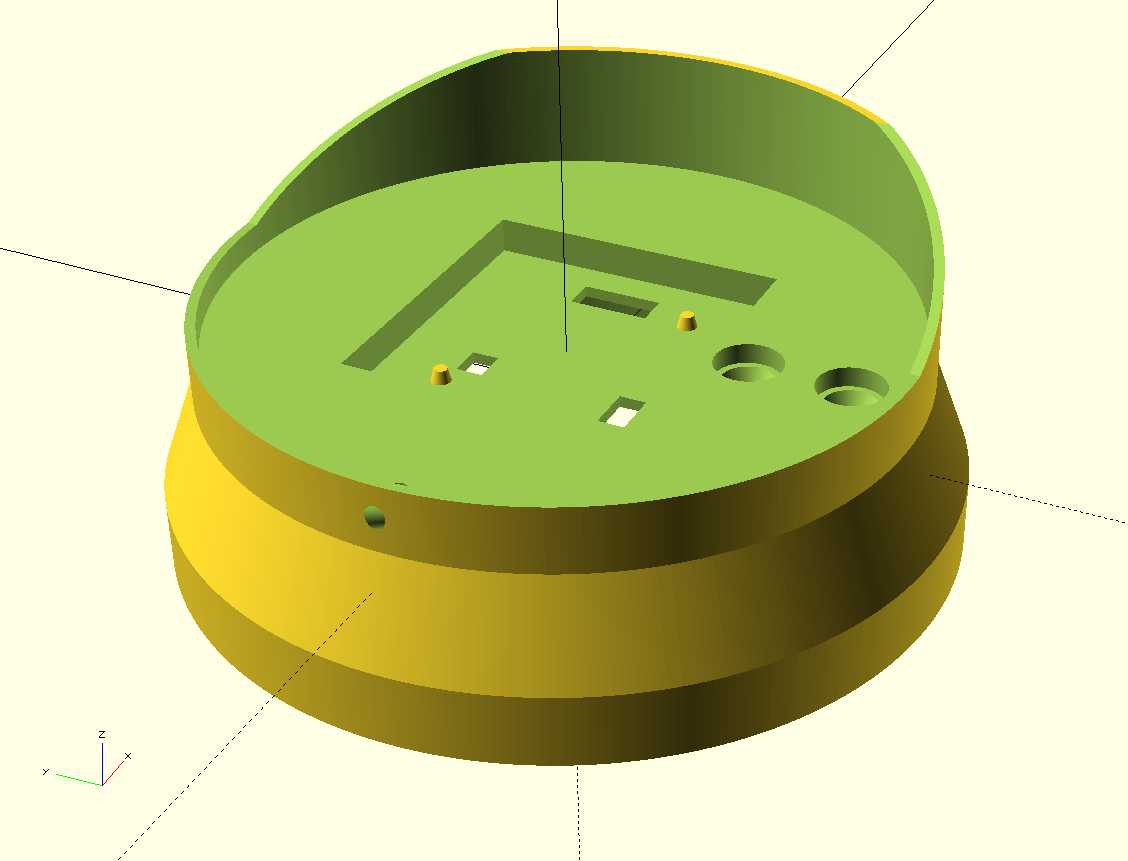
Top Half:
![]()
The file BottleBuddyTop.scad is the design for the upper half, the design can be customized with the following settings:
* bottleDiameter: Default of 100 (mm). This can be increased for larger bottles. However care should be taken not to make it too large as the forces on the load cell connection may make it wobbly or fragile. Also the LED alignment hole with the PCB will start to be in the wrong place.
* sliceTop: Default true. This creates the slice through the top of the cylinder that extends upwards and creates the small back raised section. With the is set to false a full (hollow) cylinder is used to contain the bottle which might be preferable if used as storage for the bottle as well.
* epoxyDepth: Default 4 (mm). This governs how deep the outer ridge is on the top to allow an epoxy coating to be poured on.
* skirtOption: Default 2. This generates version 2 of the skirt (a cylindrical skirt). Set this to 0 for no skirt for a quicker print, or 3 for a polygon style skirt. Version 1 no longer exists.
If you make changes, use OpenSCAD's Render option to create a full render and then export as .stl
Print using Cura:
I use most of the default options for Fast or Normal print with infill increased and support enabled.
- Layer Height: 0.15mm or 0.1mm
- Wall Thickness: 1.05mm
- Top/Bottom Thickness: 0.8mm
- Infill Density: 40%
- Print Speed 60mm/s
- Support: Enabled
- Build Plate Adhesion: Skirt
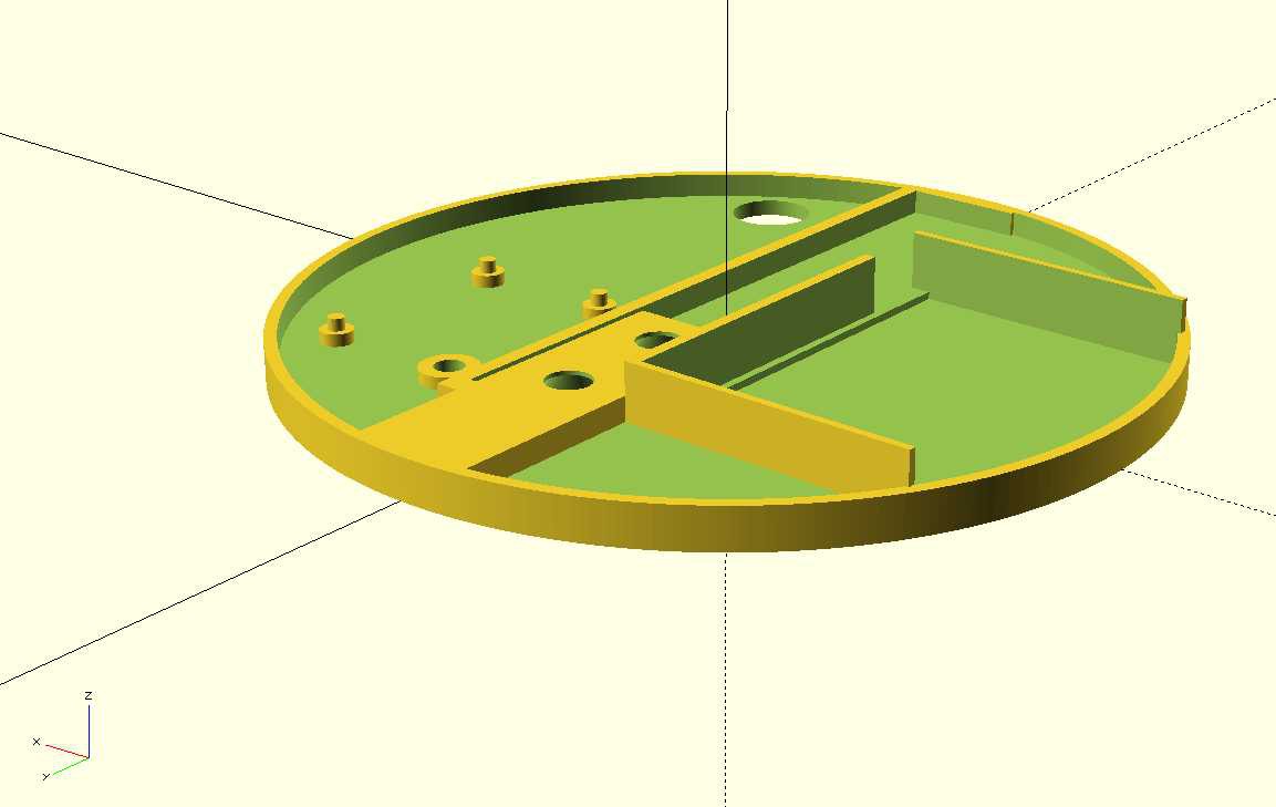
Bottom Half:
![]()
This is still work in progress and includes a mounting point for the load cell amplified PCB that will be removed with the next version of the main PCB, it also includes a battery compartment that is also unfinished.
Underneath it has 4 slightly raised sections for rubber feet to be attached, slightly recessed countersunk holes for M5 screws for the load cell and a hole for the power cable to exit (again a temporary measure for testing).
The file BottleBuddyBottom.scad is the design for the lower half, the design can be customized with the following settings:
wallHeight: Default 5 (mm). This is how height the outer wall is, it only needs to be tall enough to sit inside the top half skirt to hide the contents.
bottleDiameter: Default 100 (mm): Same option as is used for the top half. If you need a slightly larger design increase this. The load cell placement will not move so it will still align with the top half.
Print using Cura:
Again, I use most of the default options for Fast or Normal print with infill increased but support disabled for this half.
- Layer Height: 0.15mm or 0.1mm
- Wall Thickness: 1.05mm
- Top/Bottom Thickness: 0.8mm
- Infill Density: 40%
- Print Speed 60mm/s
- Support: Disabled
- Build Plate Adhesion: Skirt (You may prefer Brim if you get warping)
Reagent Tracker
Track reagent usage and get timely notifications to re-order.