polyfractal
-
Light engine teardown: redux
06/20/2017 at 15:20 • 0 comments![]()
I've been avoiding this step, but I think it's time: I need to replace the projector's LEDs with my 405nm laser. So time to open the projector back up and start dissecting it again.
But first, some photos of the projector! I realized I hadn't posted any photos of the projector while mostly-assembled. So before I destroy it irrevocably, here are some photos of the guts.
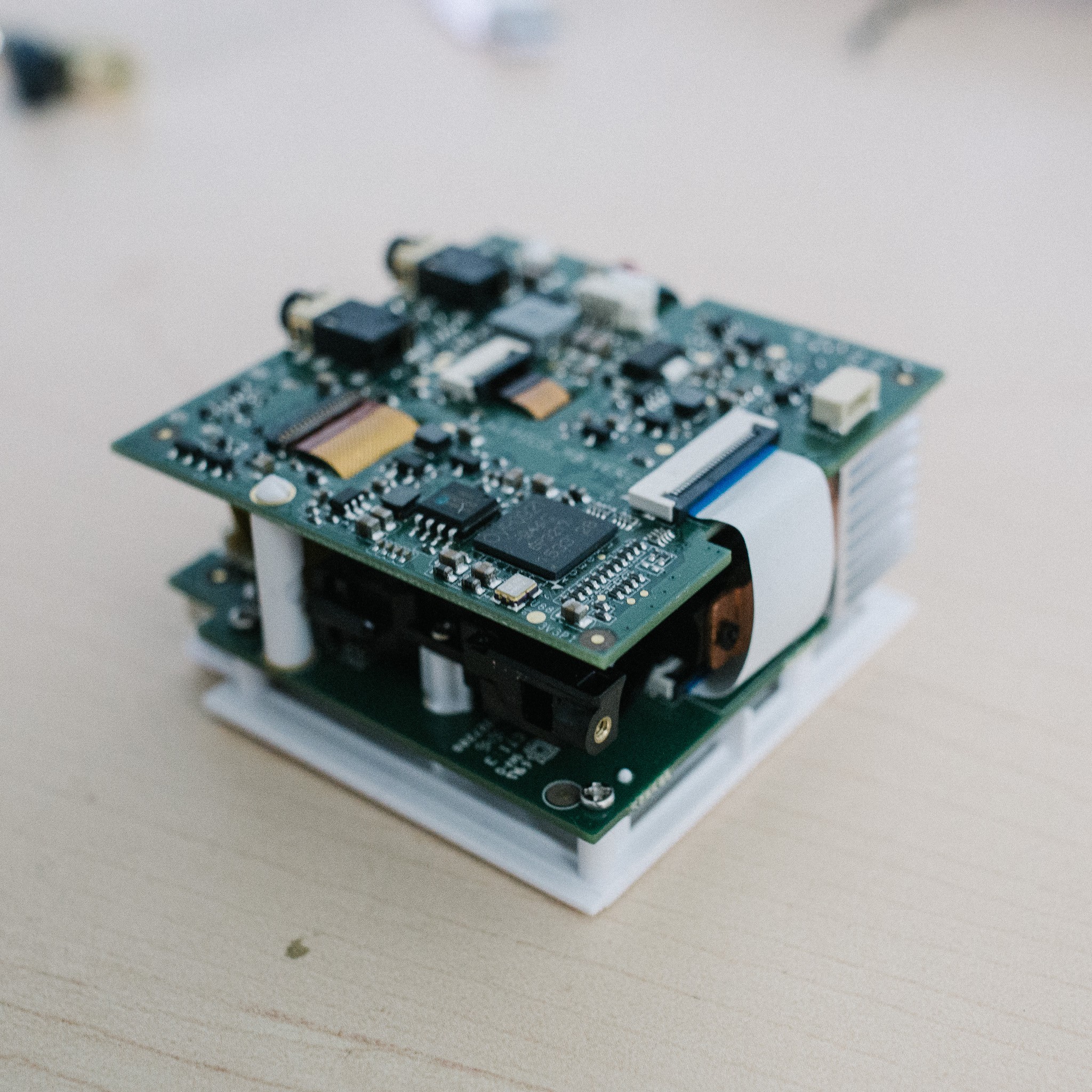
Isometric front view. The light-engine is sandwiched between two PCBs; it's the little black device peeking out from under the corner.
![]()
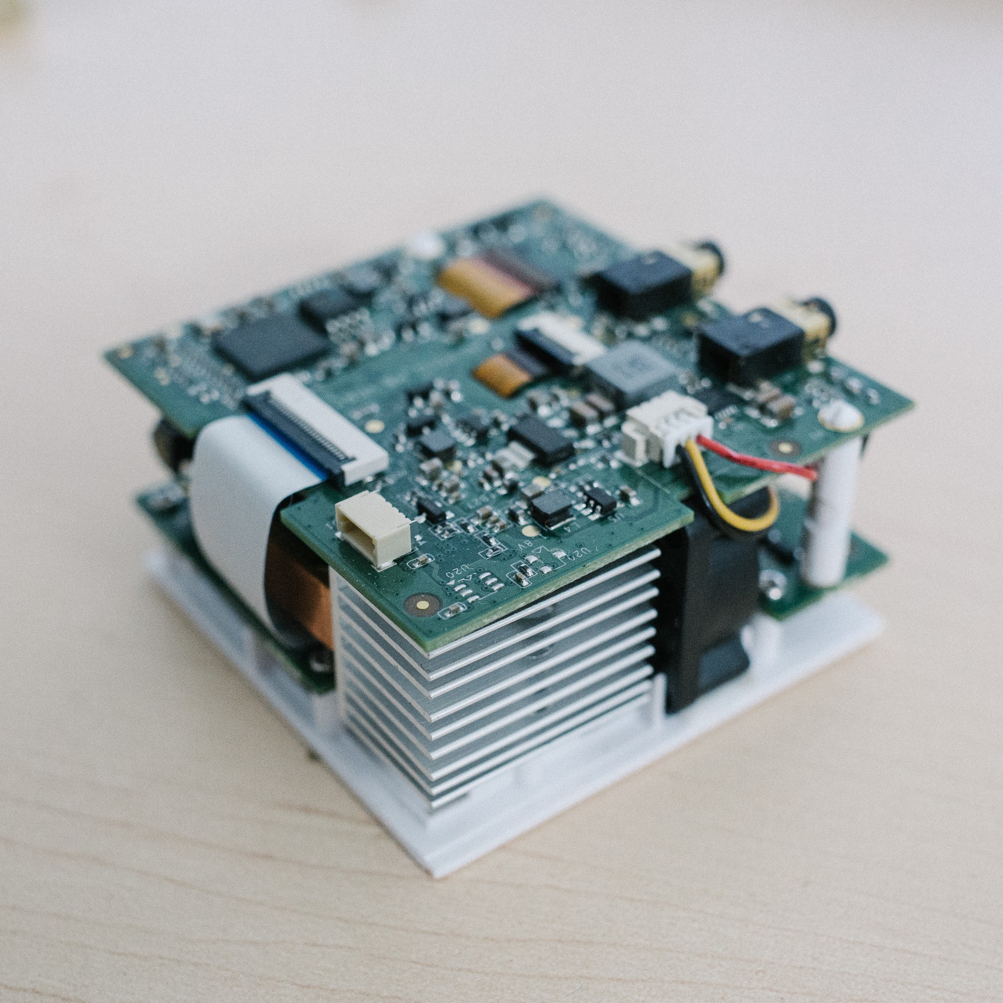
Other side. The aluminum heatsink is attached to a copper heat-spreader, which is in turn attached to the LEDs. The little black square is a tiny fan to cool the heatsink.
![]()
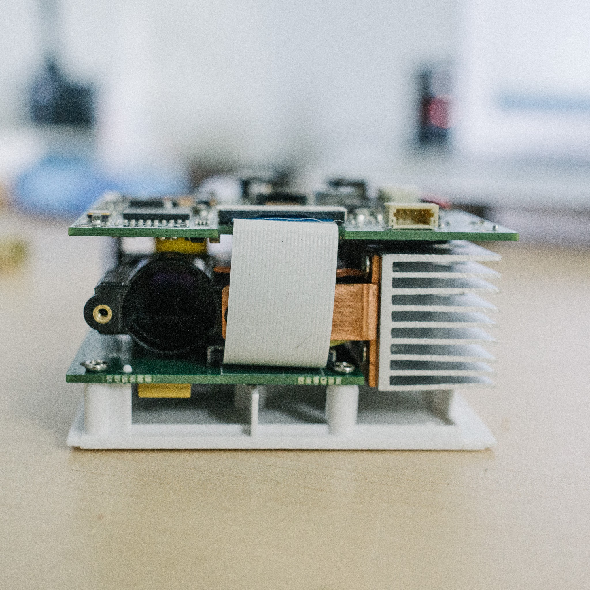
Front view, showing the projector output and heatsink. The ribbon cable connects the two boards together. All the projector logic/control appears to be on the top board, while the bottom board deals with IO (usb, HDMI, etc).
![]()
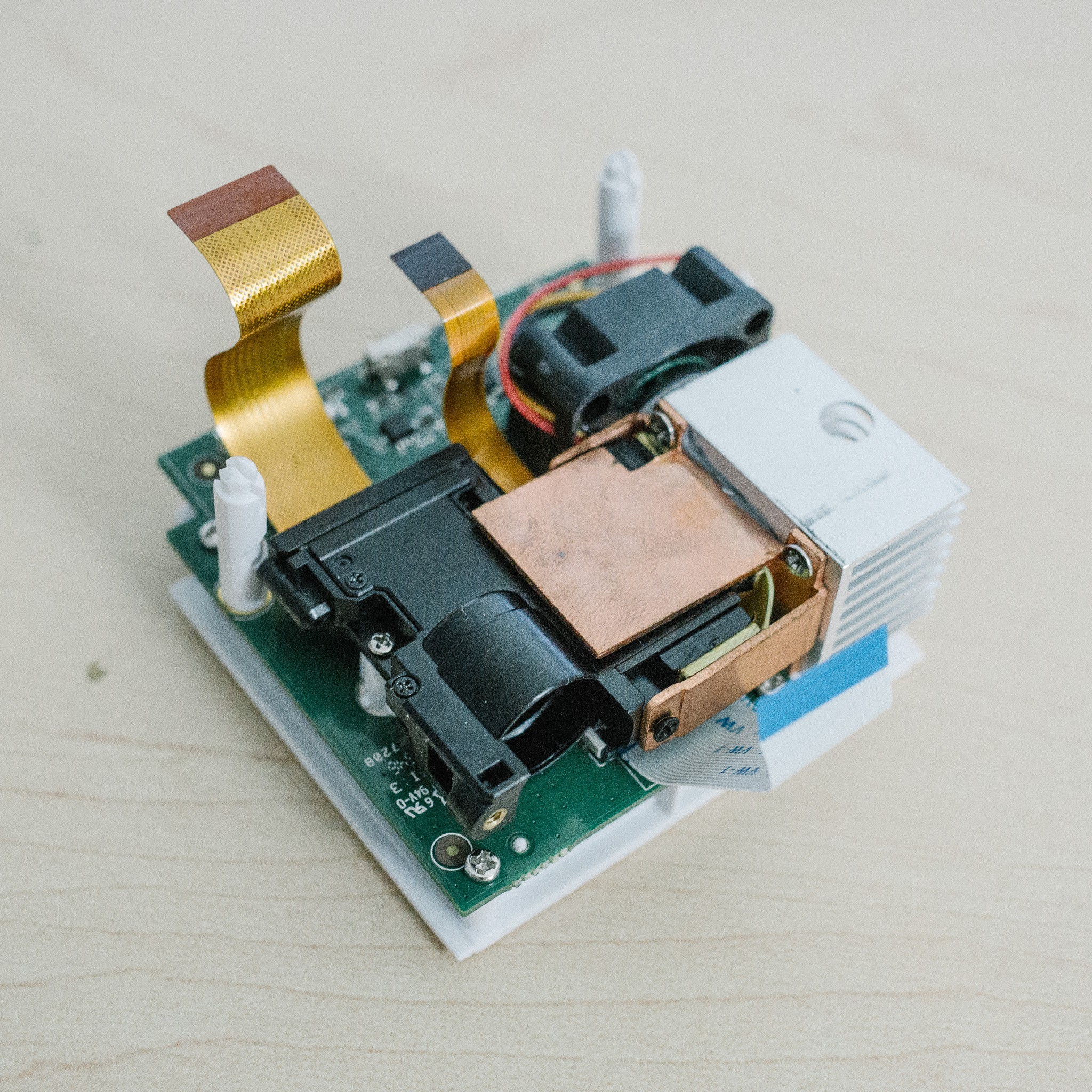
The guts, minus the top PCB. You can see the heatsink situation here a lot clearer. The wide ribbon cable controls the LCoS while the narrower cable controls the three LEDs.
![]()
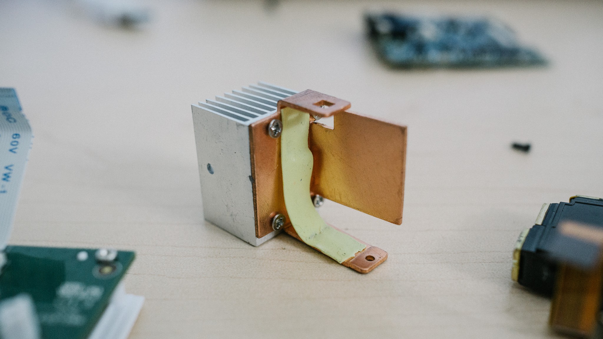
And the heatsink in isolation. The copper spreader wraps around the light-engine and makes contact with the three LEDs. A thin strip of thermal "tape" provides the heat transfer from LED to heatsink, presumably to allow a less-precise fitting and manufacturing tolerances.
![]()
Starting to destroy things
Ok, now is the part where I start to permanently remove components. I've been avoiding this because, frankly, I don't feel like buying another projector if I irreversibly ruin an important component.
But what're you going to do? The current setup isn't gonna work, so time to start disassembling :)
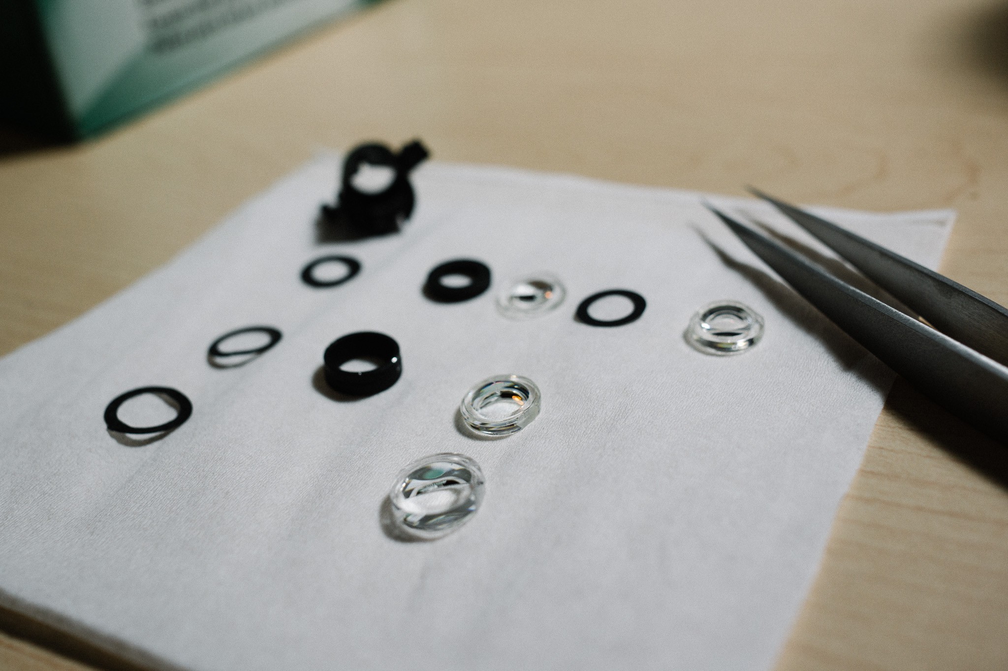
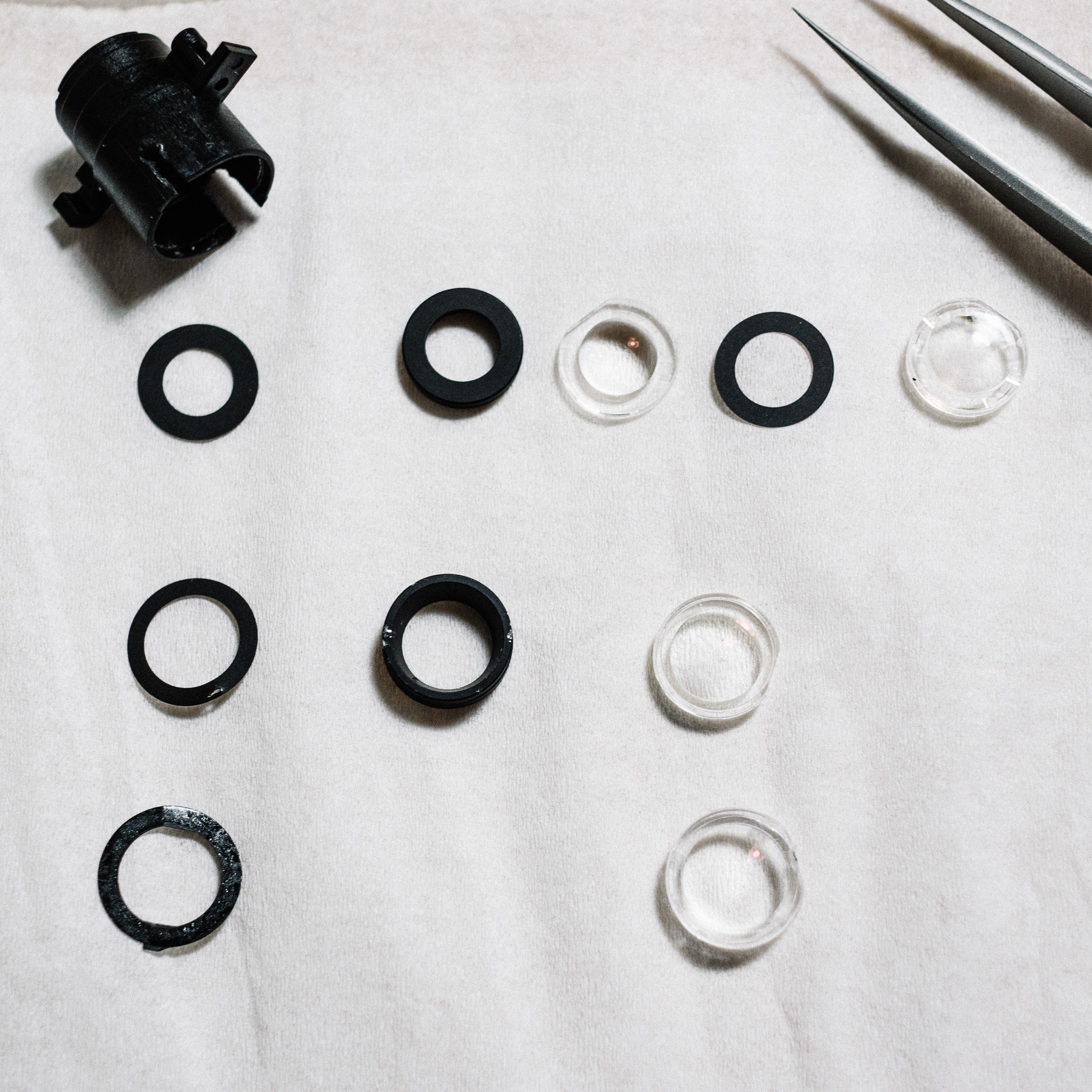
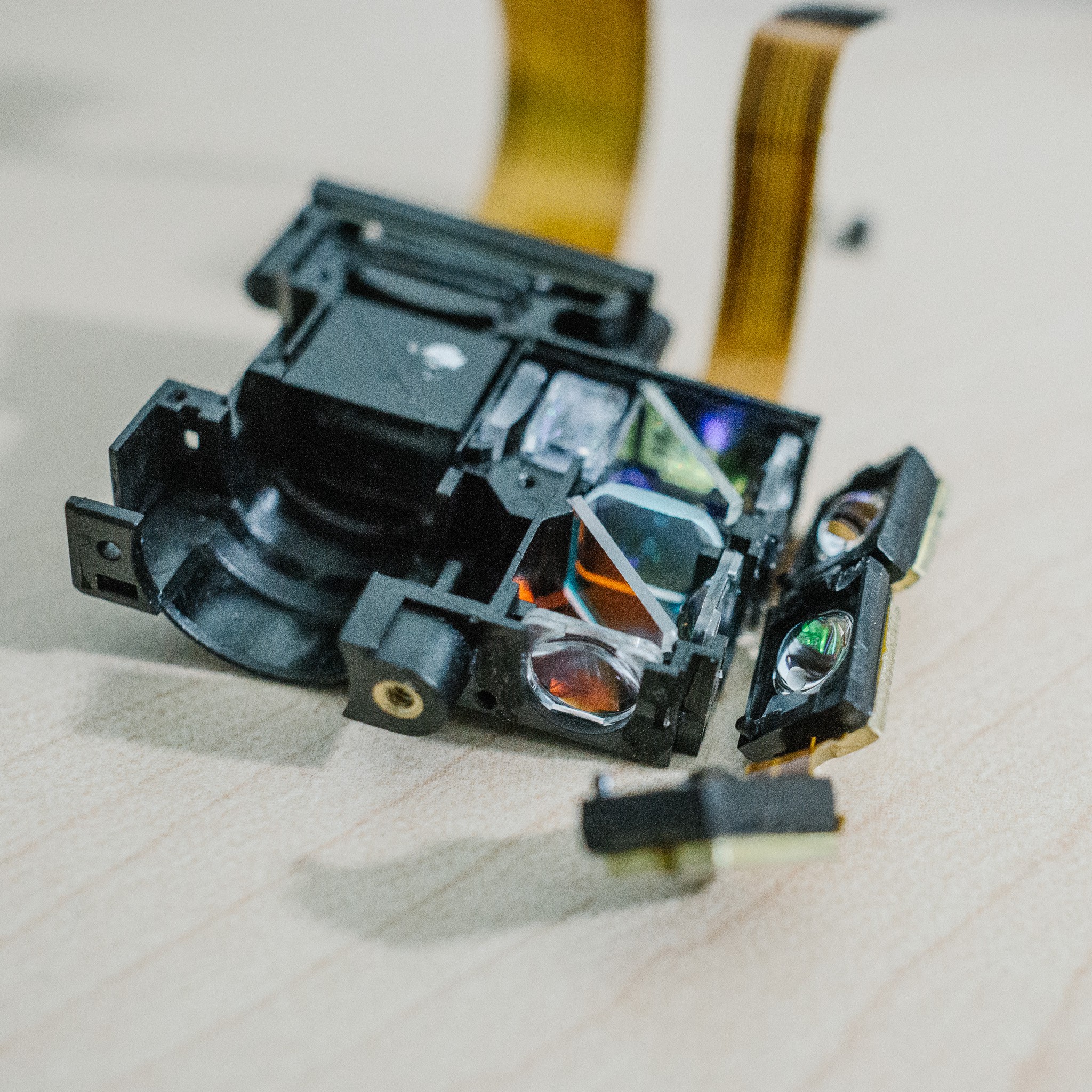
Below you can see the three LEDs which have been pried off the housing. They snap-fit into the main body and were held with a small blob of glue. Each LED has an integral lens, which projects into condenser lens on the light-engine body. A thin ribbon cable snakes between all three LEDs to provide power. And each LED has a small metal plate attached as a heatsink, which almost looks like brass?
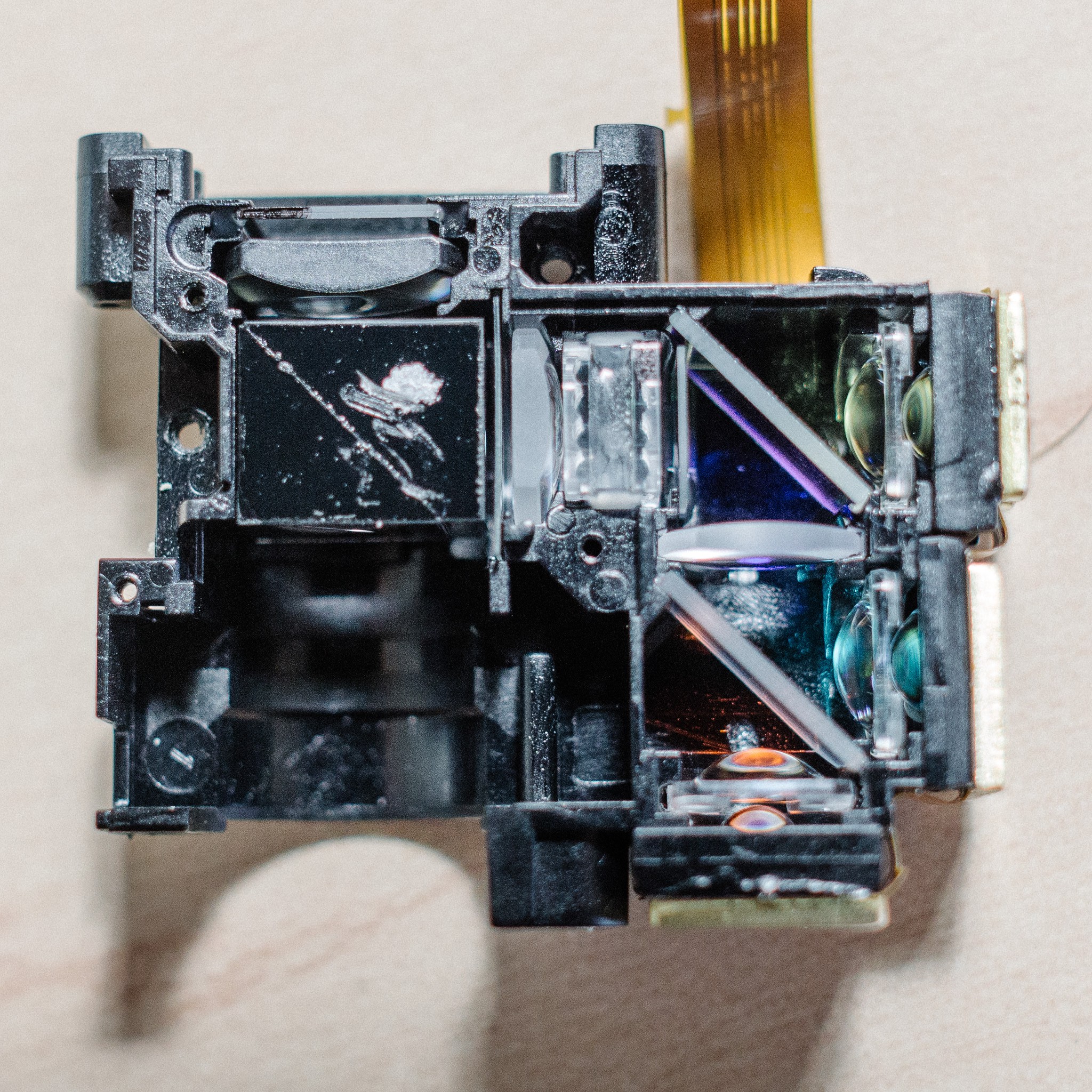
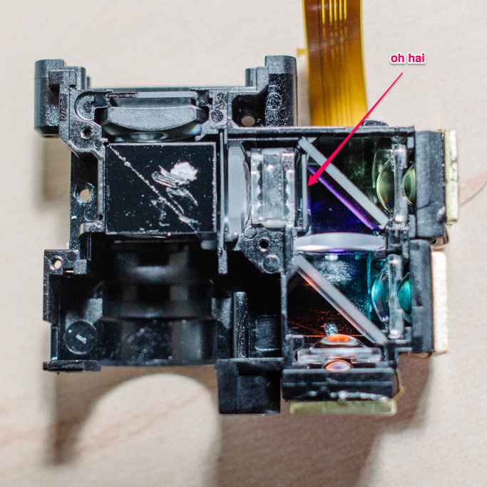
Turn your attention to those angled glass plates. I first assumed they were just simple beam-splitters, but it turns out they are dichroic mirrors. E.g. each mirror reflects a certain band of wavelengths, and transmits the rest of the light. I'm assuming this was done to clean up the spectral emission lines from each LED.![]()
For example, maybe their Red LED put out a bit too much green light, which would muddy up the final image. The dichroic mirrors allow them to only allow "red" to pass when the red LED is illuminated, avoiding cross-contamination.
That top mirror is the "blue" mirror, and allowed bluish wavelengths to pass. When shining my 405nm (violet colored) laser through it, a small amount of blue light was projected. It appeared that the mirror was cutting some or all of the 405nm wavelength that I was interested in.
So, out it came! The mirror is super fragile, and the coating flakes very easily. I scratched the corners while trying to remove it.
![]()
Unfortunately, this didn't seem to help much. A bit more light was passing through, but still greatly attenuated.
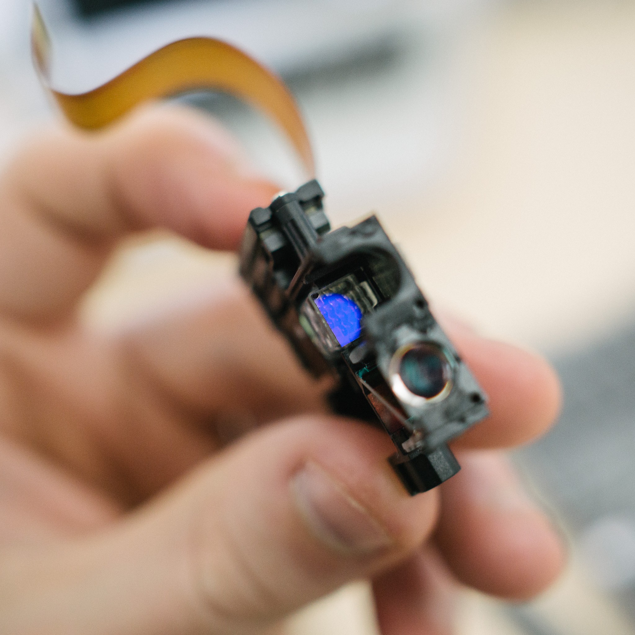
Then I noticed this little guy:
![]()
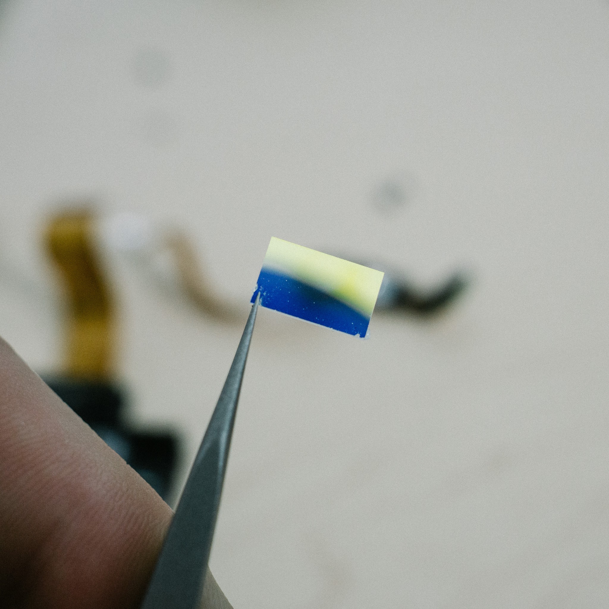
At first I thought it might be a polarizer, but I think that's later in the optic train (right after the microlenses and PCX, before the cube beamsplitter). When studying it, I noticed that if you caught the light just right, the lens reflected a bluish color:
Aha! I bet that's a UV filter. Which is exactly what I don't want :)![]()
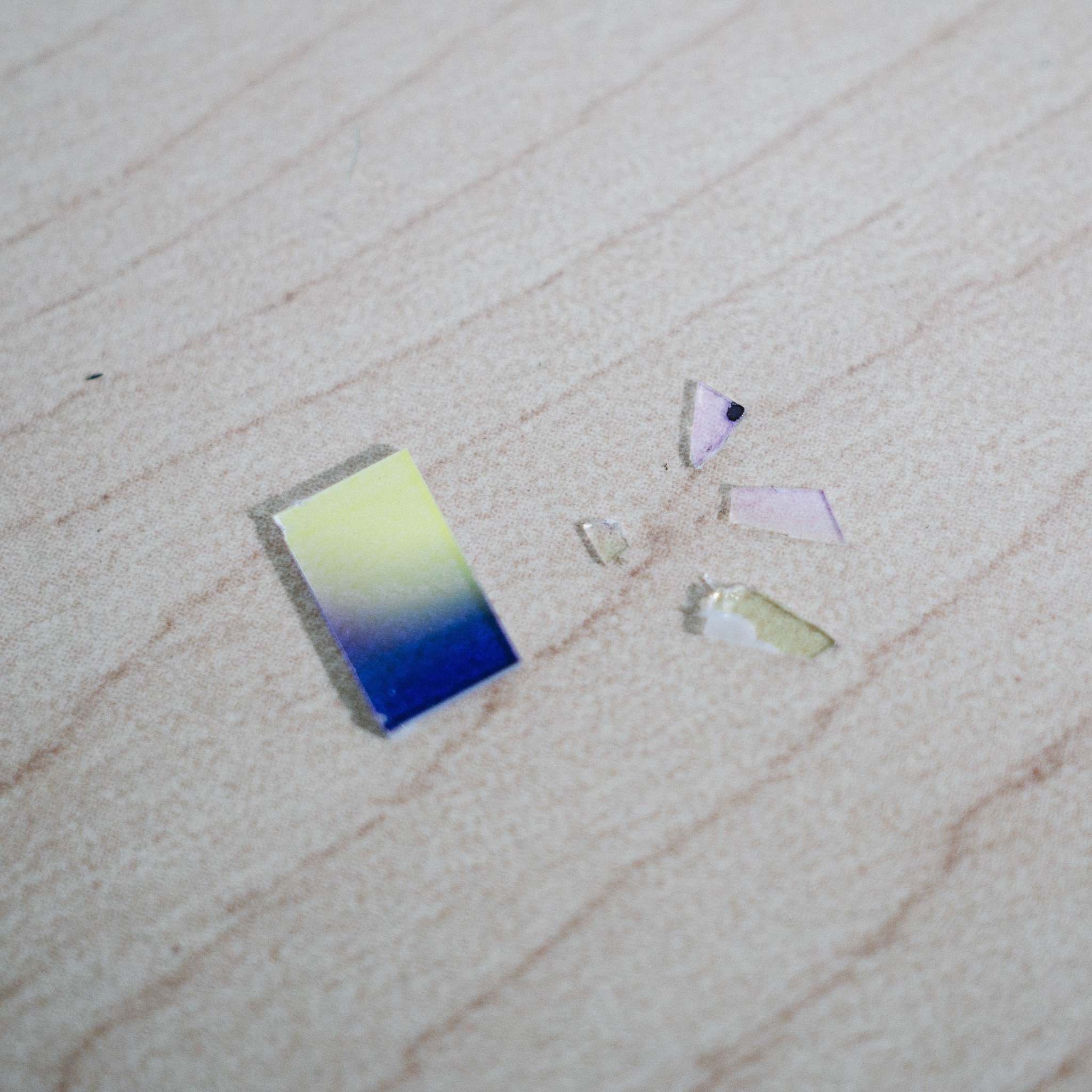
Out that came too. Unfortunately this filter was very thin, and glued in quite well. So it broke into a bunch of pieces while being removed :(
![]() After removing that filter, my laser projects cleanly through the rest of the optical stack and doesn't appear to be attenuated anywhere in the process. Encouraging!
After removing that filter, my laser projects cleanly through the rest of the optical stack and doesn't appear to be attenuated anywhere in the process. Encouraging!Moving Forward
So that's where I'm at presently. There are two directions I can pursue, still trying to decide:
- Design an enclosure to hold the light-engine body, laser, PCBs and microscope objective.
- Pull all the components out of the light-engine, design a unified body to hold all the components
The first option is appealing because many of the optics are already nicely aligned and fixed in place. I just need to design a body which aligns the rest of the external components to the existing light-engine. It has the downside of having to work around the geometry of the projector layout, which is no longer really needed.
The second option is appealing because I can streamline the optic train into a single print, remove unnecessary cruft and simplify everything (potentially removing some of those PCX lenses in the process). The downside is that I need to measure all the critical dimensions, design a much more complicated print and ensure that everything is aligned nicely.
I'm leaning towards Option #2 atm. More work up-front, but likely easier to deal with in the future. We'll see.
-
In search of a better photoresist
06/19/2017 at 04:07 • 0 commentsNot much to report from this last week, unfortunately. I printed a test enclosure for the lenses and a slide holder, then proceeded to test different exposure times with the photoresist.
The goal was to find the shortest time on the projector so that I could evaluate if the projector is sufficient, or if I need to start working on integrating the laser.
It was all sidetracked by problems with the photoresist. Or rather, developing the resist. Many consumer resists are developed in an alkaline solution, ranging from the relatively mild sodium carbonate through sodium metasilicate and ending at potassium or sodium hydroxide.
I assumed this random photoresist from China would be similar. I assumed incorrectly :)
Alkaline solutions do appear to loosen the resist, and allow it to slough off in big sheets when agitated manually. But the resist doesn't dissolve, and doesn't maintain any reasonable resolution.
I've tried several different concentrations of sodium carbonate, metasilicate and NaOH. I've tried manually agitating, sloshing, dunking in alternating developer/distilled water baths, pipetting forcefully. I even tried a few where the solution was heated to ~70C. No dice.
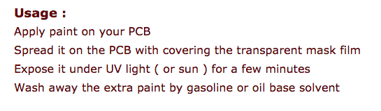
The eBay listing is not terrible helpful either:
![]()
Organic solvents do, indeed, remove uncured resist very well. Acetone will aggressively dissolve it, as will less-volatile solvents like lacquer thinner and MEK. The problem is that they the cured sections are visibly disturbed by the solvent. When viewed under a microscope, the cured resist becomes somewhat clumpy, with frayed edges and pieces starting to lift off.
This appears somewhat standard for negative resists. The literature says that the semiconductor industry moved away from negative resists in part because of their lower resolution. Cured resist remains somewhat soluble in the developer, which causes some accidental removal as well as "bloating" the cured section.
So I may just be seeing an extreme version (due to inferior quality resist) of what the industry already knows. In any case, I doubt I can achieve any kind of resolution with an organic solvent as developer and this particular resist.
Moving forward
So I'm back to hunting for a better resist. I've continued enquiring with smaller semiconductor supply houses if I can get a small order / sample of resist, but no luck so far.
In the mean time, I have two more resists on the way:
- ER-71, a negative photoresist from Datak.
- PC-197, a positive novolac photoresist from Injectorall
I also purchased the "official" developer for each resist, just to rule out any variables. I can experiment with recreating the developers later if it works. I'm particularly excited for the PC-197 because it's a positive resist that appears to be chemically similar to semiconductor-grade resists (e.g. probably a DNQ-novolac resin). It is, unfortunately, very expensive.
So that's where I'm at. While waiting for new supplies to arrive, I think I'm going to start modeling out an enclosure that incorporates the laser. The projector light seems sufficient to develop, but only after long exposure times (15+ min).
-
First photoresist development test
06/12/2017 at 02:15 • 0 comments![]()
I'm currently waiting on a shipment of chemicals to arrive so I can develop my photoresist-coated slides. But I just couldn't resist (har har har) doing a quick test to see if the projector and/or laser put out enough power to actually develop the resist.
Tl;dr: they do :)
The laser I have is a cheap 25mw 405nm laser with a "focusable" point. I bought it for $15 on amazon. The package says "4-5V, <65mW", and I've read online that laser diodes prefer constant current. I think it's because constant voltage can lead to runaway thermal problems (e.g. the diode heats up which causes resistance to drop, which then draws more current, heats up more, draws more current, etc). But I only quickly skimmed the material so that may be wrong.
In any case, the diode is probably way out of spec. At <65mW the diode doesn't even light up. It seems to like 150-300mW and under CC it usually pulls ~1.5V. I have no idea why/what's going on. I also have no way of testing the actual laser power output, and nothing to compare against, so who knows. :)
Obligatory disclaimer: If you work with lasers, wear properly rated laser goggles! Short wavelengths are particularly troublesome, since our eyes aren't very sensitive to short wavelengths. E.g. a 25mw green laser will look much brighter than a 25mw violet laser.
This can be dangerous because your body's natural defense mechanism is to blink when dangerously bright light hits it. But since your eye is less sensitive to short wavelengths, the blink response is delayed or entirely absent... despite the fact that the same amount of radiation is hitting your retina.
So be safe, wear safety goggles!
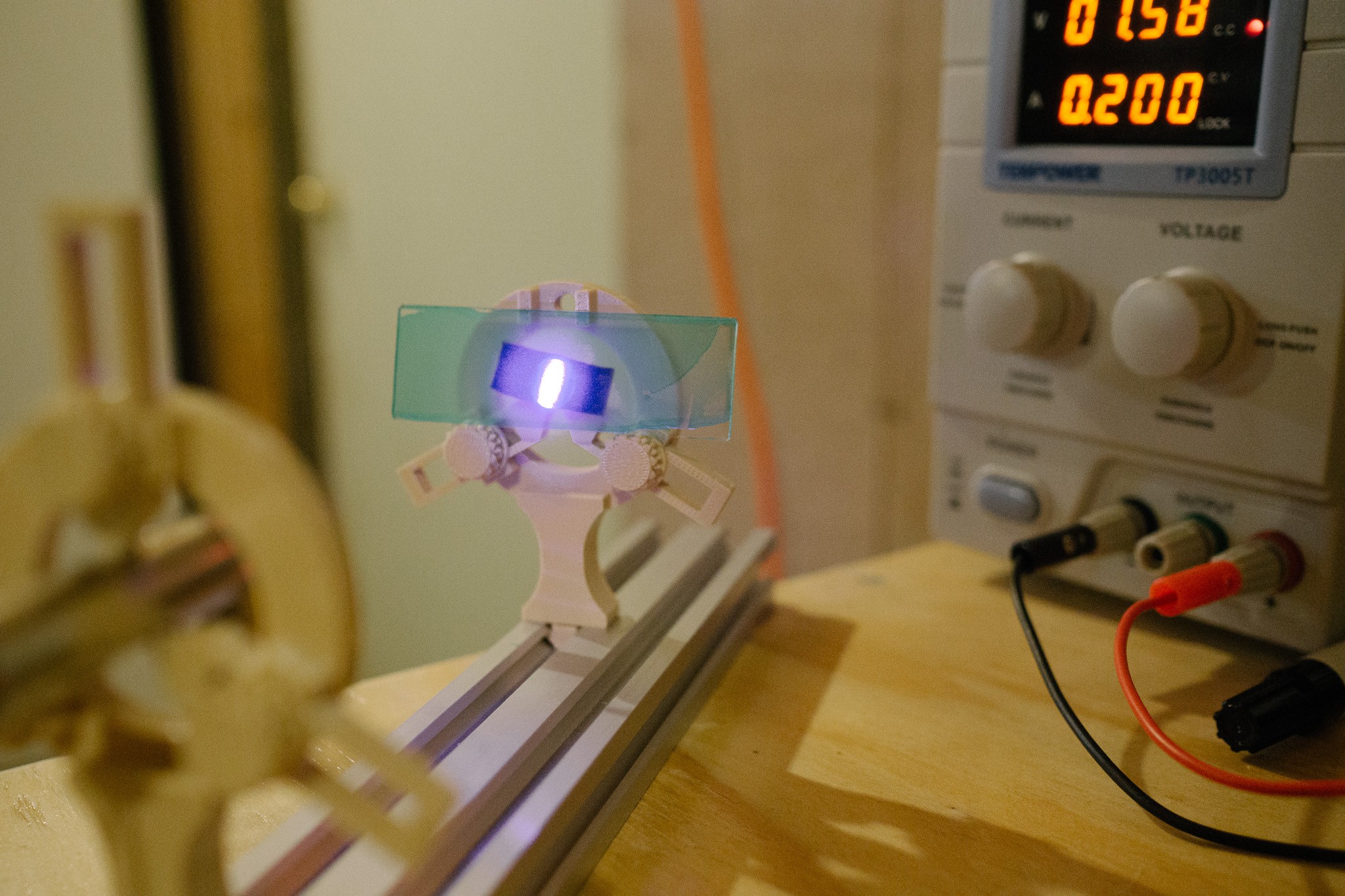
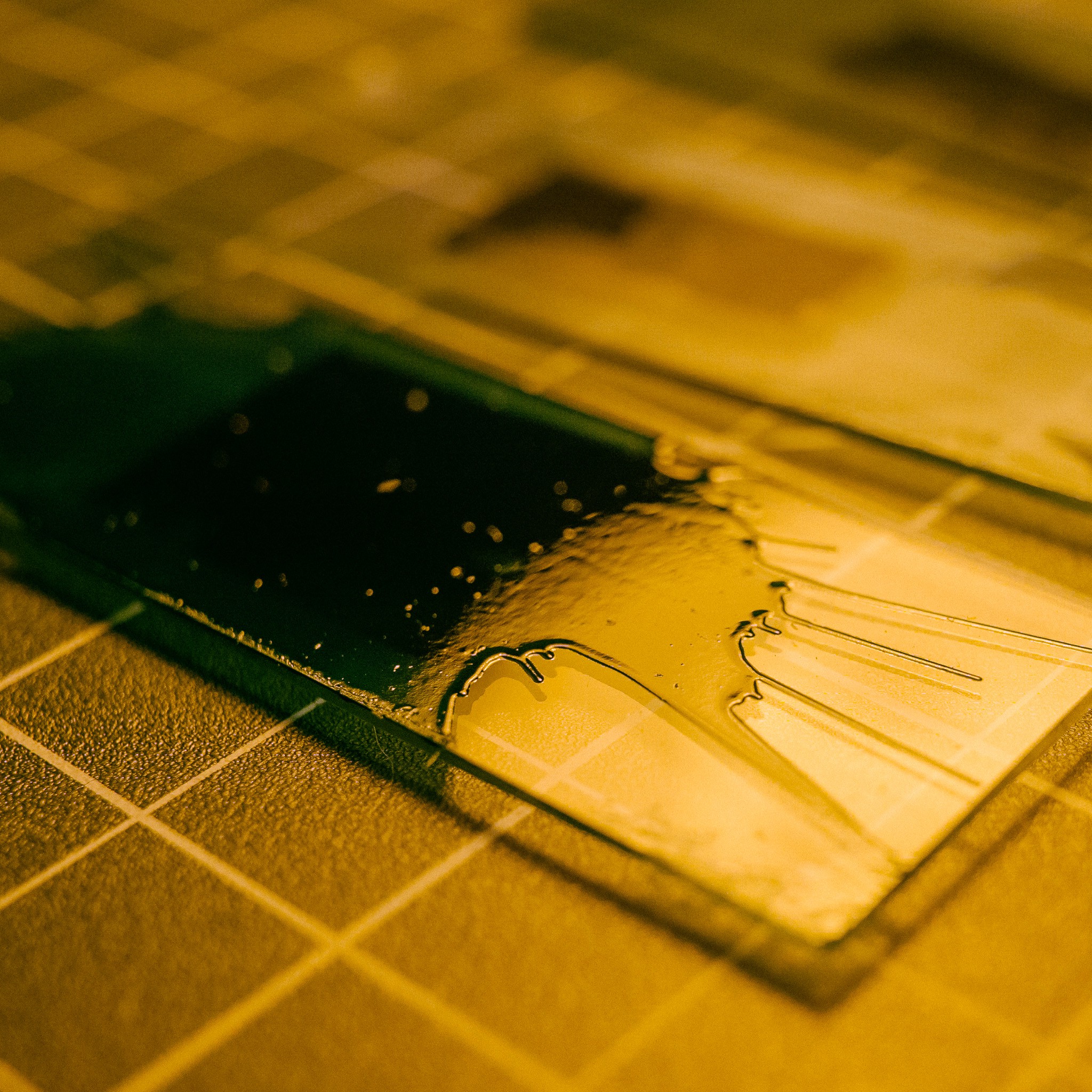
For a crude test, I took one of the spin-coated slides and set it in the path of the laser and let it expose for ~5min at low power. Then I cranked the laser up a bit, moved the slide and repeated twice more.
At low power, you can see that the laser leaves a very faint violet halo (and a poorly collimated "point" which looks more like a line... need to see if the laser has collimation grub screws). The dot was only slightly visible under the yellow work-light, and completely blocked by my goggles.![]()
At higher power, you could just make out the dot through the goggles, and it completely over-saturated my camera. The diffuse glow from the laser is also quite large.![]()
As I mentioned at the top, I don't have the proper chemicals for developing the resist (yet), but I did a quick test with acetone just to see. Acetone will remove the undeveloped photoresist, although I think it also takes off some of the developed stuff too unless you are really gentle.
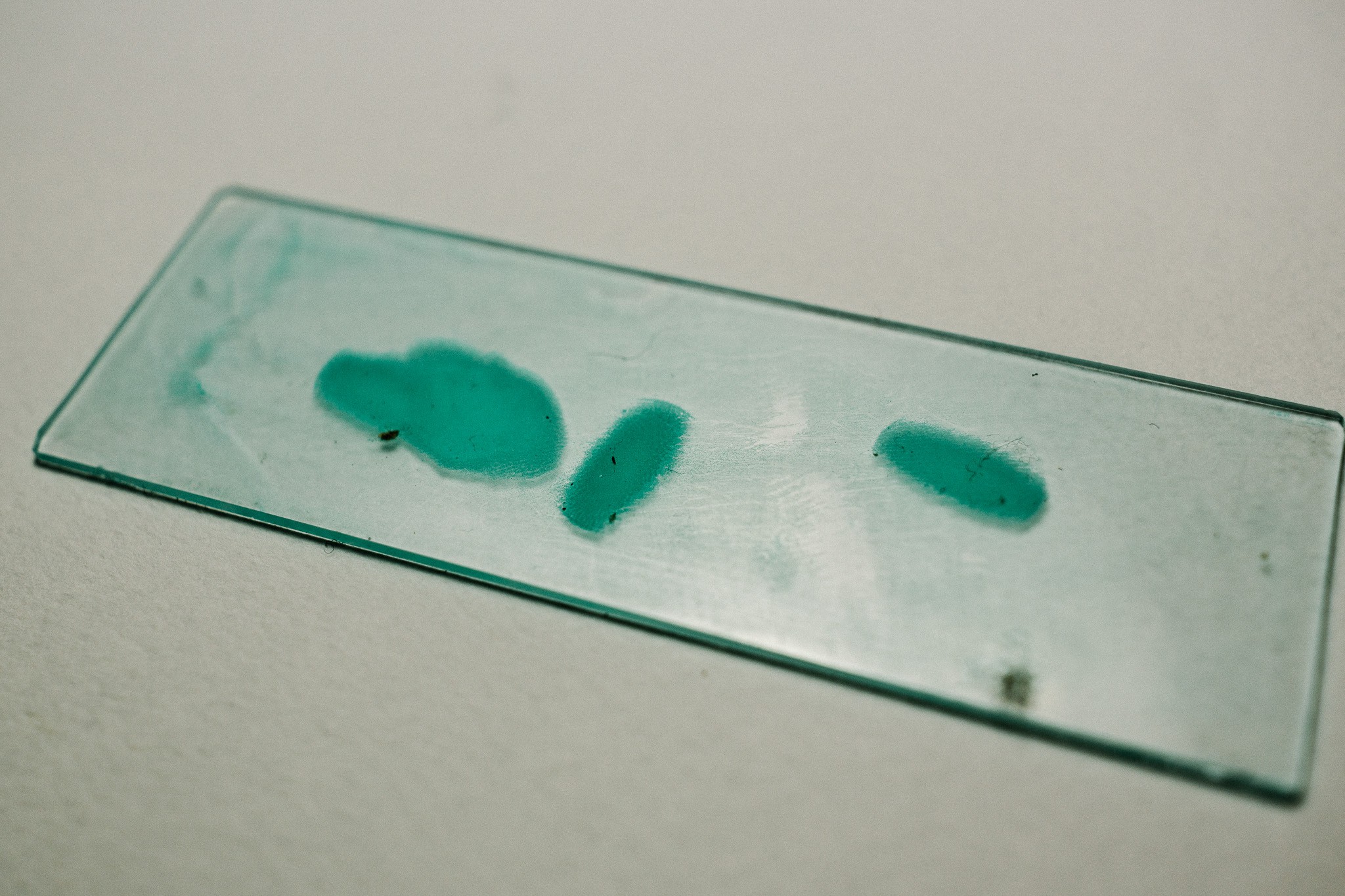
Still, the results were encouraging!
Three spots from three different tests!![]()
I hoped/expected the laser would work, but I was much less sure about the projector light since the 405nm component is likely quite a bit weaker. But easy enough to test out!
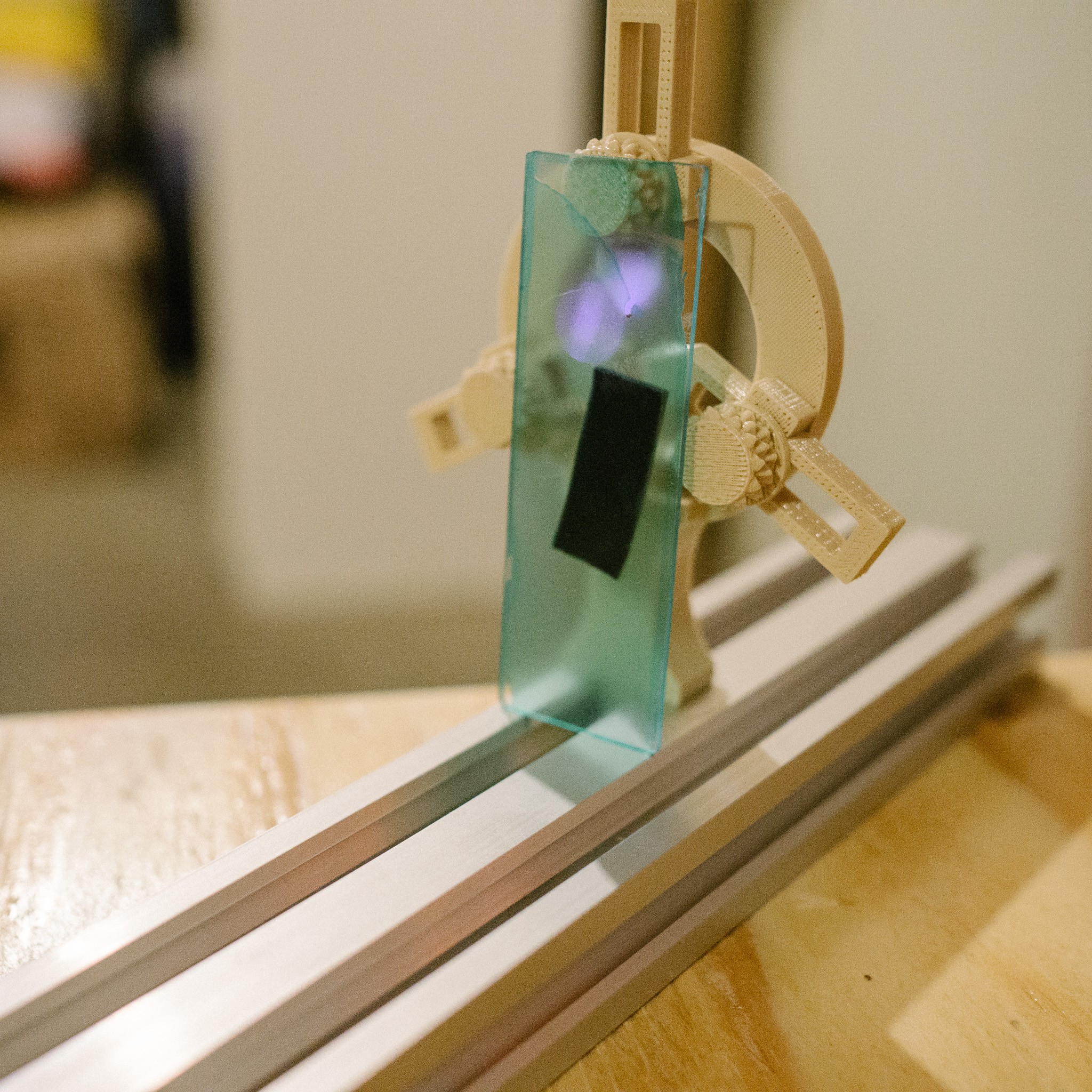
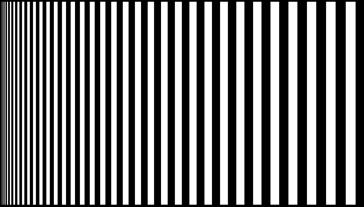
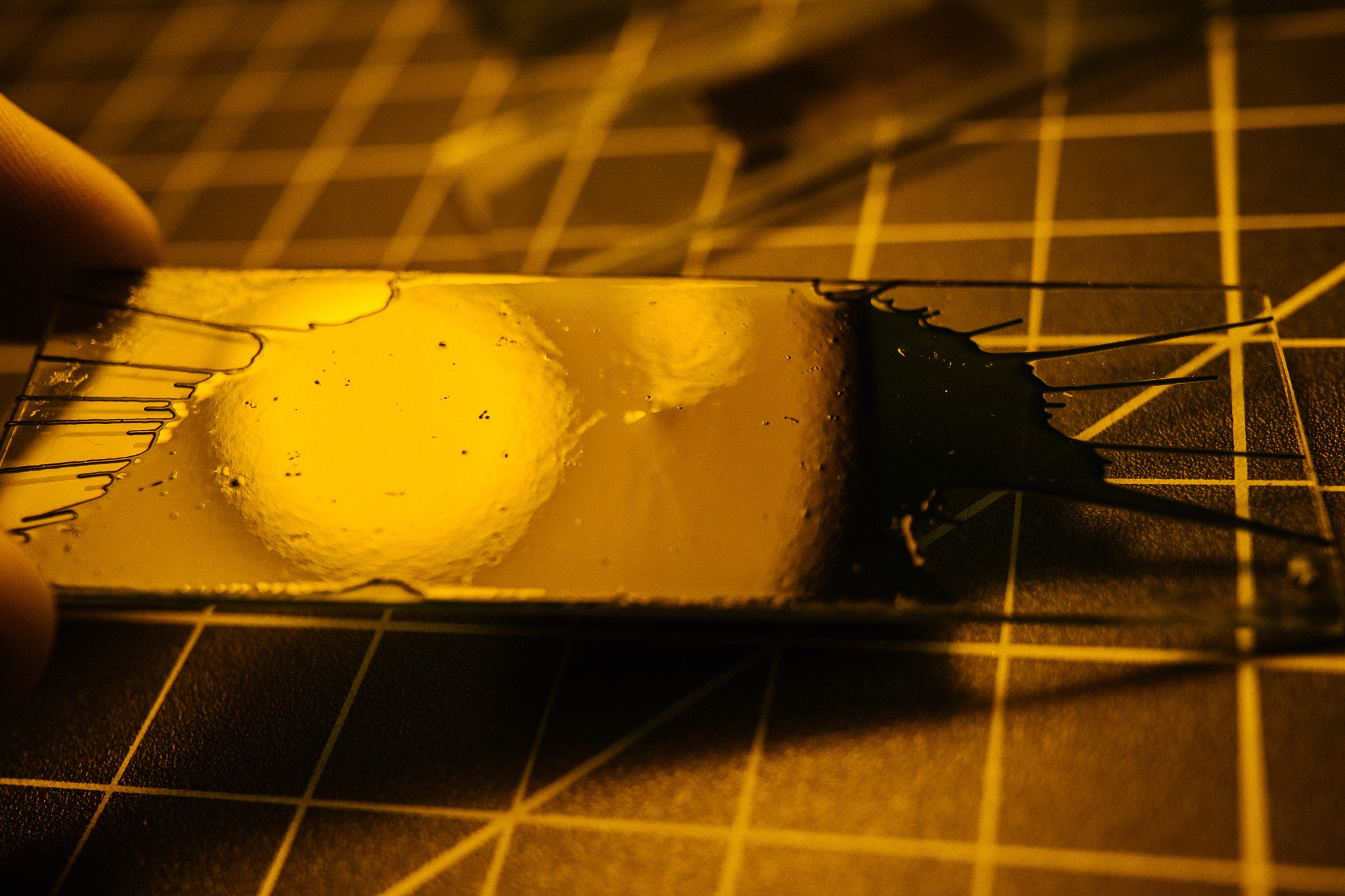
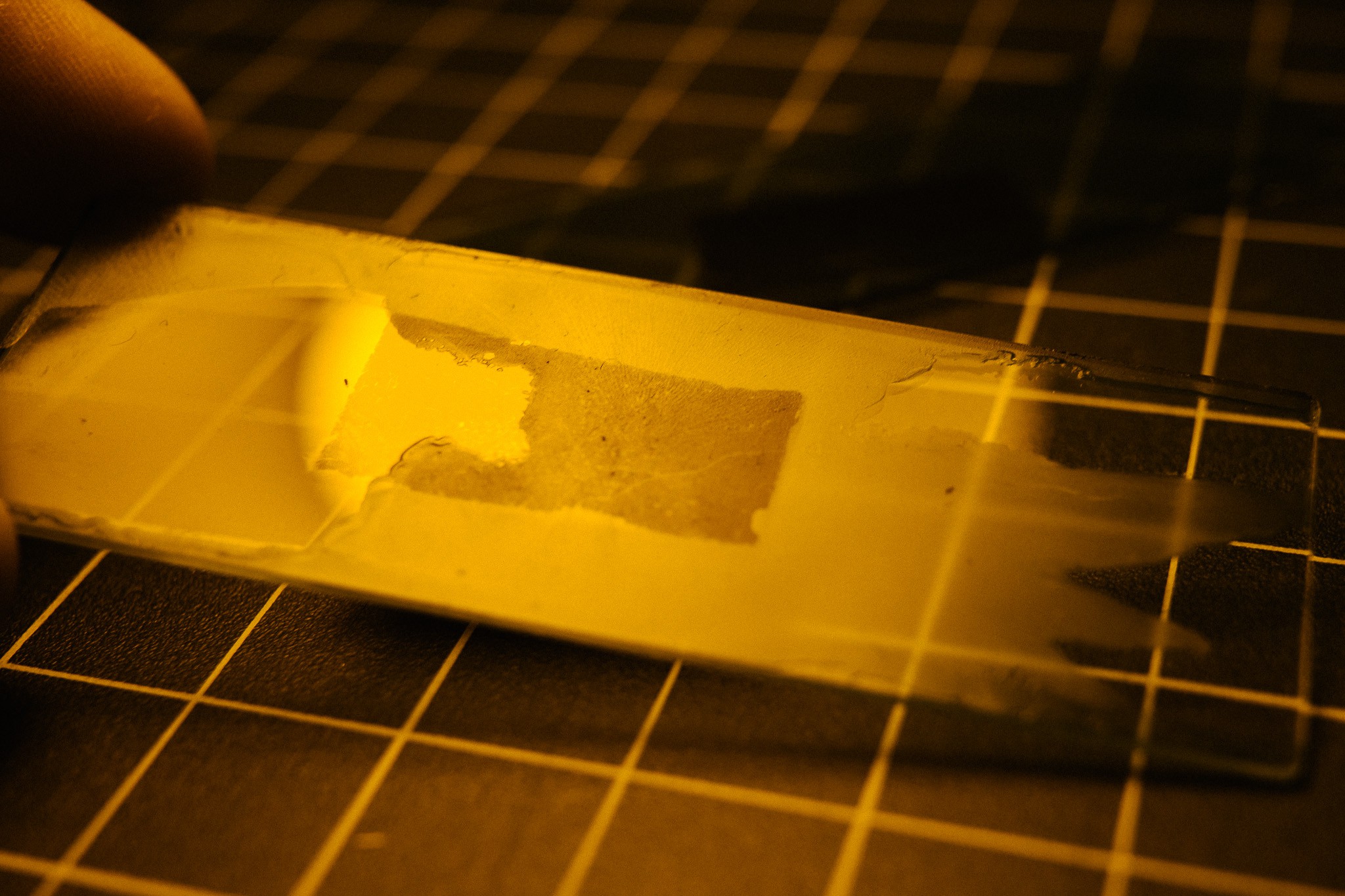
I placed a coated slide in front of the DIY objective and let it expose in two tests (20min and 40min). The test pattern was a series of alternating black/white lines that grow increasingly larger. The idea was to see at which point the resist stopped resolving detail, assuming it was even capable of exposing the resist.![]()
![]()
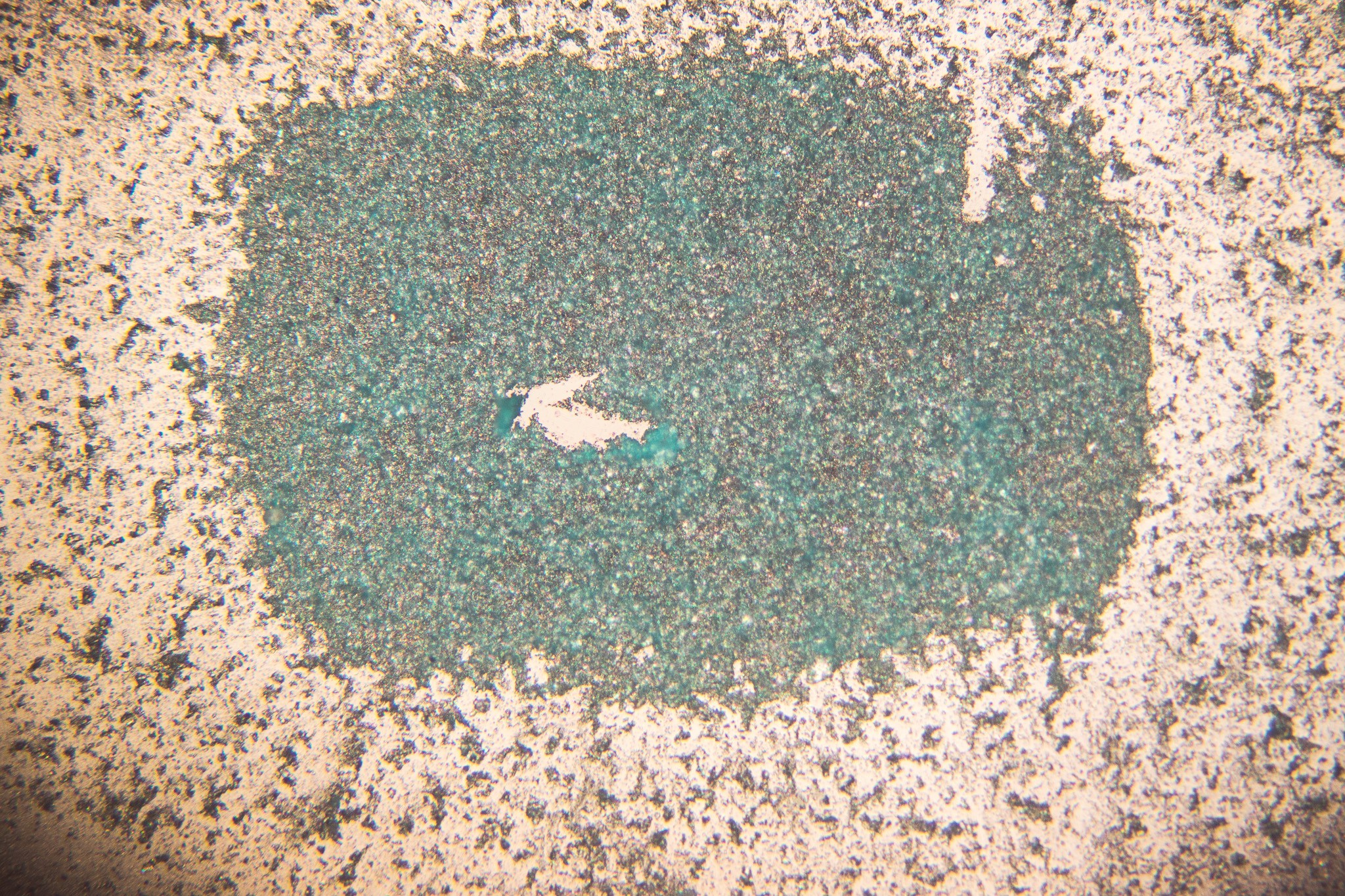
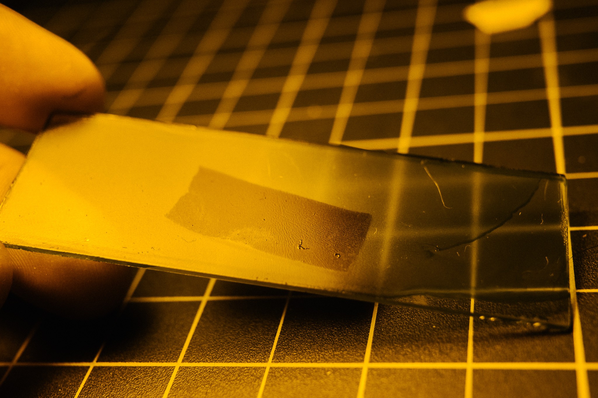
Remarkably, the projector worked too! After a gentle acetone rinse, there were two tiny little rectangles left on the slide. How good of resolution did I get on the test pattern? Well, here's one of the exposures under a microscope:
![]() So uh, yeah. Not so hot :)
So uh, yeah. Not so hot :)There are a number of things likely going on here. Firstly, the projector was probably not focused well. And the optic "bench" had tons of diffuse light spill from the projector, which would we trapped in the final build. So that probably helped expose sections that shouldn't have been exposed.
Then there's the acetone wash, which clearly does a bad job at developing. It doesn't cleanly remove everything, and seems to make the resist clump up. So that may have ruined any potential details.
Lastly, there's the resist itself. It's very possible the coating thickness was wrong. And I suspect I need to filter the resist after diluting with acetone. I did some reading and found mention that resists can suffer "solvent shock" if diluted with too much solvent, leading to large clumps that precipitate out.
On higher magnification, you can see how "grainy" the texture is. 20x magnification:
![]()
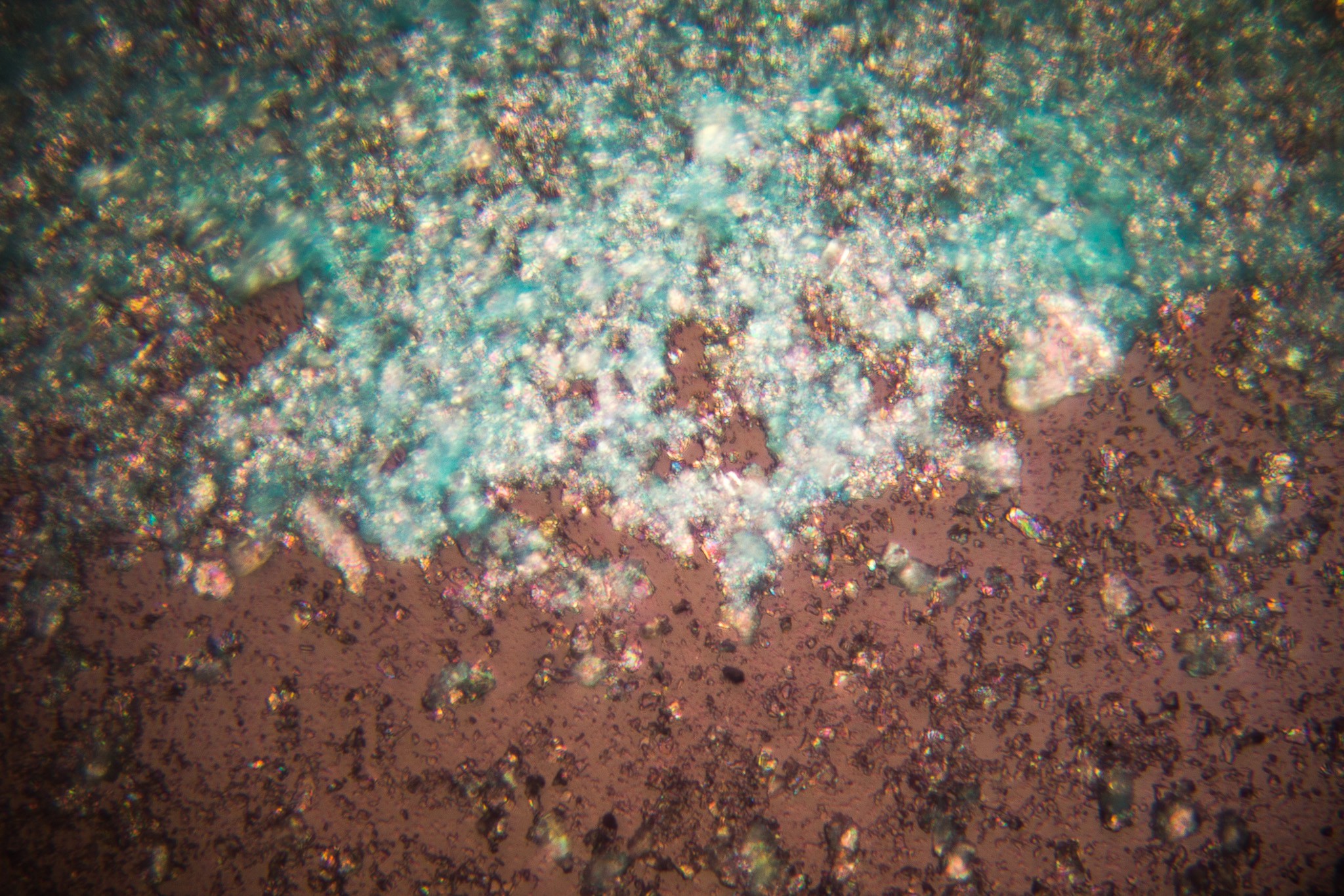
And 60x:
![]()
So that area definitely needs some work. I have some syringe filters on the way which should help. I also did some more research on semiconductor photoresist, and it seems like it is used at a fairly thick consistency. So perhaps I was diluting way too much, and the resist needs to be thicker. More things to fiddle with :)Anyhow, despite the abject failure of the test pattern , I'm over the moon that both the laser and the projector can expose the resist. Next steps is to set up a matrix of test parameters, determine a way to objectively rank the results and start testing the permutations. I'd also like to start working on replacing the LEDs with the laser. -
Photoresist spincoating tests
06/08/2017 at 18:09 • 0 comments![]()
Before any lithography can be done, I need to work out how to spincoat with photoresist. The photoresist I currently have is UV curable "solder mask" / "solder paint", which is used to mask off PCBs and resist solder adhesion everywhere except the pads.
The first few attempts were a bit dicey, but I think I figured it out by the end.
Spincoating is a two-stage process. The first stage the "coating" phase, which is a relatively low RPM spin. During this phase the photoresist is spread across the substrate. Interestingly, the final thickness is only dependent on the viscosity and the spin speed, not the amount of liquid that is added (assuming you add enough to coat completely). So the takeaway is that you shouldn't be stingy with resist, as the extra won't affect the final thickness.
As the resist is spreading, the friction of the liquid is fighting against the centrifugal force of the spinner. As the resist thins, the centrifugal force affects it less. The photoresist solvent also begins rapidly evaporating, which drastically increases the viscosity of the fluid, further slowing it down. Eventually, the resist stops flowing.
This all happens usually within the first second of spinning, which is why the initial parameters are crucial.
The second stage is the "drying" phase. During this time, the speed is ramped up higher and the main goal here is to simply accelerate the removal of solvent from the resist. The resist is likely solid before it hits this phase, so the thickness shouldn't change. Removing solvent helps make the photoresist easier to work with, retain better patterning, etc.
NOTE: in the video, I said the first stage should be 500-800rpm, and second stage 2000-3000rpm (which is what I did in the video). After re-reading some source material, I think the first stage is actually 2000-3000, and the second is something higher.
Ok, enough theory. :)
The solder mask was purchased on eBay (just search for "UV solder mask" or similar), and took a few weeks to ship from china. It comes in 100g pots, which should be enough to last approximately forever when being used for spincoating.
I started out with spinning just the plain solder paint. I knew it wouldn't work because it was too thick, but I wanted to establish a baseline. The results weren't pretty (well, they were aesthetically pretty... but not a good coating :) )
Apologies for the lighting in all these photos, I was working under a yellow lamp and my camera's white-balance went crazy.
![]()
From what I understand, solder mask is essentially acrylic resin suspended in some kind of organic solvent, mixed with a UV-sensitive photoinitiator. Luckily for me, that means you can thin it down with acetone (and perhaps other organic solvents).
So I glopped a bit of the solder paint into a cup and thinned with acetone, then tried again:
Better! I actually thinned it too much, which was immediately obvious because it started to evaporate/dry even before I began spinning. There wasn't enough mask particulate to cover evenly, and the acetone evaporated before it could cover everything.![]()
If I had added more fluid it may have worked, but looking under a microscope the "coated" portions still look pretty bare... there just wasn't enough paint in the mixture.
Third time's a charm, right? I let the mixture sit for a few minutes so the acetone would evaporate off, then tried again once the consistency was somewhere around milk. Opaque, but fluid and runny, slightly thicker than water (if I had to guess). That's inline with what the literature says photoresist should be. Quoting "Fundamental Principles of Optical Lithography":
Typical resist viscosities range from 5 to 35 cSt (1 Stoke = 1 cm2 /s). As a point of reference, water has a viscosity of about 1 cSt at room temperature.
And the results? Much better!
![]()
The coating is fairly uniform, covers the majority of the slide (excepting that bit on the right) and has a nice matte texture. If you look closely you can still see "spin" texture which may suggest it was a tad too thick, or perhaps some of the spinning parameters are slightly off.
As noted at the beginning, I was doing a 1000/3000 rpm schedule, when I should probably be doing something more like 2000/5000. Will need to keep playing.
Next step is to start developing these under laser and projector light, and figure out timing for that step.
-
Recreating an Achromat Microscope Objective
06/06/2017 at 13:13 • 0 commentsSo the idea of using a pico projector as a maskless lithography system seems sensible, except for one minor problem. Projectors making small images big, and we want the opposite. We need to convert the projector into a microscope-projector.
![]()
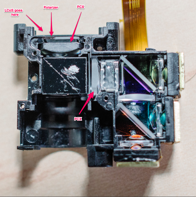
The first order of business is to remove the projection lens, which removes the vast majority of the image enlargement. If we revisit and annotate an image from the LCos Light Engine log entry, you can see that there are still a few hiccups to work around:
![]()
Because the illumination source is derived from a diverging light source (e.g. LEDs), the light cone needs to be focused onto the LCoS. This is accomplished with two Plano-Convex lenses, which act as condensers.
Unfortunately, if the light is being focused on the LCoS, that means it diverges when it exits the beam splitter. Of course, this is exactly what you want in a projector, but we need to find a way to shrink that image back down.
I debated pulling out one or both of the PCX lenses, but they are cemented in pretty well and I didn't want to scratch them, in case I had to put the lenses back in. So I got to work building an optical train to reduce the image.
De-magnifying the image
I have a 60x microscope objective that I was intending to use for this project. The idea was to focus the projector's light down to the right size/focal length so that the microscope objective could do the rest of the work.
This proved very difficult, unfortunately. My objective doesn't state it's tube length so I'm not sure exactly what kind of focal length is required to feed it. And collecting enough light from the projector has proven very difficult. You need either very short focal length lenses close to the LCoS, or much larger lenses farther out to catch all the light cone as it diverges.
Someone who knows optics would just sit down and do the math to figure out what's needed. That person is not me, unfortunately. So I just started fiddling with the various lenses at my disposal.
During the course of haphazardly fiddling, I realized that I had accidentally re-created a poor-man's achromat compound microscope objective. It focuses the light down to ~1mm rectangle.
I think I may just stick with this setup, rather than attempting to shoehorn a real objective in there (at least for the first prototype).
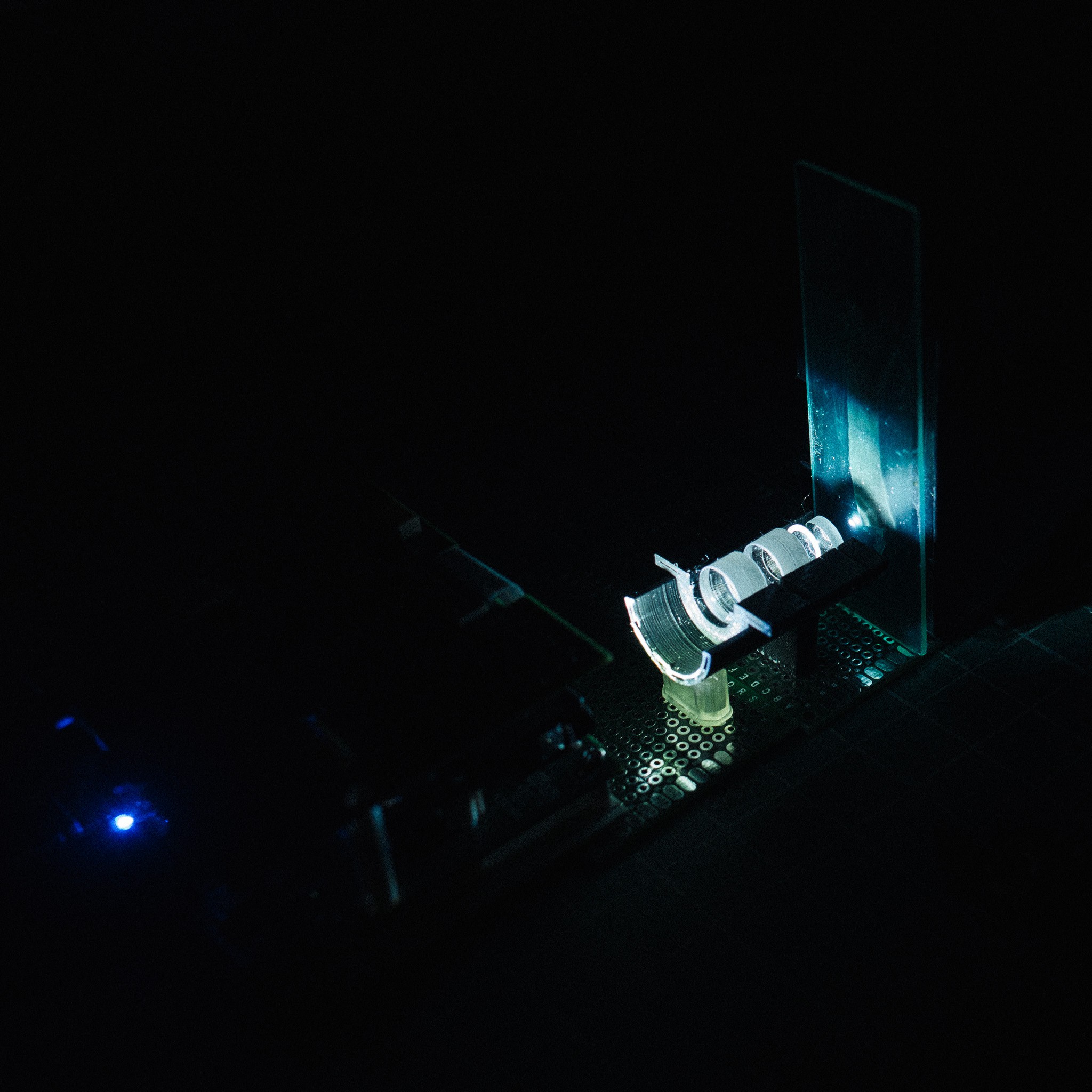
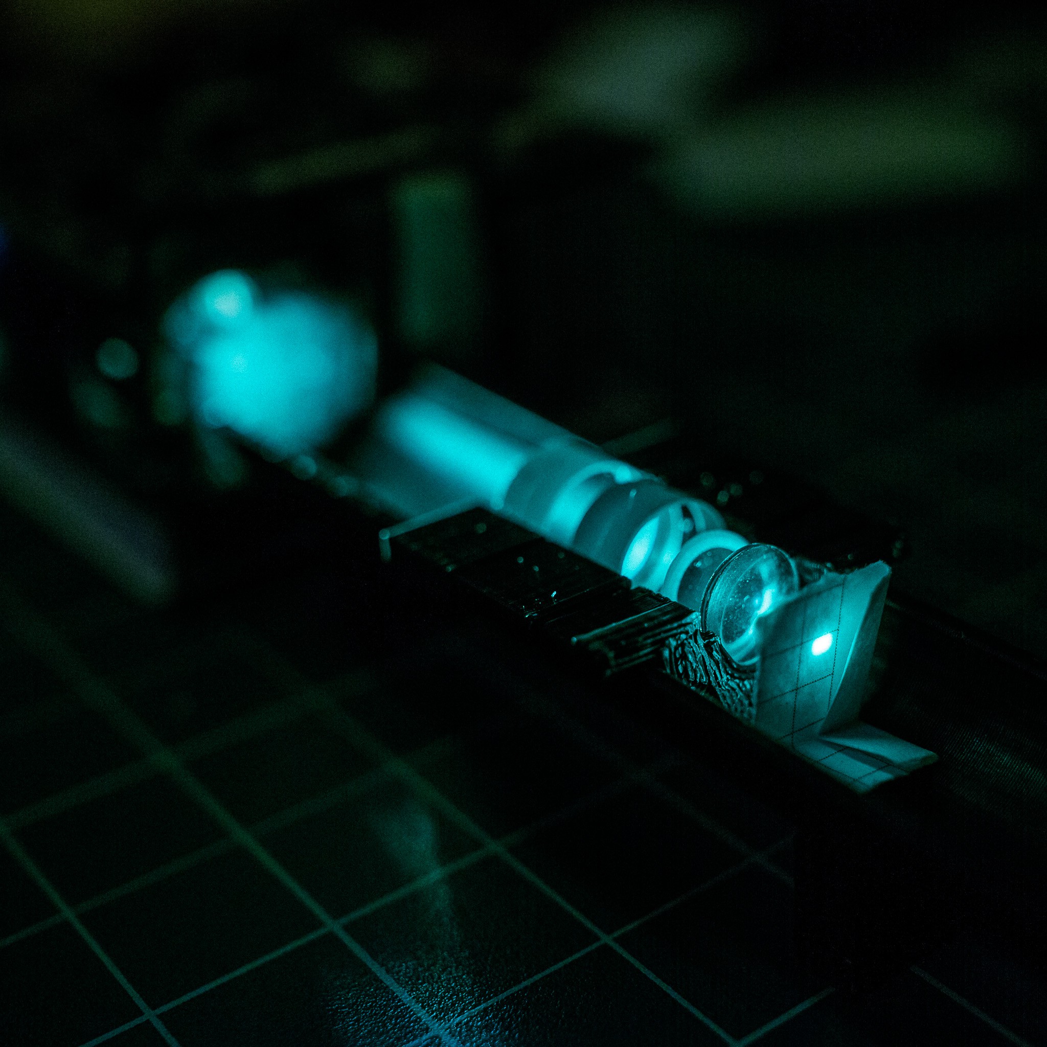
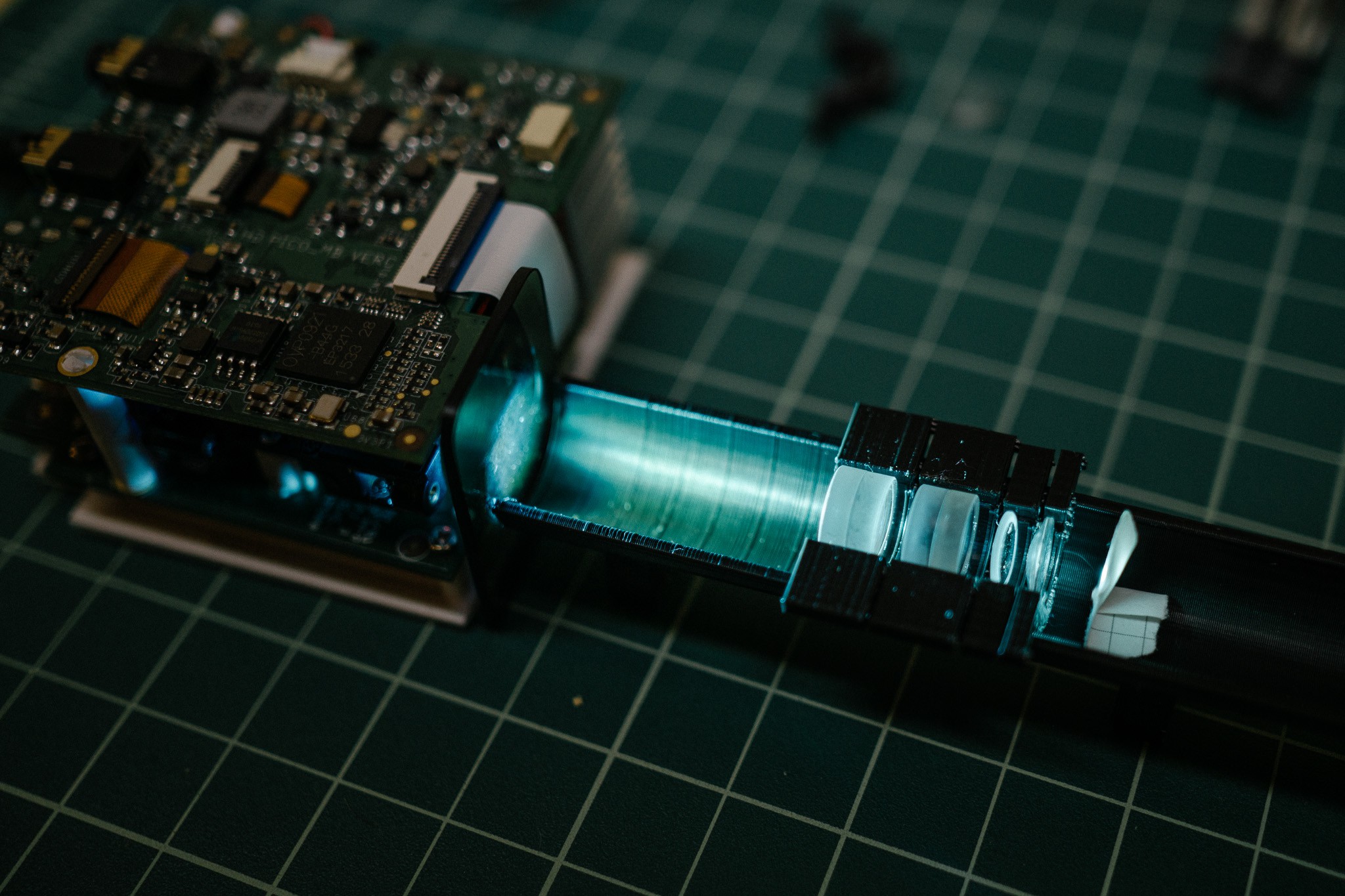
So what does it look like?
![]()
You can see the pico projector on the left. In front of the light path is a dark plate; that's a neutral density filter. The projector is not very bright relative to "real" projectors, shining a paltry 25 lumens. But 25 lumens focused to a single spot is still very bright to look at, and difficult to focus manually. The ND filter helps cut the output so it's more manageable to look at.
Then there's that black sushi-boat looking thing. What's that? It's an optical bench, but no, not the fancy optical bench I designed. As it turns out, I needed to position the lenses very closely together, and the bench I designed requires ~1cm between lenses due to the thickness of the holders. Oops.
So this is a simple print which is essentially a cylindrical boat. Lenses are placed inside little holders with varying sizes to accommodate different lens diameters.
Then there's the lens stack. It looks like:
- Achromat
- Achromat
- Positive Meniscus
- Plano-Convex
- Paper target
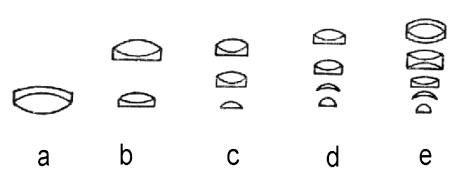
If you look at how achromat objectives are built (source):
![]()
You can see that it's very similar, albeit using a PCX instead of a hemispherical lens at the bottom.
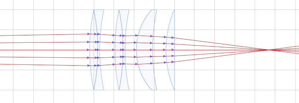
A quick raytrace looks something like this (with entirely made up lens parameters, these aren't the same as my actual lens... just for demonstration):
![]() I ran the numbers on the compound lens and think it is basically a 11x objective :D
I ran the numbers on the compound lens and think it is basically a 11x objective :D- 11x magnification
- 0.66 NA
- 3.9mm focal length
- Projected dimensions: ~0.85mm x 0.43mm
- Projector resolution: 1280x720
- Theoretical min feature size: ~0.67µm
*With the caveat that optics is entirely new to me, so I may have messed up the equations :)
405nm light is limited to ~606nm feature size anyway, so that's certainly good enough for me! In reality, I expect it to be several times greater than 0.67µm. There's vibration to deal with, I'm sure I have terrible spherical aberration from that PCX lens at the end of the stack, focusing is going to be difficult, process difficulties, etc.
Still, I'm rather happy how it turned out, given I know nothing about optics. :)
The next step is to incorporate a beam splitter somewhere so I can use a camera to help position, and to figure out how best to replace the LEDs with a laser (or maybe just bigger LEDs).
Fun aside
Amusingly, when trying to take photos of the setup I noticed this weird chromatic effect in my camera:
It was noticeable in the live preview, and even more in the video. What's going on? Have I created some fantastical machine which slows down light so much you can see it shift colors?
Nah :)
Cheap (and small) LCoS projectors like mine use a single LCoS chip, unlike more expensive ones which have a chip-per-color. That means the colors are actually being shown sequentially; turn on the first LED, display the pattern on the LCoS for that color, switching to the next LED, etc etc.
Apparently, the frame-rate on my camera was juuust righ to catch this in action, and create the effect of slow-moving chromatic changes. It's similar to the optical illusion of seeing wheels "spin backwards" when they are rotating fast enough.
Pretty fun to watch though :)
-
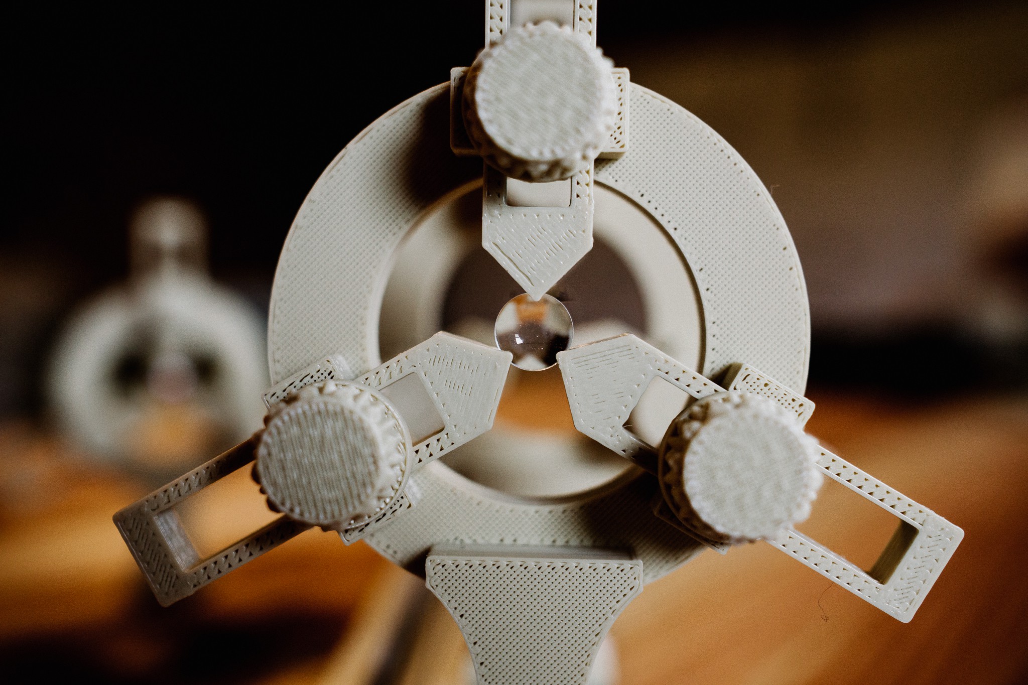
3D Printed Optics Bench
06/05/2017 at 01:29 • 0 commentsIf you've ever played with lenses, you'll quickly recognize the need for some kind of optics bench. An Optics Bench is really just a fancy name for some kind of system to hold lenses precisely in line with each other, at adjustable distances.
With a bench, you can easily setup multiple lenses, splitters, mirrors, etc to play around with compound systems.
Optic benches are crazy expensive unfortunately. This is partially because they are precision devices meant to be used in experiments, and partly because they are relatively niche (experimenters, and students).
There are numerous ways to create simple optic benches, but I opted for the 3D printed approach.
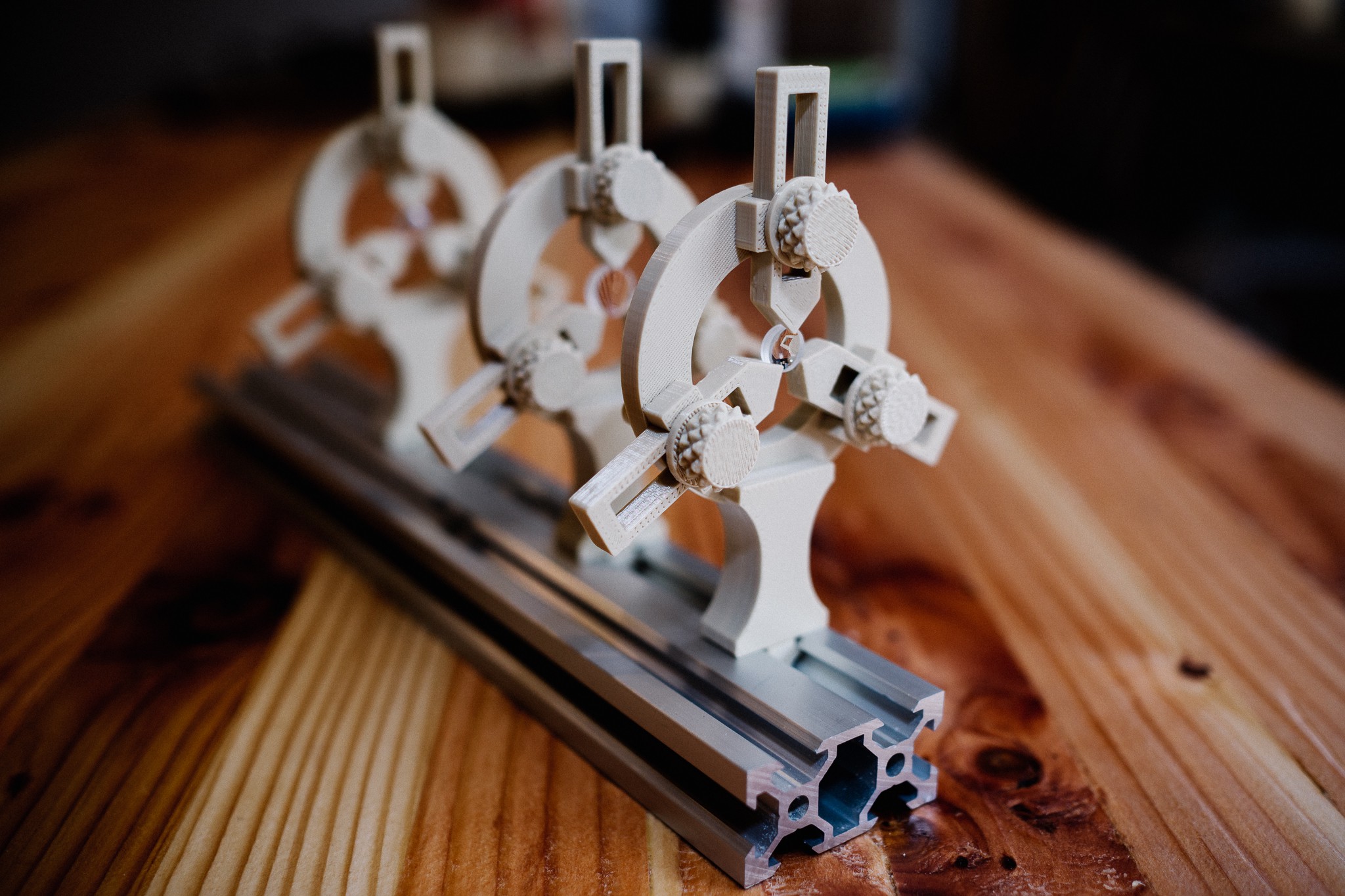
![]()
My lens holders are available on Thingiverse if you want to print some yourself. They are semi-parametric, in that you can adjust the maximum lens size they can hold, and the height at which lenses are held.
Lenses are held in place by three clamping sliders, which have a little V-cut at the end to hold onto the lens. The sliders are held in place by pressure from a washer and nut (also printed). Aluminum extrusion is used as the rail to align the holders, and each holder is attached with a moveable t-nut.
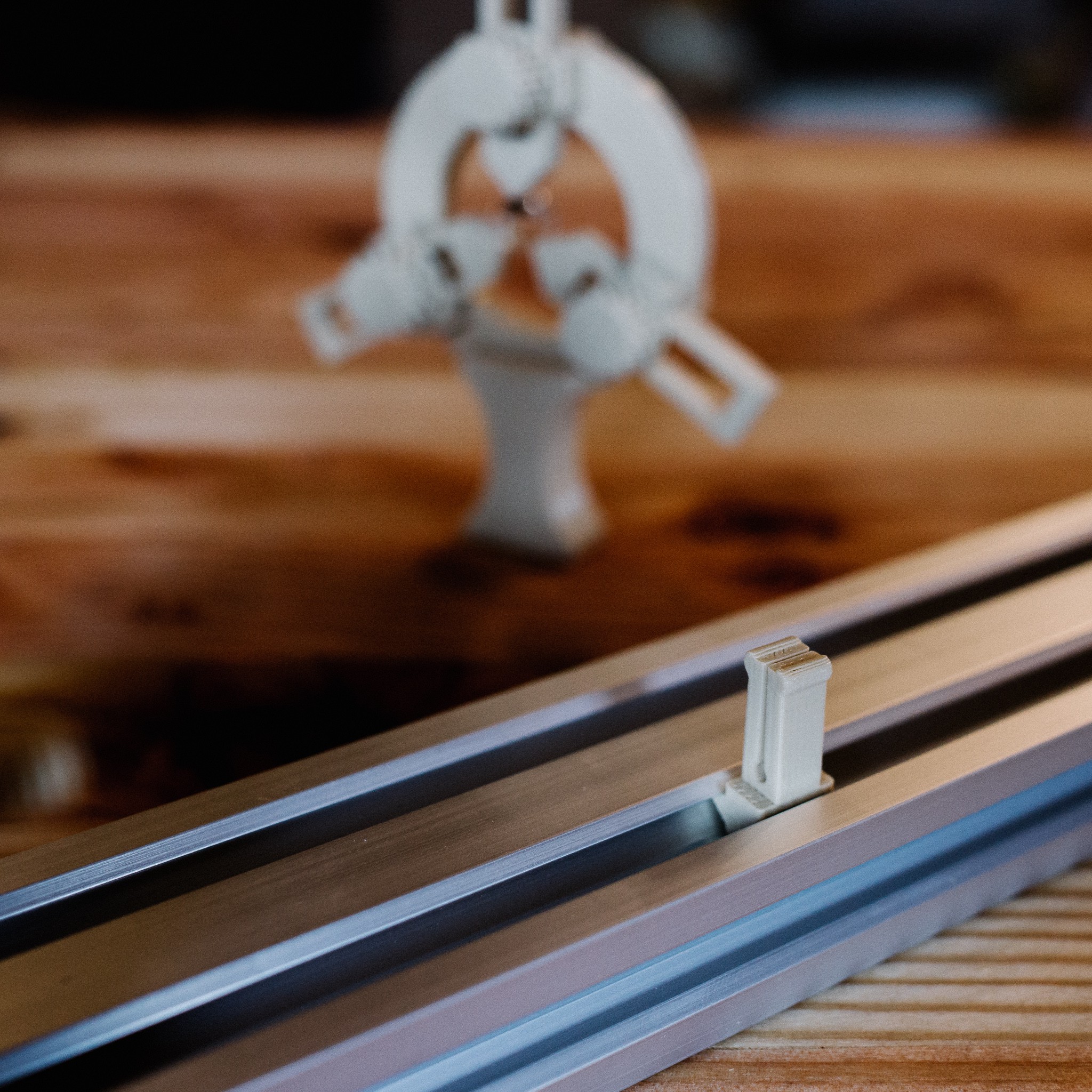
![]()
Many DIY benches are limited to one dimension, because they are built with simple things like wooden dowel rods. By using aluminum extrusion, you can easily setup perpendicular light paths using standard 90 degree connectors.
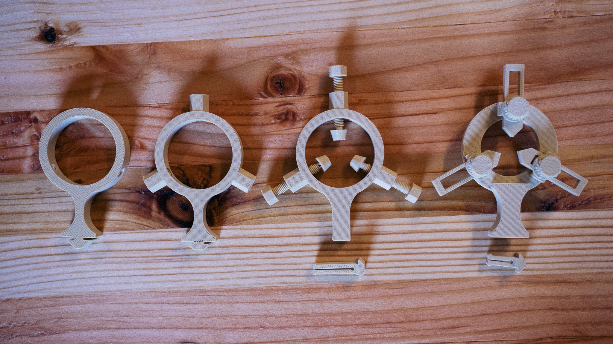
I was hoping to knock these parts out quickly, since I wanted to start prototypic objectives. Much to my chagrin, it took a number of iterations to find something usable.
I originally tried a simple ring with threads for bolts. The idea was that the bolts would press agains the lens and hold it in place. That failed miserably... it was simply too hard to snug the lens with a rotating bolt and keep everything registered/level.![]()
The next iteration added a ball-joint to the end of the bolt. Small clamp-heads were then clipped onto the ball joint. Each head had a v-slot cut out of it to hold the lens. This worked better, but was still very fiddly.
After looking at how some commercial units were designed, i ended up at the current model. Sliders that are held in place with friction from a washer/bolt. It can be a little tricky to center, since the sliders are not as easy to fine-tune as the bolts, but overall it's a much more usable system.
![]()
-
LCoS Light Engine
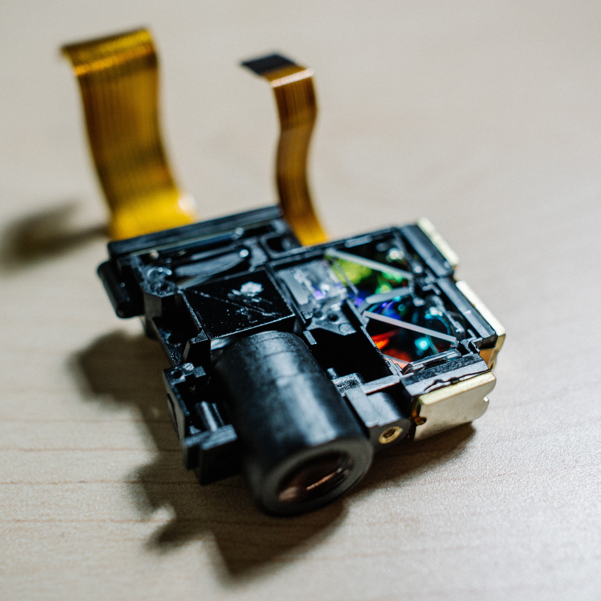
06/05/2017 at 01:09 • 1 commentHaving received my pico projector, the first order of business was cracking it open to take a look at the light engine.
![]()
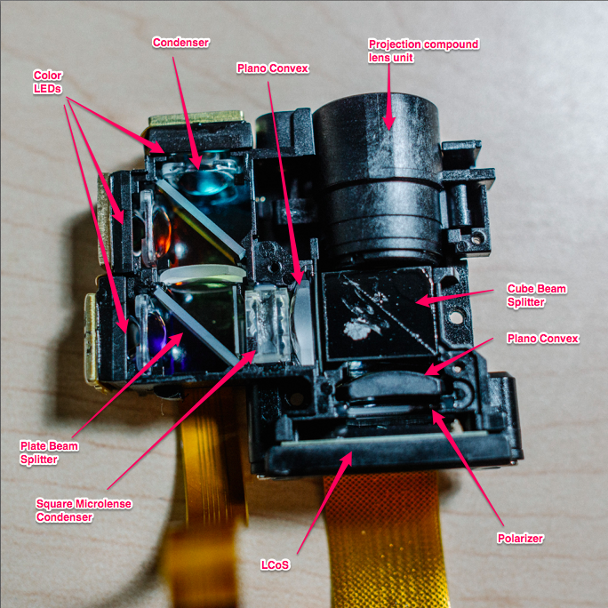
The light engine is a pretty compact little unit, measuring only a few centimeters wide and one cm thick. After poking around a bit, I believe I've identified all the important bits. Here is an annotated view:![]() As you can see, there are three LEDs which provide the illumination. These LEDs are coupled to small heatsinks, which are then attached to a much larger heatsink (not pictured) via thermal tape.
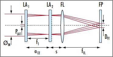
As you can see, there are three LEDs which provide the illumination. These LEDs are coupled to small heatsinks, which are then attached to a much larger heatsink (not pictured) via thermal tape.Each LED sits behind a plastic condenser lens, and are then folded through 1-2 beamsplitters. The light is projected through a square microlens array. I wasn't familiar with what these arrays do, but Edmunds provides a good summary:
Microlens arrays are useful for homogenizing a variety of modern light emitters from line-narrowed excimer lasers to high power LEDs. Microlenses are well suited for applications that require high efficiency and non-gaussian uniformity.
Square microlenses are commonly used for beam homogenization and shaping, yielding spot patterns or a square flat-top pattern. The lenses feature a high fill factor which eliminates zero-order hot spots in the illuminated field. Square lenses are often used in pairs, in conjunction with a PCX lens (see above)Beam homogenization setups typically consist of a pair of square microlens array and a plano-convex (PCX) lens. The homogenization plane FP is located at one focal length distance ƒFL behind the spherical lens FL. The first array LA1 divides the incident beam into multiple beamlets. The second array LA2, in combination with the spherical lens FL, acts as an array of objective lenses that superimpose the images of each of the beamlets onto the homogenization plane FP.
![]()
So there you go, it seems the array is being used as a kind of diffusor, to even out the hotspots from the LED. It is immediately followed by a plano-convex lens just like Edmunds noted. The LED light is then sent into a cube beamsplitter, which redirects the light towards another PCX lens. This lens focuses it through a polarizer (I think) and then impacts the LCoS chip.
Light is then either absorbed by off pixels, or reflected back through the beamsplitter, through the project lens and out into the world for viewing.
All in all, a pretty cute little package. The projection lens is a group of several plastic lenses, which all work to enlarge the image without introducing too many aberrations. It's focused by sliding forward/backwards with a thumbscrew.
![]()
I didn't try too hard to identify the lenses to be honest, since I want to make the projected light small, not large. They are likely different combinations of negative mensiscus and PCX / PCV lenses. They were spaced in the housing with plastic washers.![]()
Another view of the light engine, without the projection lens:
![]()
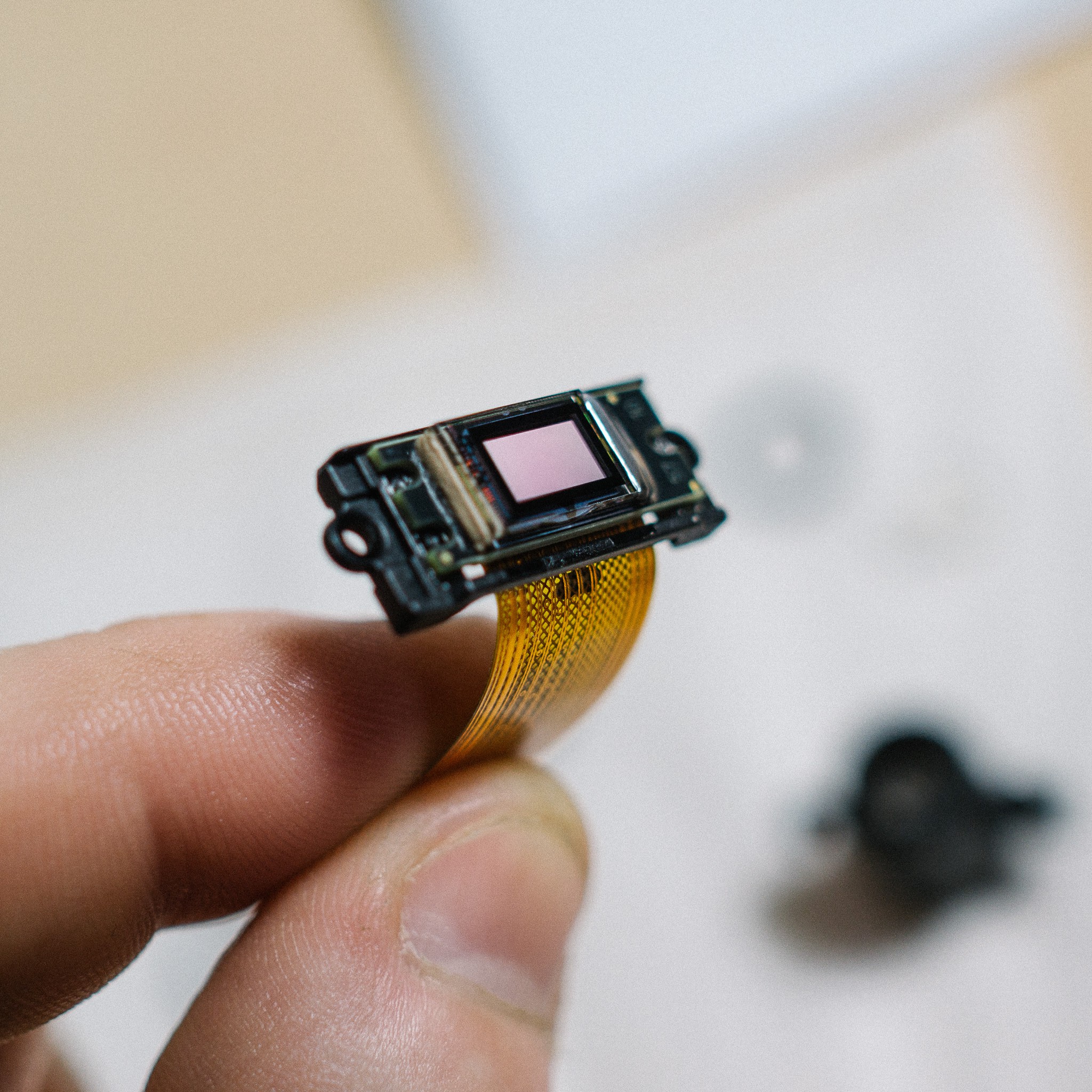
And finally, the LCoS itself. It's a tiny little chip, with the active area measuring perhaps 10x5mm. It attaches to the light engine with two screws, and includes a small PCB with some minimal support circuitry.
![]()
-
Spincoater from old HDD
06/05/2017 at 00:23 • 0 comments![]()
While waiting for components to arrive, I set to work on building a spincoater. Spincoaters are used to spread photoresist evenly on a silicon wafer (or anything else you need to coat, such as glass slides).
They can be purchased on eBay for a reasonable sum. Proper spincoaters give precise speed, automated ramp up/down profiles, exact timing and vacuum chucks to hold the wafer.
But for my purposes, simple DIY will probably be ok to start. There are tons of DIY plans on the internet, ranging from simply taping your wafer to the back of a fan, to using an old hard drive, to a full microcontroller project (from the ever-excellent Ben Krasnow)
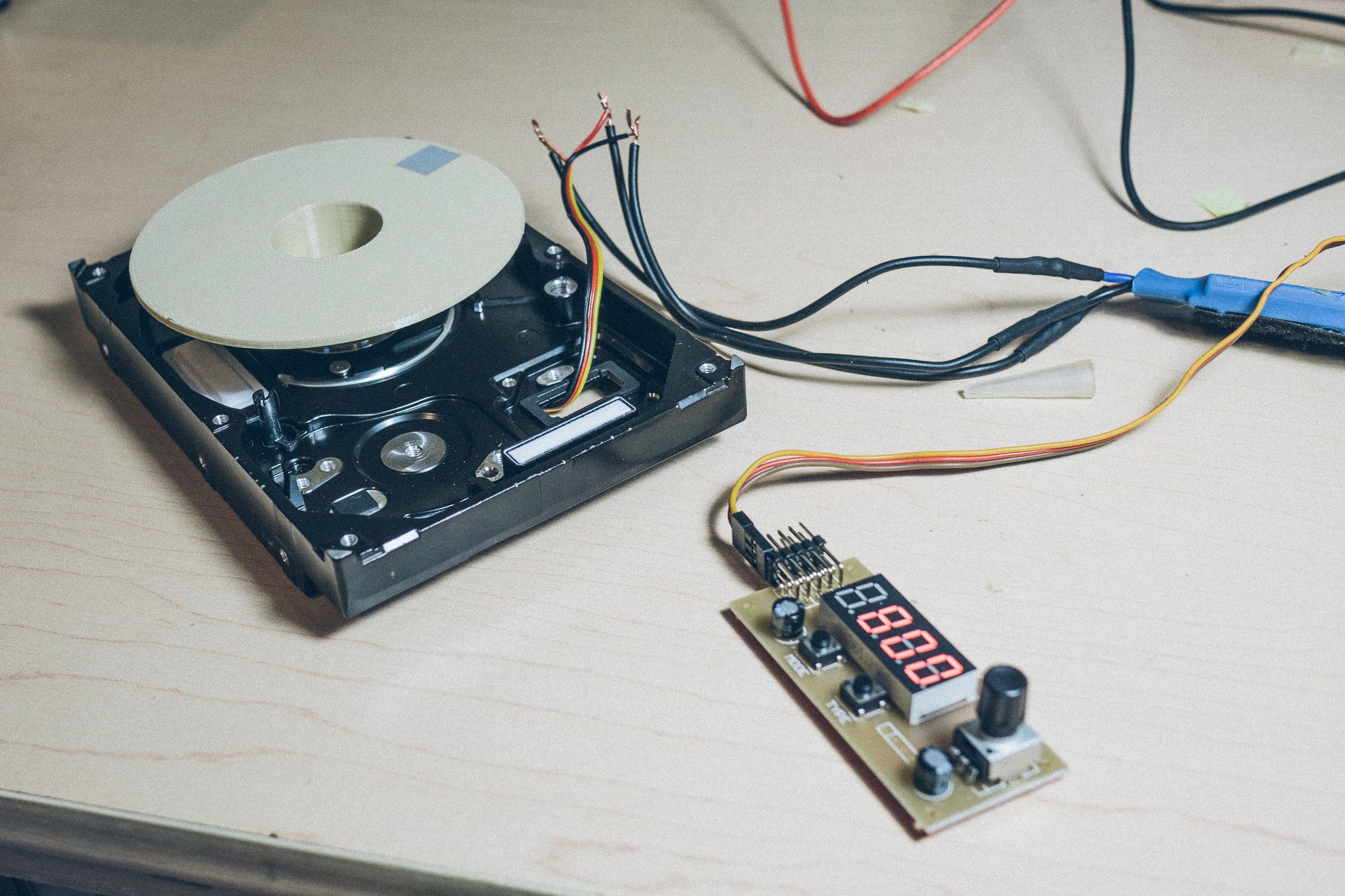
I opted for the HDD route since I have several laying around (I mean, who doesn't?).
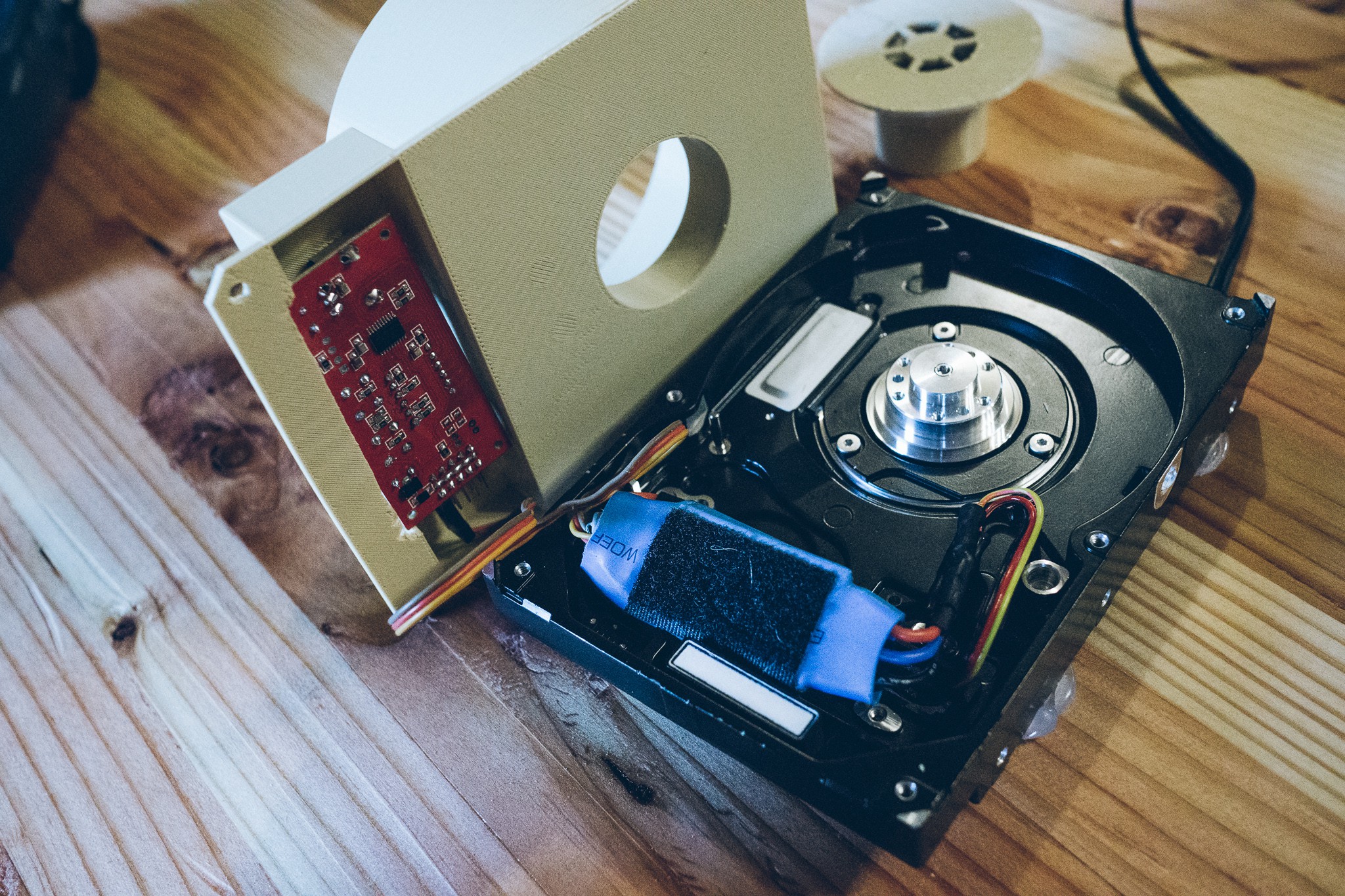
HDD’s have brushless motors just like those used in quadcopters and FPV drones, which means you can use a cheap hobby ESC to drive the motor. The motor itself is tiny and has a max current draw of 400mA, meaning a really lightweight ESC is fine. I used one that I had laying around the house.
RPM of the motor can be controlled via the PWM output of a servo tester. The servo tester I grabbed off Amazon has a few extra features, such as adjusting the pulse-width timing and a digital display of duty cycle. But a cheaper tester without a digital display would work fine too.
The motor takes 12V, so I rummaged in my spare parts drawer and found a small 12V 1A wall-wart which did the trick nicely. We just moved and I can't find any of my barrel connectors, so I just sacrificed the wall-wart and permanently soldered it on.
![]()
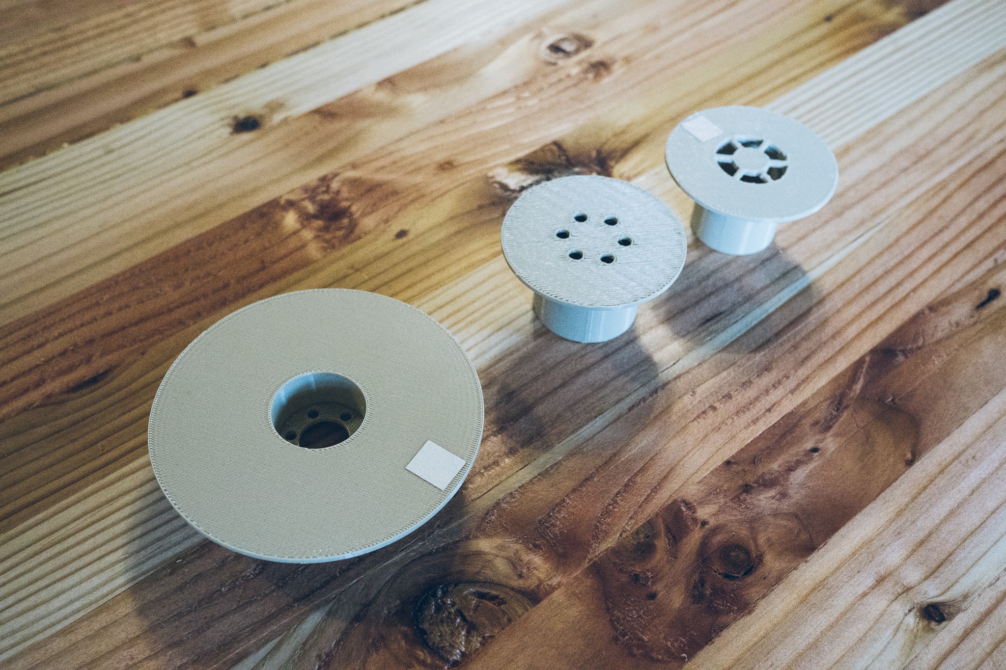
I printed a simple chuck to go on top of the motor, and mounted it with the same screws that held down the original platters. Voila, the basis of a spincoater! You can see it in action here, attempting to vibrate off the table:
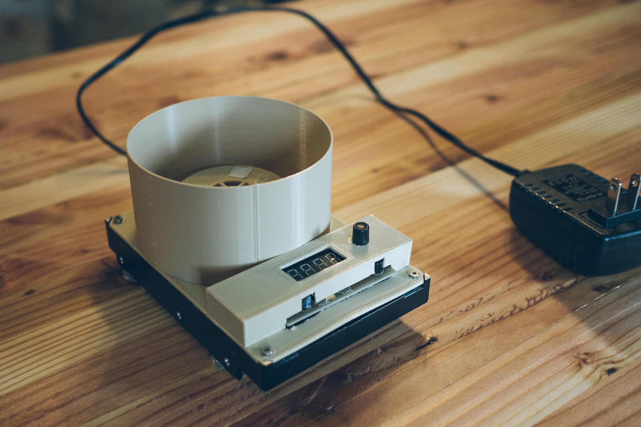
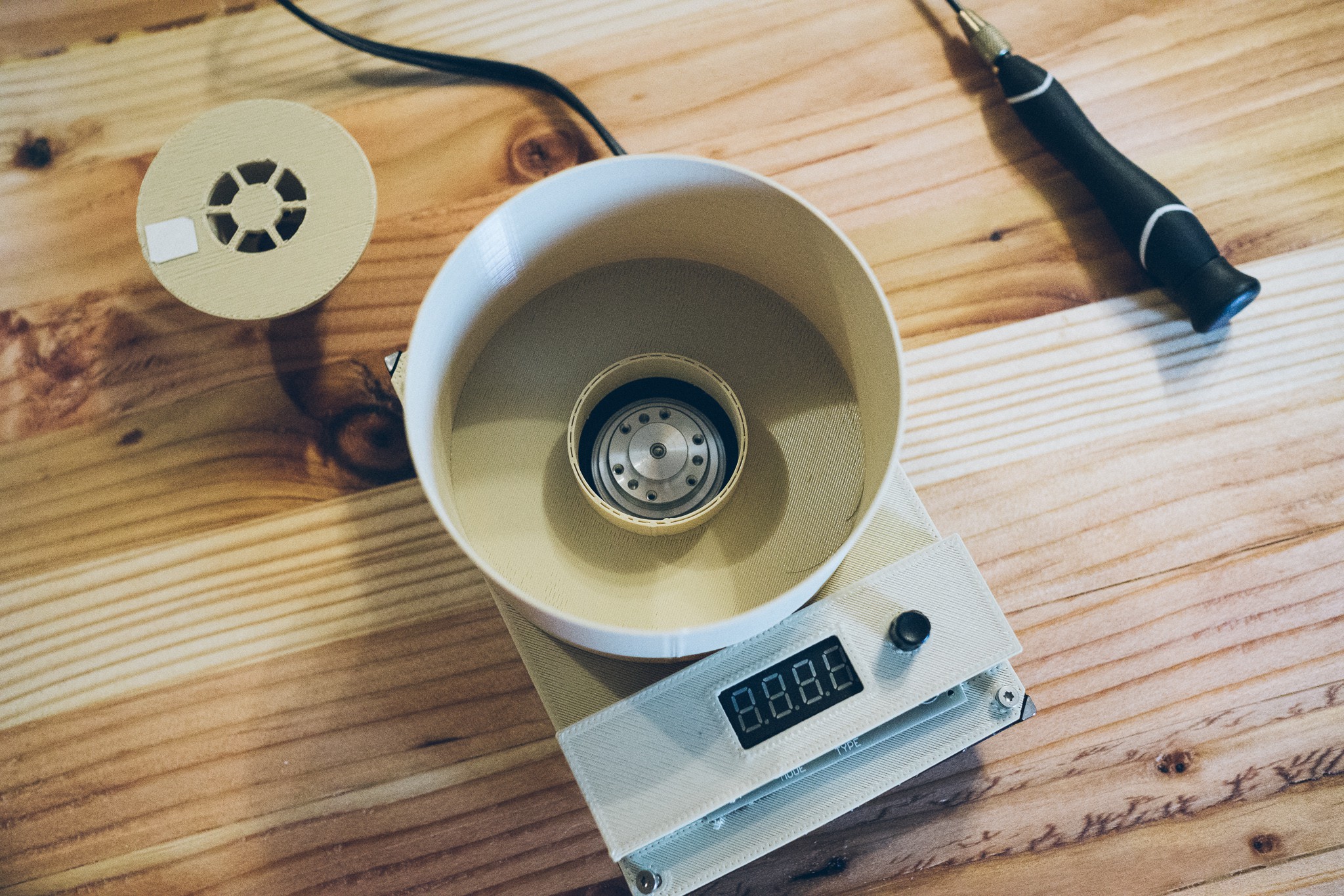
After that it was just a simple matter of printing up an enclosure to hold the electronics, and create a splash guard around the wafer chuck.
![]()
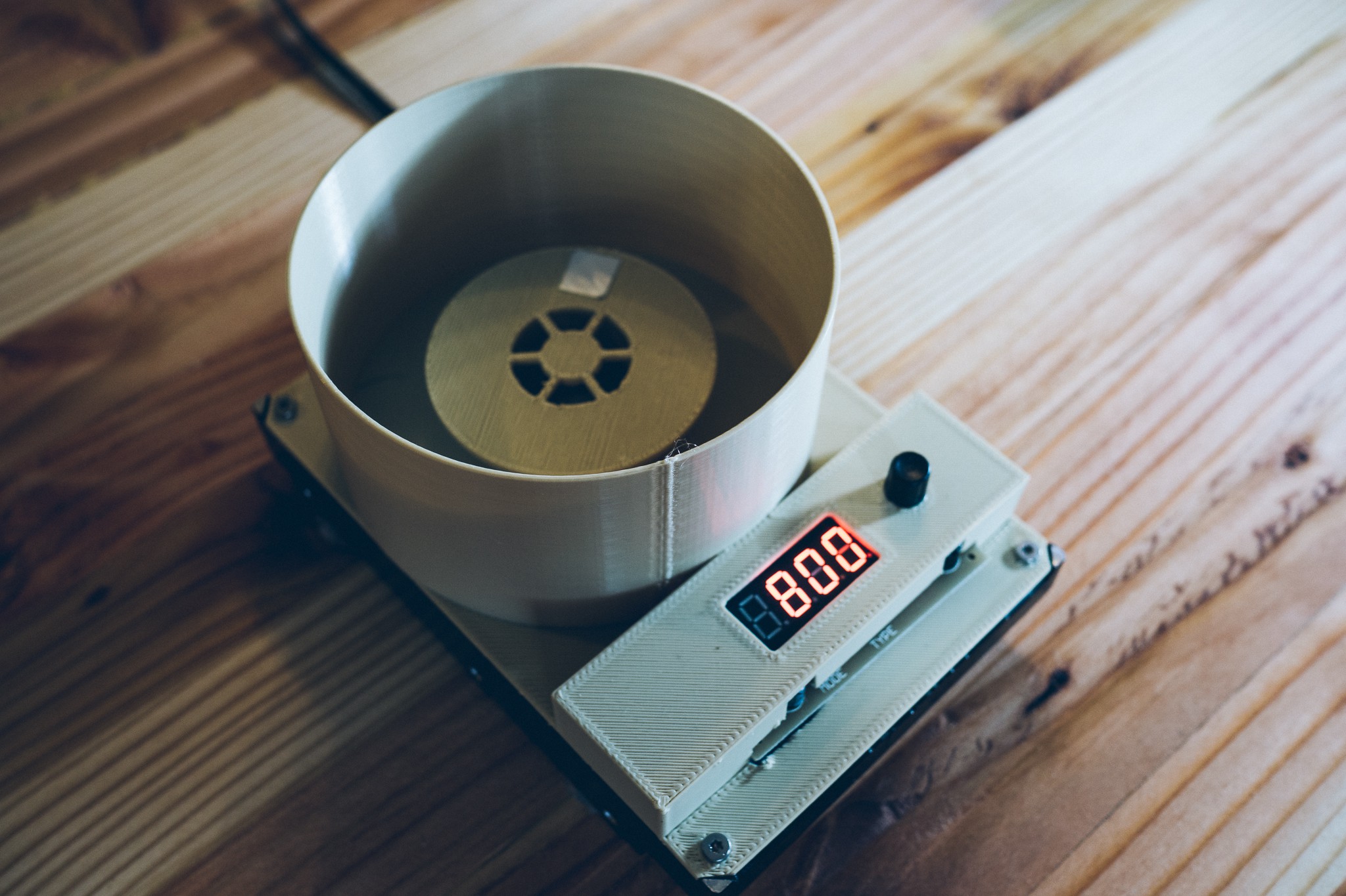
I printed several chuck designs but settled on one that is mostly hollow and relatively small. Larger chucks were more difficult for the lightweight HDD motor to get up to speed quickly, and had more momentum to slow down.
![]()
The chuck has holes aligned with the old HDD platter mounting system, so it can simply be screwed onto the drive shaft. In reality, the friction fit alone would probably suffice but I’m a bit too paranoid :)![]()
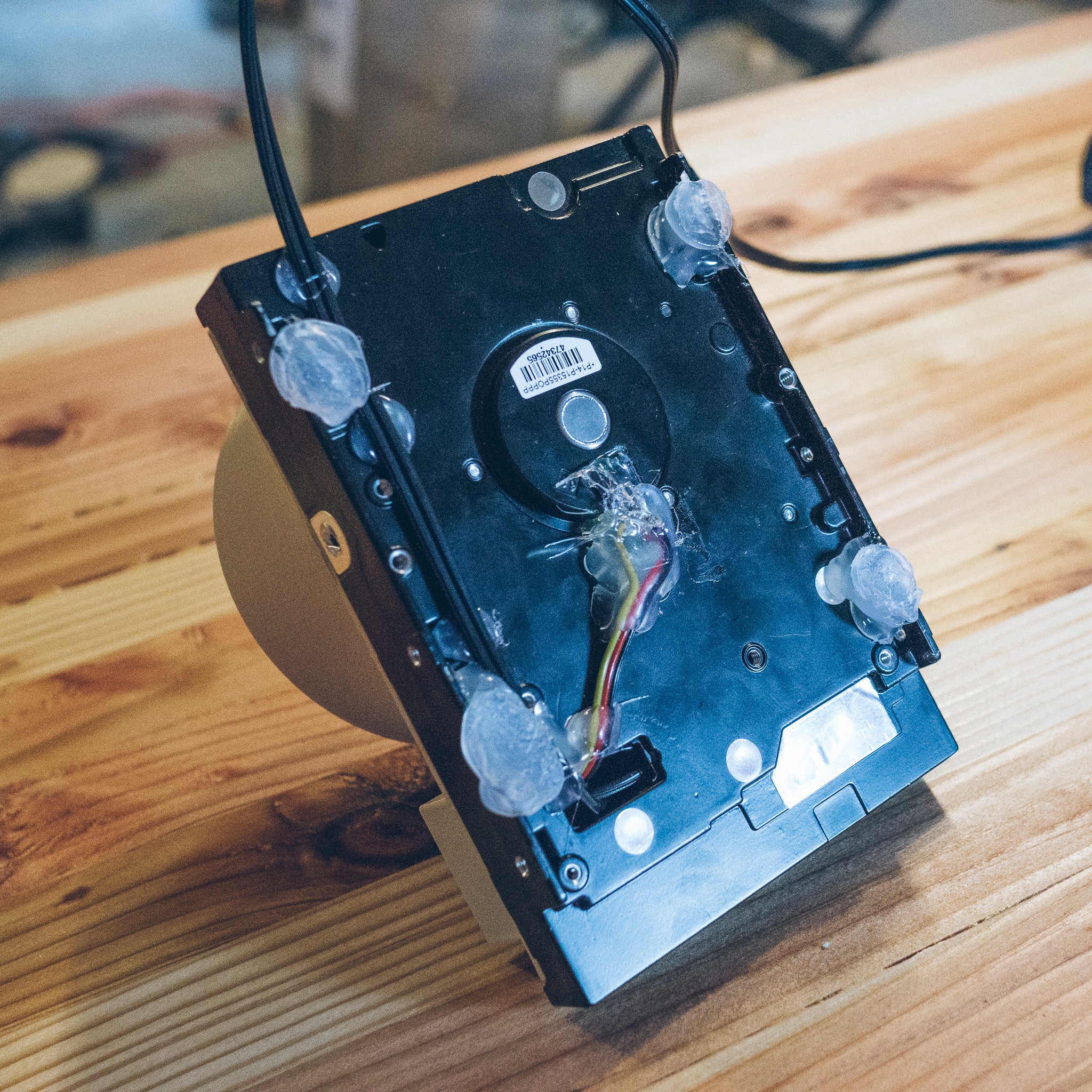
The bottom is a disgusting mess of hot snot. The soldered motor leads were encased in hot glue to help support them mechanically, and then some ad hoc feet were created with large blobs. That does a surprisingly good job of stabilizing the spincoater.
![]()
The electronics are just crammed inside the enclosure, nothing special in the mounting. The enclosure was essentially printed to the size of the components. Alas, I’m bad at 3D printing and measured incorrectly, so I had to cut away some of the enclosure because the edge of the board and two capacitors were too large.
![]()
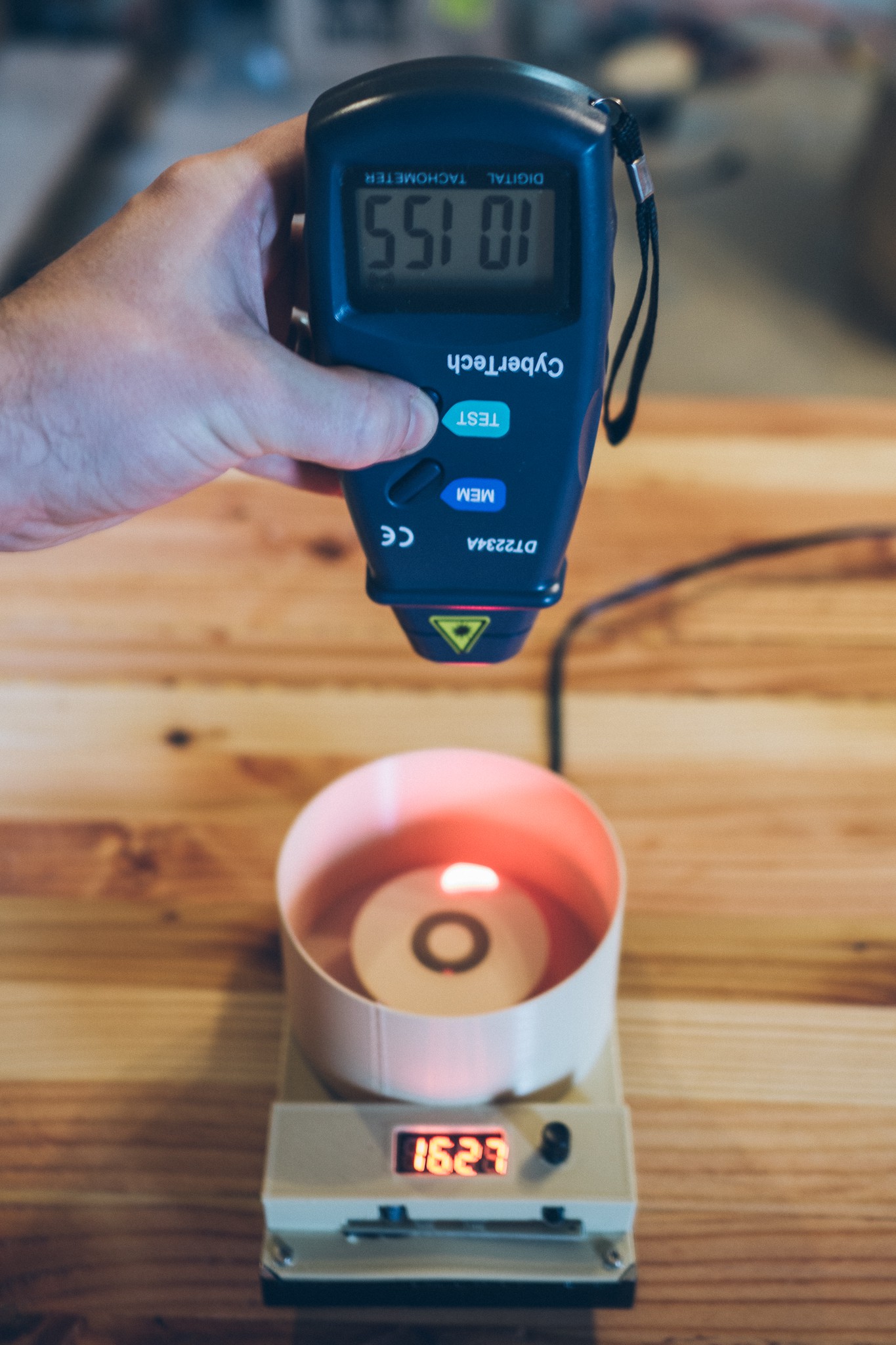
The spincoater can get up to around 10-11k RPM, based on a cheapo laser tachometer that I have. I only need speeds up to ~3000 RPM, so that will do just fine. I chose the servo tester with a digital display so that I can find the exact duty that gives me the RPM I need.
![]()
And the final product in action:
Future Changes
If I ever get motivated, I’ll reprint the enclosure to properly fit the electronics. More importantly, I’d like to print some kind of lid which can be used during operation. Or perhaps cut some clear acrylic so that I can see what’s going on.
I’ll also likely print a large knob for the servo controller… the current knob is very fiddly to position accurately.
And finally, I’ll probably print some custom wafer chucks once I actually buy some wafers. My plan is to start with simply double-sided tape, but eventually I’d like the chuck to have some sort of lockdown mechanism. Unfortunately I doubt any of this janky setup would work with a vacuum system, so I’ll just have to stick to hold-downs.


 So uh, yeah. Not so hot :)
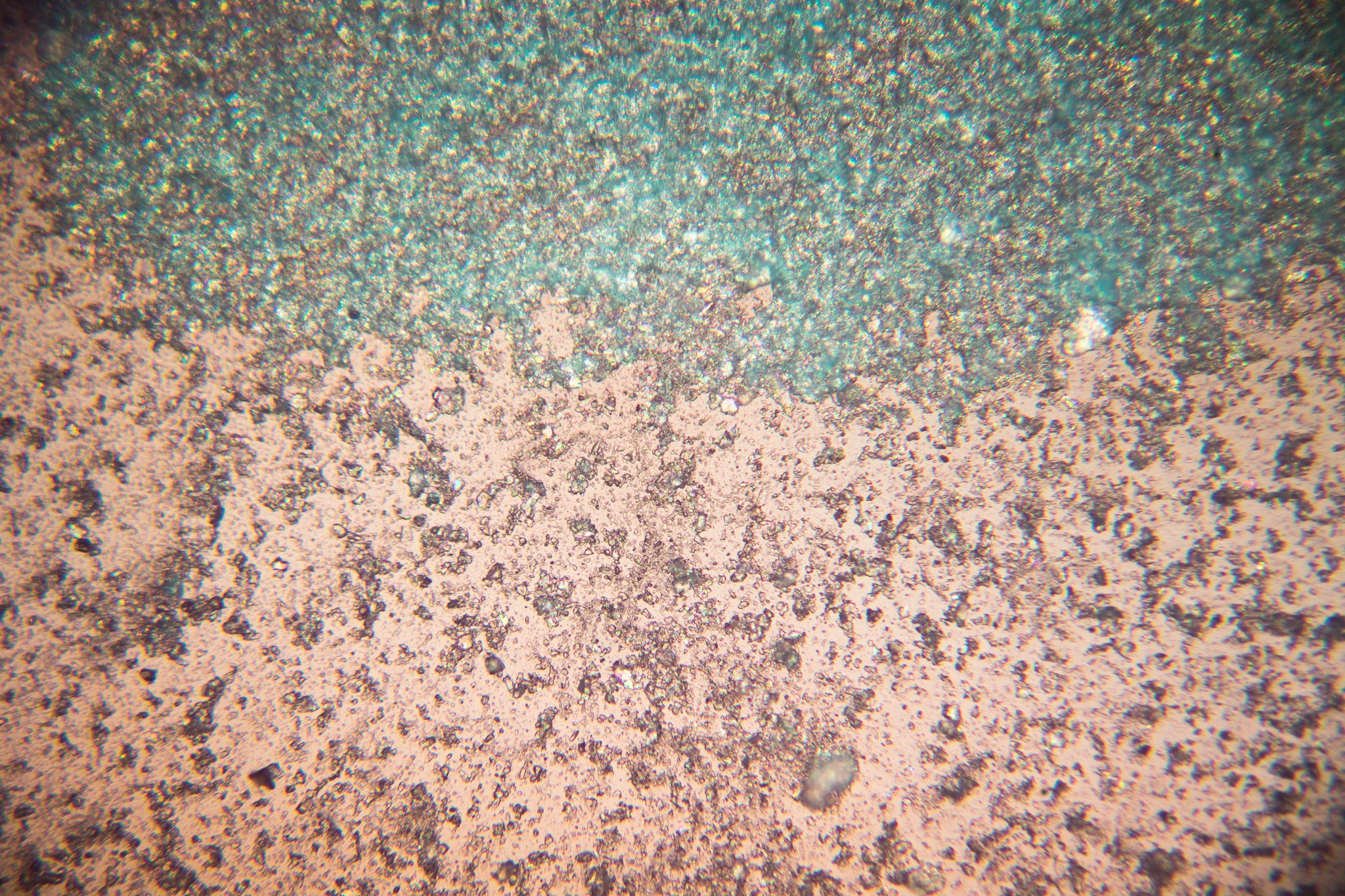
 As you can see, there are three LEDs which provide the illumination. These LEDs are coupled to small heatsinks, which are then attached to a much larger heatsink (not pictured) via thermal tape.