-
Delay
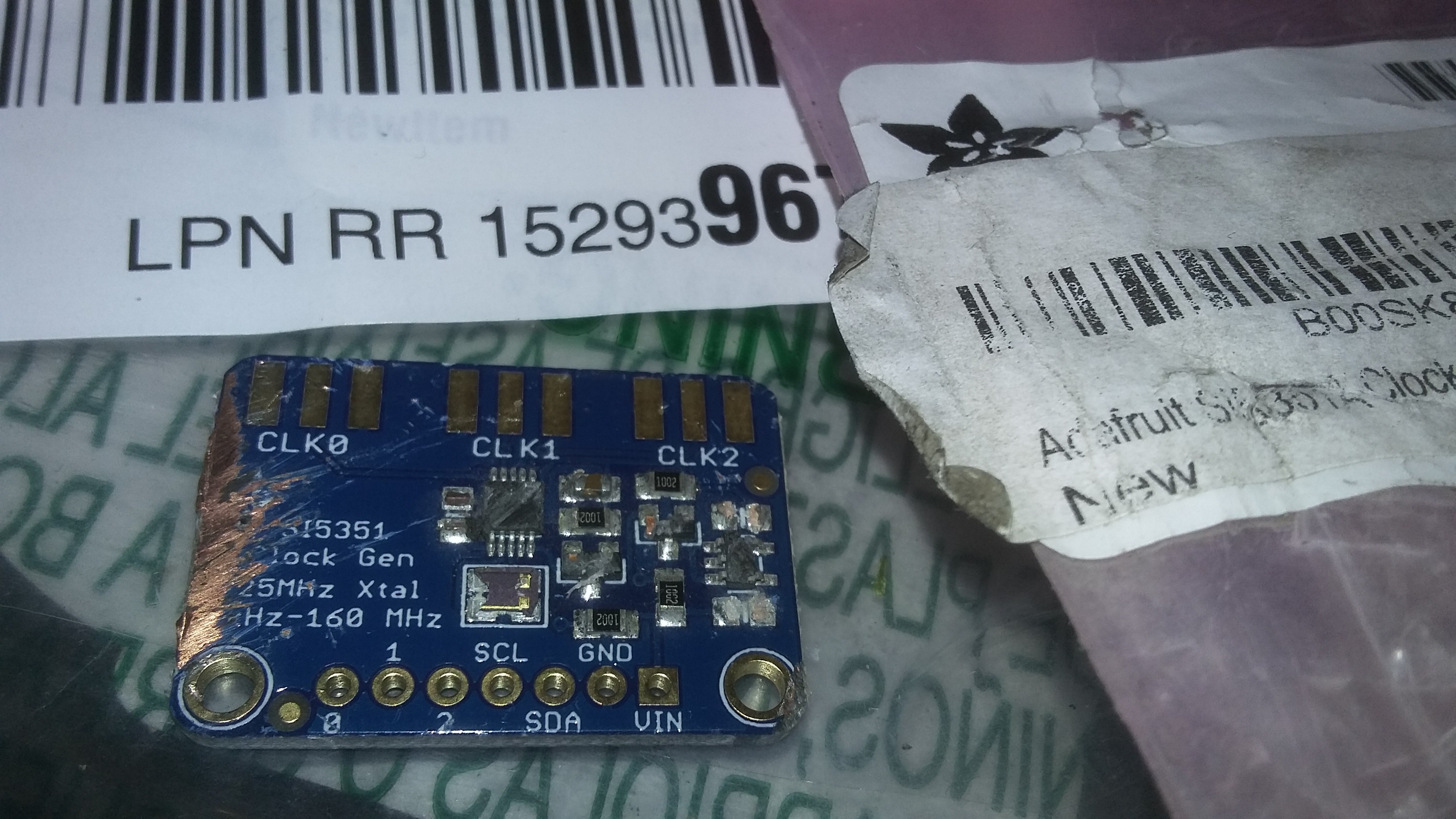
06/12/2017 at 19:01 • 0 commentsPardon the lack of update. I intended to have a working VCO and LO by now. I decided to switch to the SI5351 since it is both cheaper and much more functional than the AD9850. The SI5351 can generate 3 or 8 clocks depending on the physical package size you select. I am going to try to do everything with 3 clocks. This should be easy. This also means that the LO and VCO are both frequency agile. The LO is normally fixed at 10.240 MHz. Shifting that around slightly along with the VCO might be interesting to experiment with. Also, IF Shift may be possible to implement in software this way.
As such, I ordered a SI5351 from Amazon to save shipping cost. The package arrived mislabelled. There was an Amazon inventory sticker over the Adafruit sticker. Amazon sticker indicated it was a 2045 but the Adafruit one showed it was really a lithium battery charger. In hindsight, I probably should have kept it and used it for memory backup. But I did the honorable thing and returned it.
And ordered a new one. Which arrived on Sunday. Absolutely demolished. Looks like it was caught under a belt. The killer is that the destroyed part was inside of a sealed Amazon inspection bag. So Amazon picked up a few of the bits of the shredded board, stuffed them in a bag, printed a new envelope and just called it good? Weird. So, fool me twice, I ordered another from Amazon. Dernit. Because shipping from anywhere else costs a mint compared to the cost of this board. Which is good for us because it means the board is cheap. ;)![]()
-
Front Panel and Synth Prototype
06/09/2017 at 19:50 • 0 commentsUnfortunately, Amazon shipped me the wrong breakout board from Adafruit. Not an uncommon occurrence these days. That said, I will likely spend some time to probe and record signals on each of the connectors coming into PB121. Just to make sure I understand them all and what their ranges are. For example, I need to ensure that all voltages are under about 5.5-6.0 V to avoid damaging anything. Some of the signals to/from PB121 are 8 V as is common in VCO circuits. And then verify that certain signals are control voltages versus digital logic.
I will be first wiring up the front panel connections. Everything that isn't the PLL.
-
PB121 Block Diagram v1
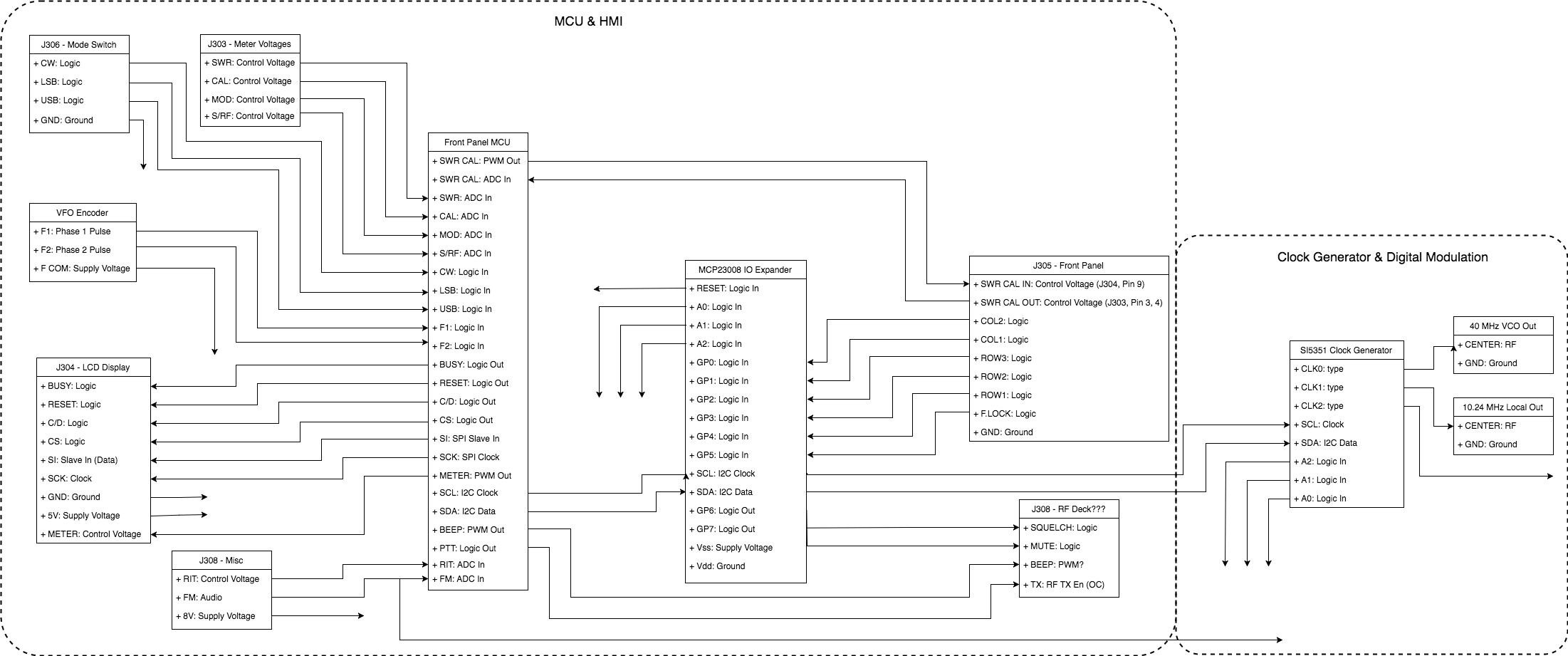
06/09/2017 at 09:25 • 0 commentsMapping out the needed signals for a replacement PB121 board. This should be a complete diagram of the proposed interconnections. I have shared this Block Diagram via Google Drive using Draw.io.
![]()
-
Alternative HR2510 Display
06/08/2017 at 00:41 • 0 commentsThis is a video from years ago showing a concept for a two line character display and AVR micro to replace the missing PB112 board. This code will likely be adapted into a library that is also compatible with the HR2510 PB112 interface. With a means to capture the display data we can make this happen easily. In fact, it would already be done if I wasn't having an issue with the display. The HR2510 has a very small space to fit the full LCD and it took a long time to locate a LCD that would fit. However, this display has stopped working after some manhandling over the years and they are, predictably, obsolete.
-
HR2510 PB112 LCD Display Library
06/08/2017 at 00:33 • 0 commentsA rather boring video of me rambling while spinning the VFO dial and seeing data for the first time.
The code driving the display can be found here:
https://github.com/hamspot/hr2510/tree/master/libraries/HR2510_PB112
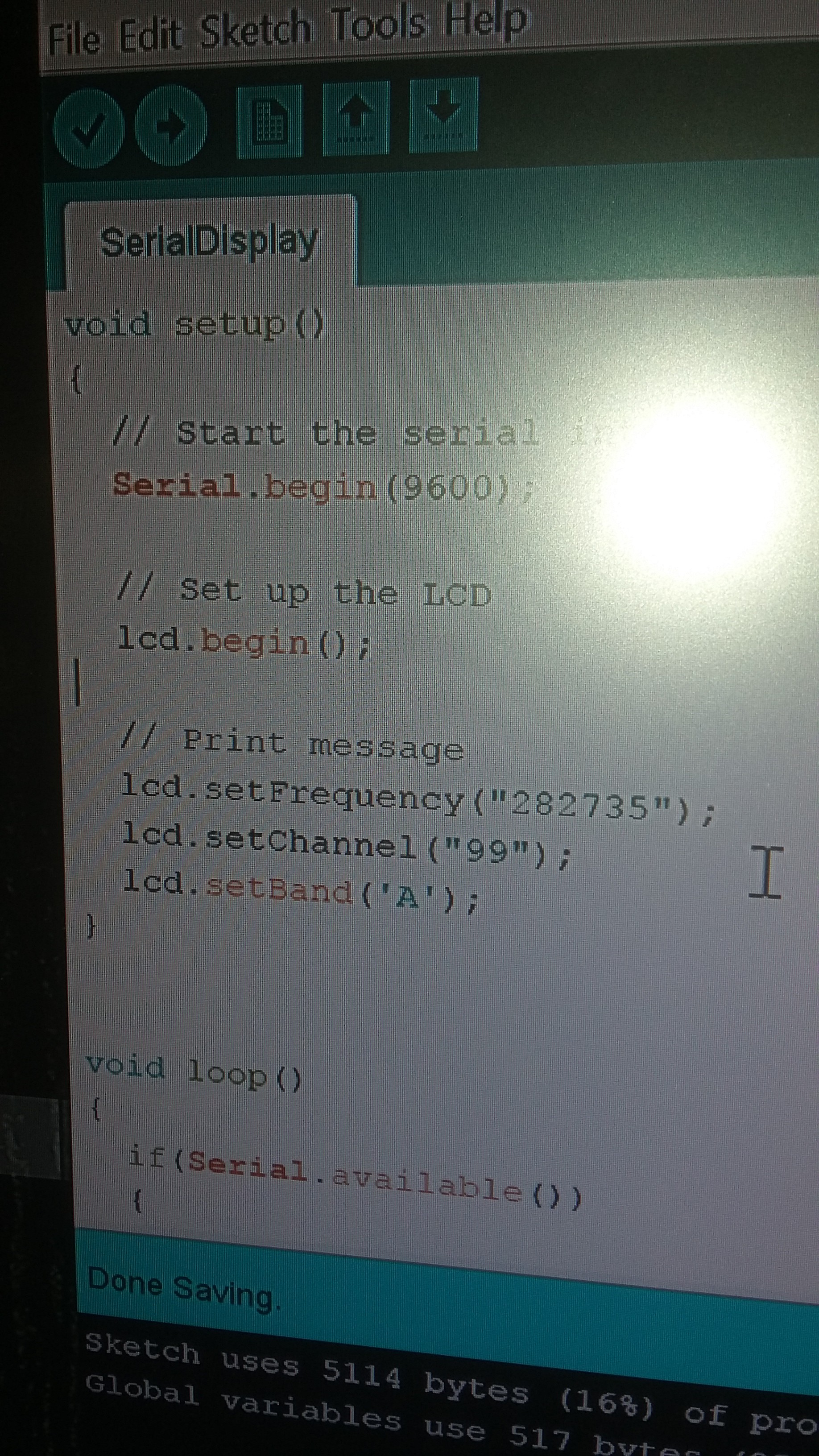
It does not work like the standard LCD libraries despite being based on some of that code. It implements a set of methods that are specific to the HR2510 and the things it can display. I expect that there may be other versions of this library created with the same methods for Lincoln/2830, HR2600, TS-5010, CBS-1000, and other variants not listed. Some of the parts between those radios may be more easily interchanged with inexpensive adaptor boards through this project.
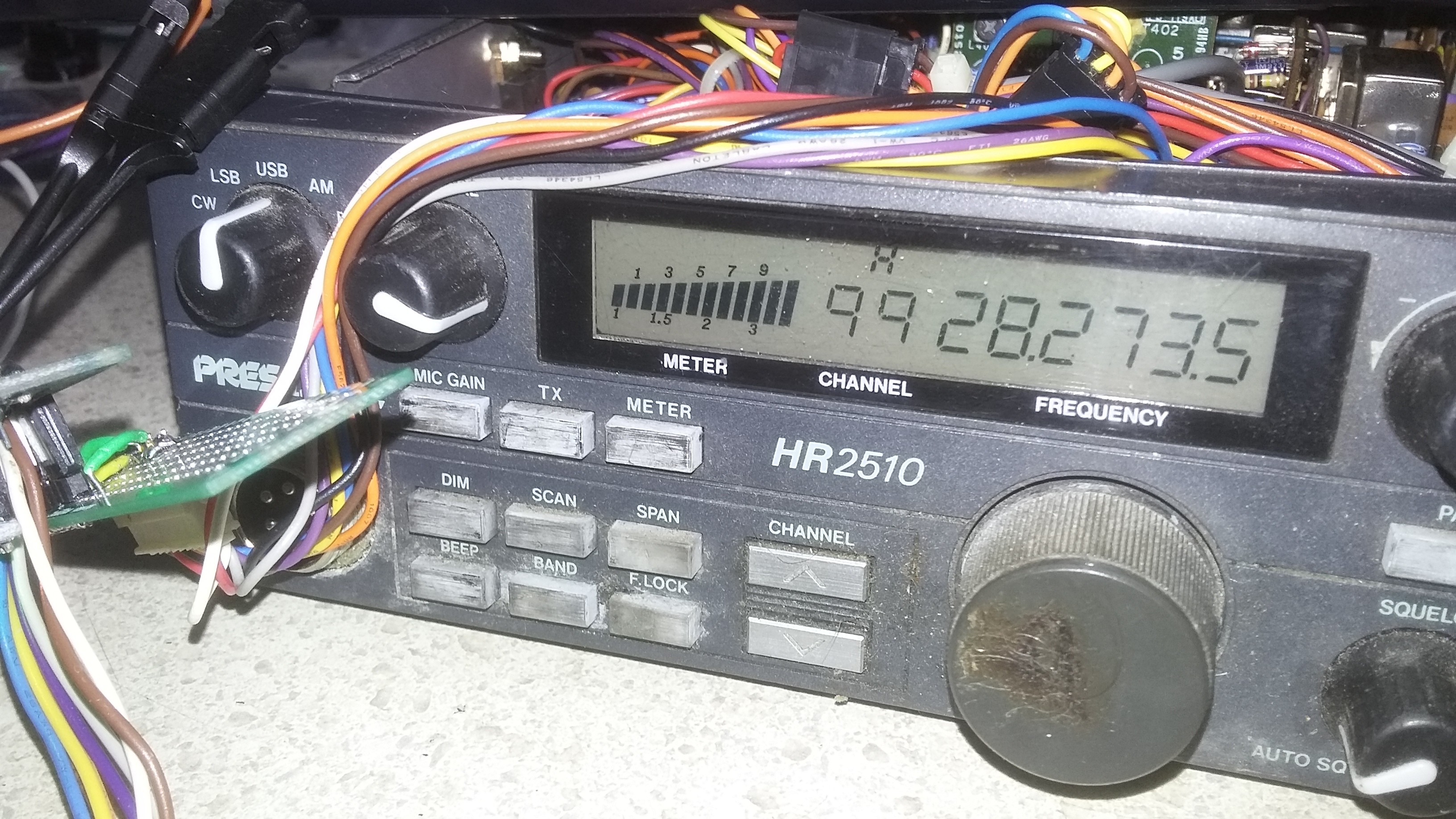
PB112 Library Master Mode Example![]() Pardon the crusty old HR2510 that has been beating around in the truck for a decade or so. But do notice that the above code is driving the display.
Pardon the crusty old HR2510 that has been beating around in the truck for a decade or so. But do notice that the above code is driving the display.![]()
-
FM Modulation in Software
06/08/2017 at 00:18 • 1 comment
PB121
A project to replace the Uniden PB121, PB112 boards with modern counterparts to revive dead radios and overcome mcu limitations.
 David L Norris

 Pardon the crusty old HR2510 that has been beating around in the truck for a decade or so. But do notice that the above code is driving the display.