 big_red_frog
-
Assembly order
02/10/2016 at 01:50 • 0 commentsNoting I don't cover magnet inserts in these images, it is just a quick and dirty assembly order for a helmet made with large parts. plastic inserts for back fan and lights are also not shown.
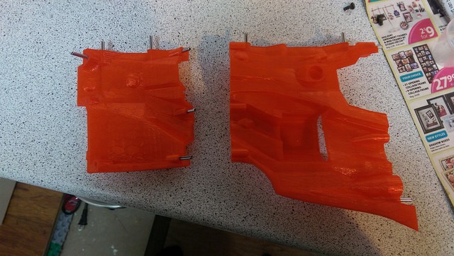
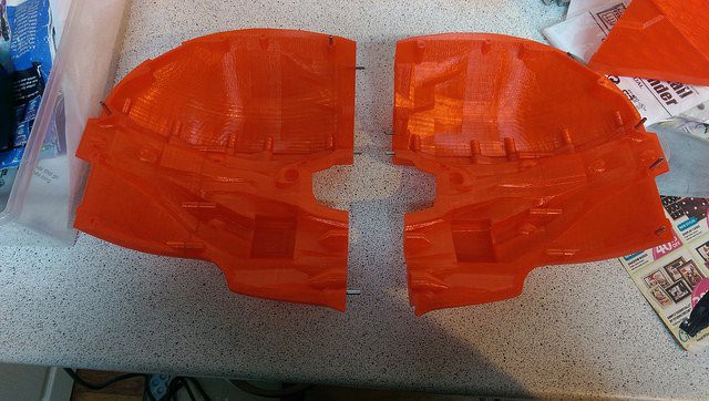
Start with a jowl and rear bottom piece
![]()
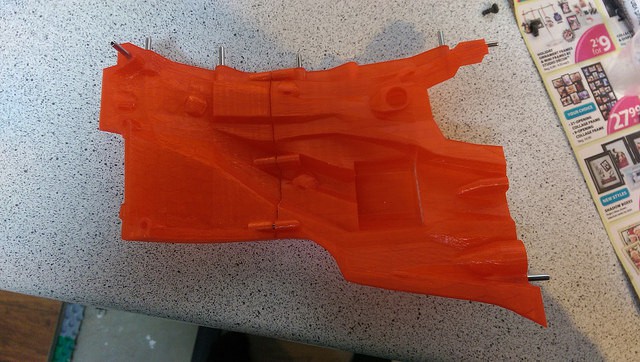
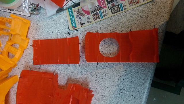
Attach together
![]()
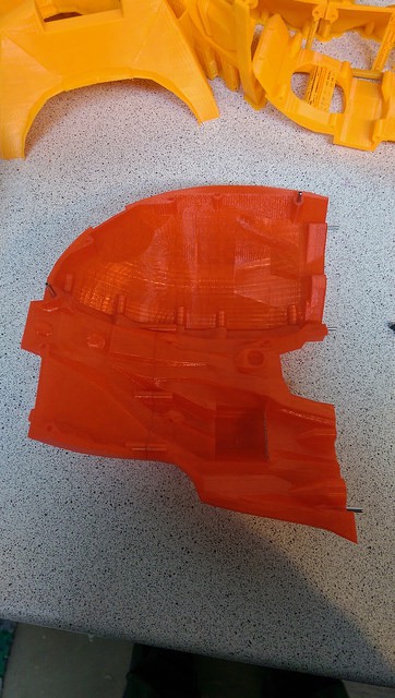
next take a temple and top piece, in this case a printed as a single large part
![]()
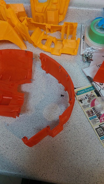
Attach to form a full side
![]()
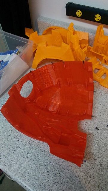
Repeat for other side
![]()
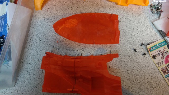
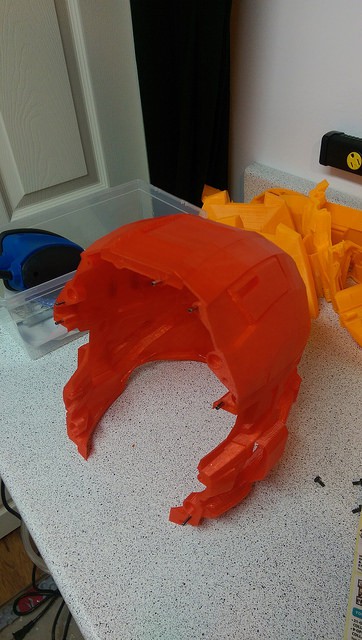
Now take the roof and back piece, ( back fan and back bottom printed as one large piece )
![]()
Attach to made one long center piece
![]()
Add a full side as assembled previously
![]()
Then the other side
![]()
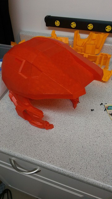
Add the peak
![]()
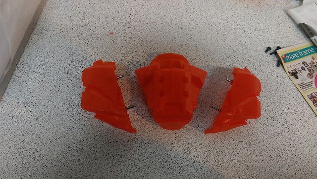
Now take the three chin pieces
![]()
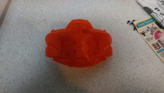
Assemble
![]()
Attach to main helmet
![]()
-
Addition parts for the Adult Size A
03/04/2014 at 03:43 • 0 commentsIf you are going to print the Size A, you need to understand which extended design parts are available to print...
The size A evolved as I worked the design, there are additional parts available that are either exclusive to the size A or have otherwise been combined into the base model for the size B and C
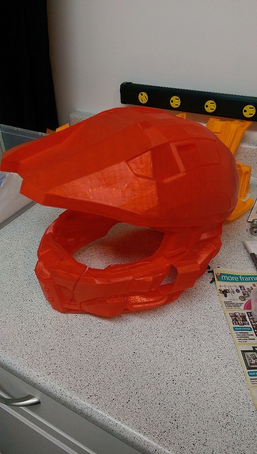
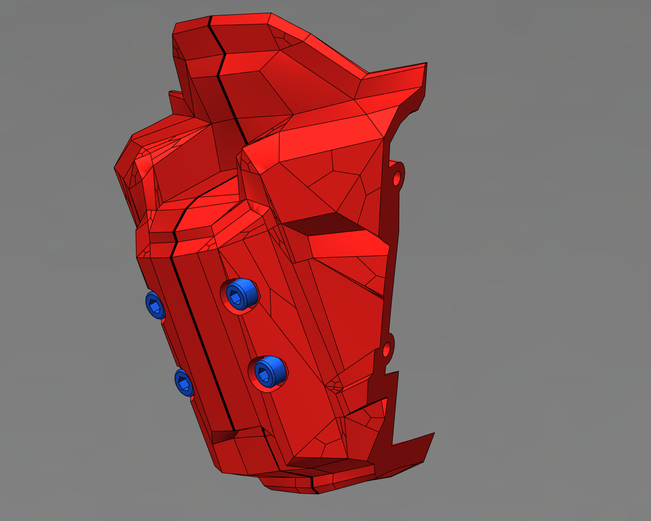
Chin Front with M4 bolt modifications - Those M4 Hex heads really up the game. http://www.thingiverse.com/thing:163439
![]()
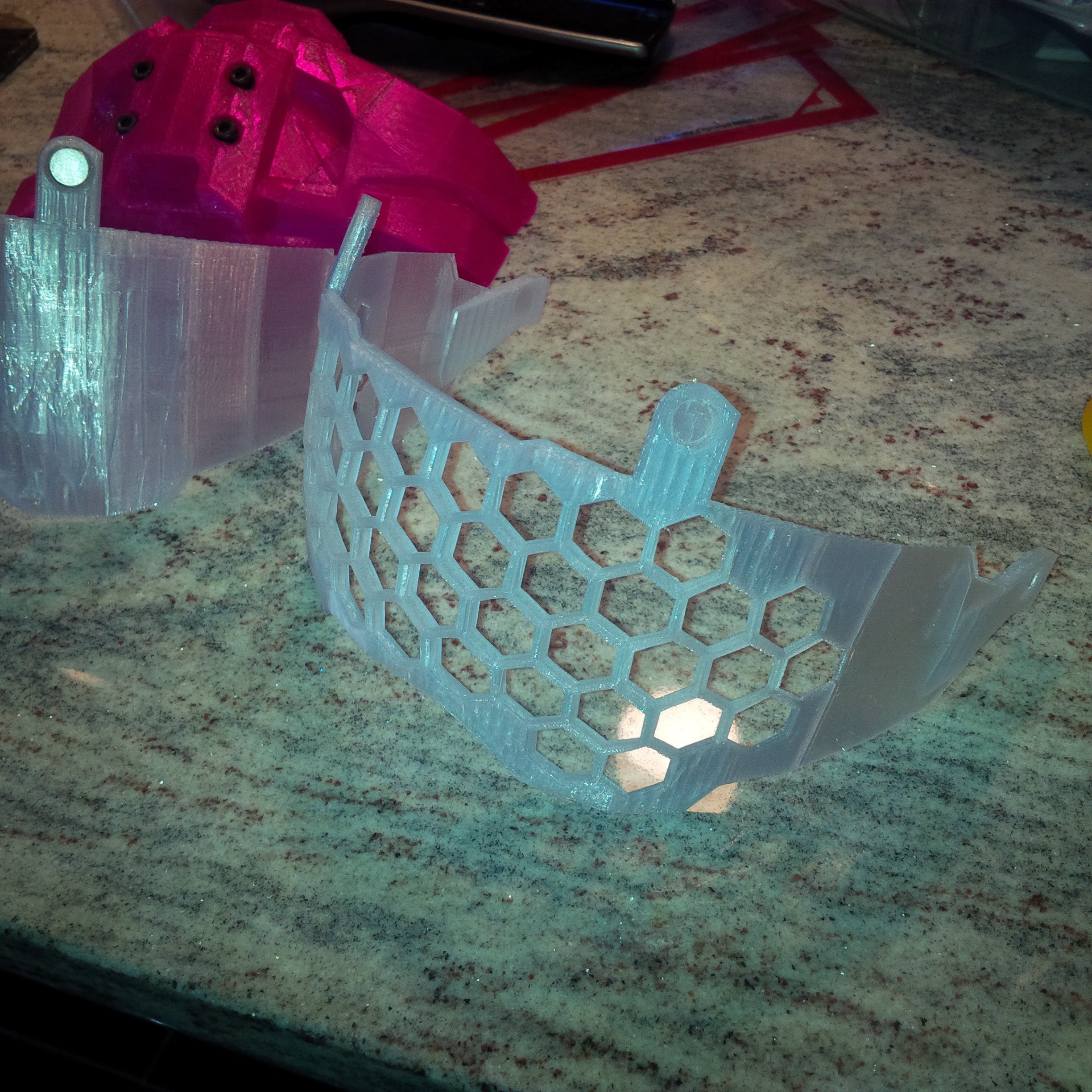
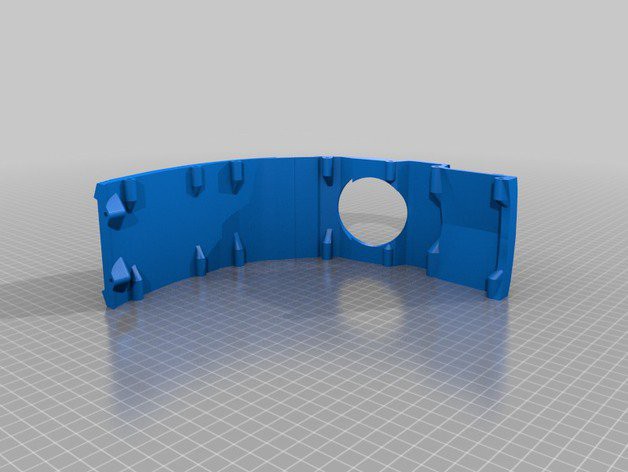
Perforated Visor for Halo Helmet - want to be able to see through a printed visor?
http://www.thingiverse.com/thing:165110
![]()
Halo 4 Helmet Size A Big Pieces - Combined components where separation was unnecessary if you have a replicator 2 size build volume. http://www.thingiverse.com/thing:168678
![]()
Halo 4 Helmet Full Size A with tiewraps - take control of that wiring harness, with built in tie wrap "warts" in the inside of the model.
http://www.thingiverse.com/thing:169295
![]()
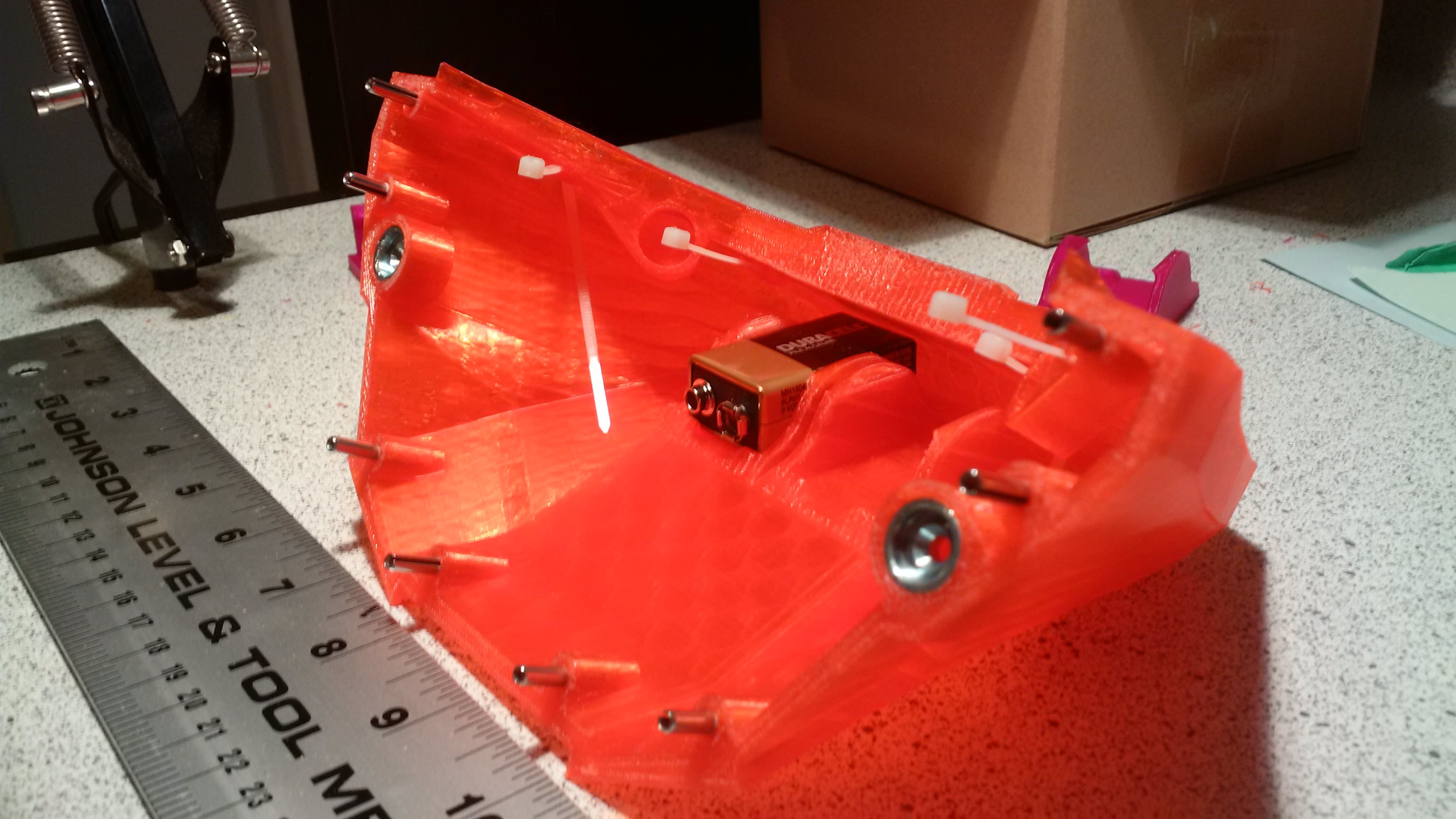
Halo 4 Helmet Full Size A Peak with Batteries - you need somewhere to put those 9 volt batteries, and these built in clips rock. http://www.thingiverse.com/thing:171912
![]()
Want a PETG vac formed clear visor ready for painting in your favorite metallic?
http://www.thingiverse.com/thing:217267
![]()
-
Wire routing with tie wraps
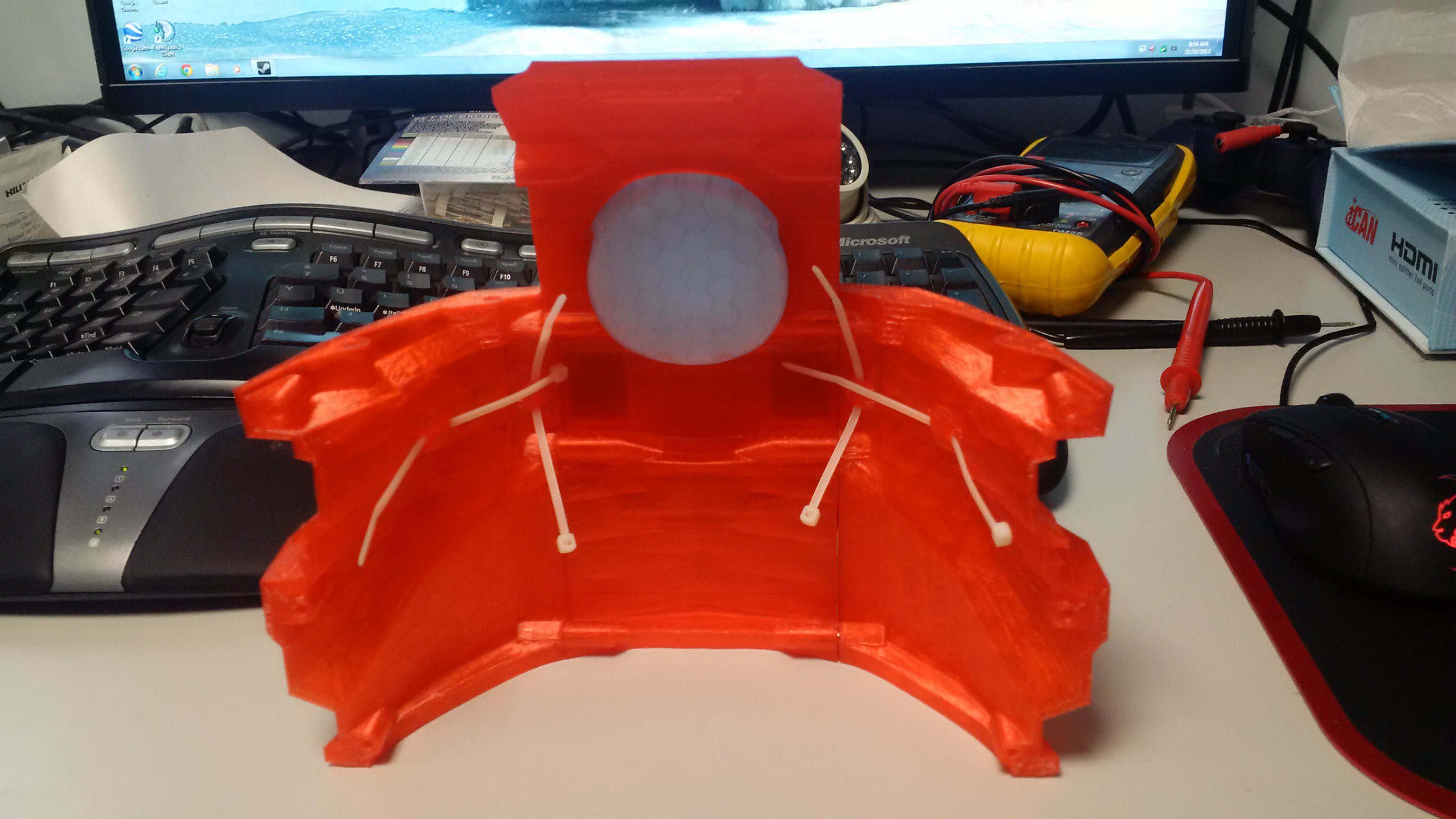
03/02/2014 at 22:03 • 0 commentsPrint in place tie wrap mount points for wiring guides
Note the parts at http://www.thingiverse.com/thing:169295 and
http://www.thingiverse.com/thing:171912
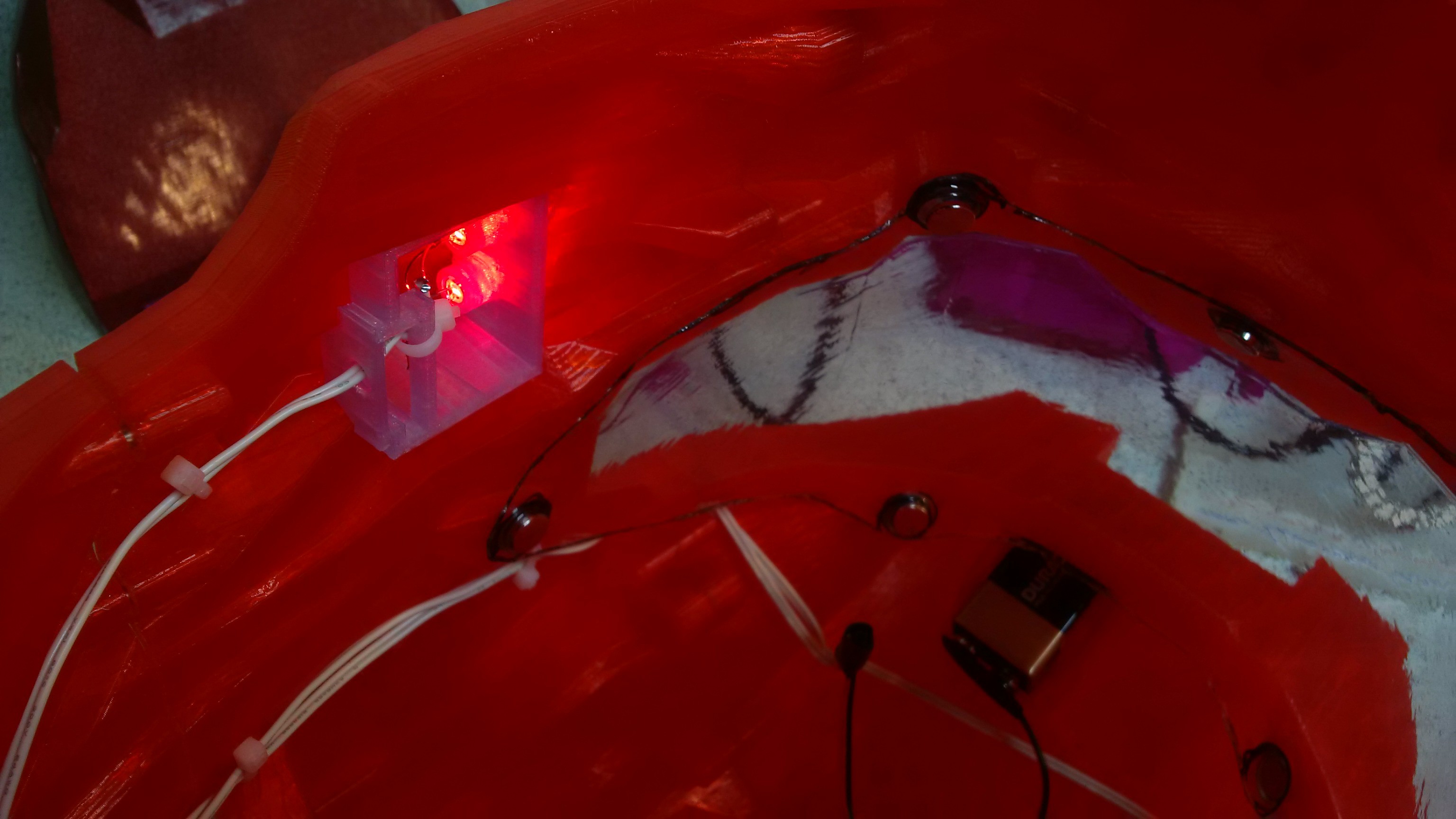
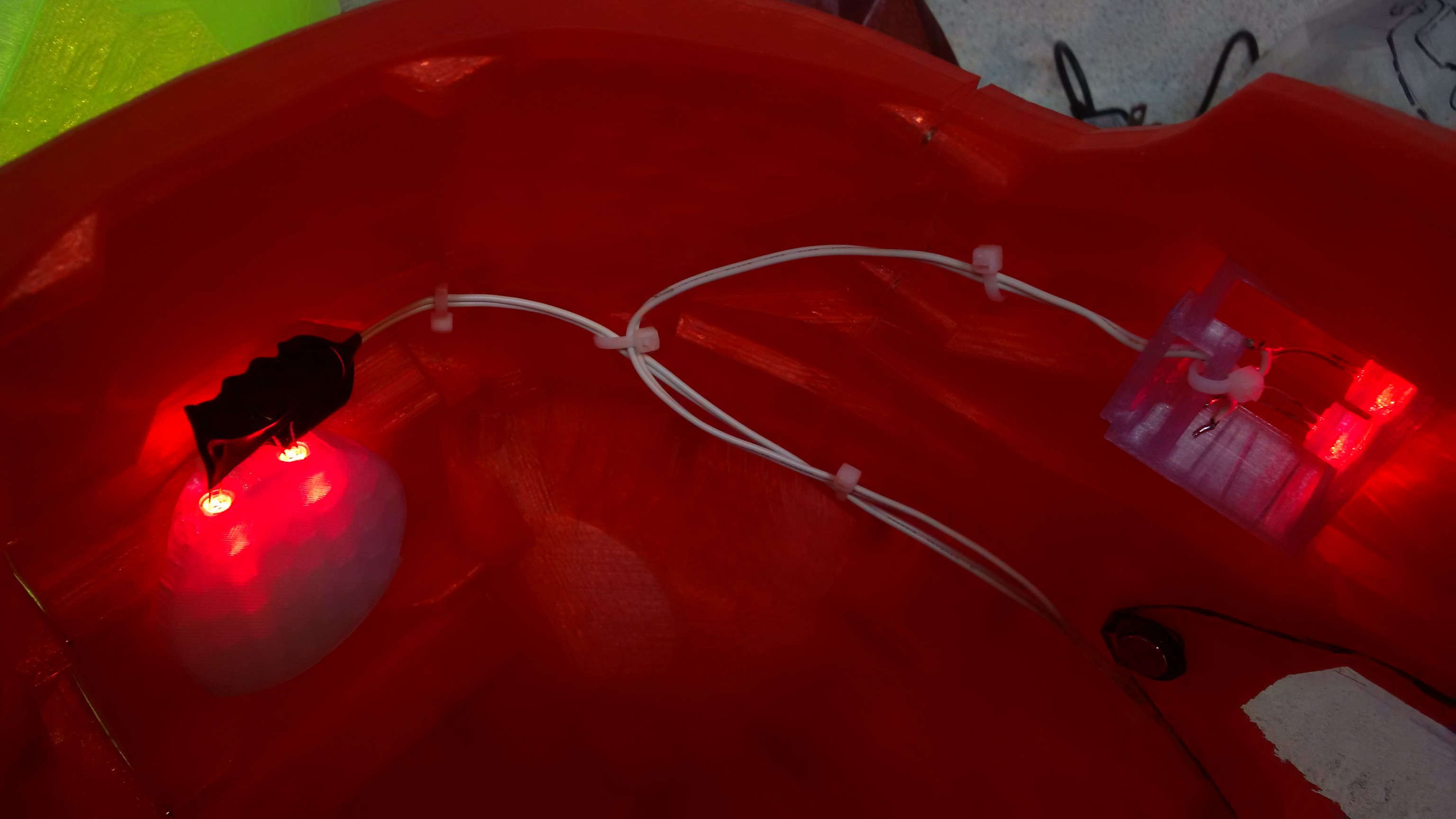
Are replacement parts for the size A model. They were designed after the main model was completed. Size B and C have all these features in there base model already. They have simple "warts" in the walls to allow the insertion of tie wraps, you can then use these to route the wiring from the jowl and rear insert LED's up to the 9 volt battery in the peak which mounts in a print in place sprung clip. ![]()
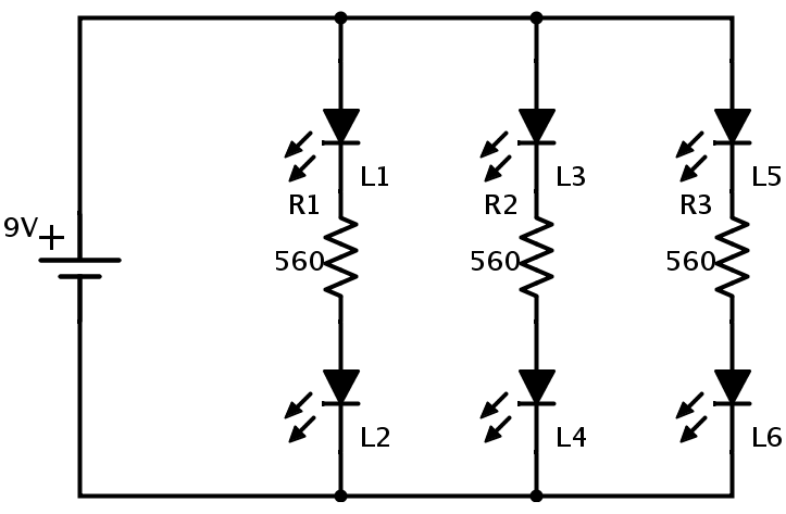
The present lighting circuit is very simple, soldering the resistor in series with each pair of 5mm LEDs. The resistor can sit directly between the LED's themselves, which makes soldering the twisted pins easy.
![]()
Here is a Jowl Led insert, two 5mm LED's and a suitable current limiting resistor in series back to the 9 Volt battery. ![]()
Here are the rear insert LEDs, with contacts taped off. Same combination of two 5mm LED's and a current limiting resistor.
Note all three pairs, 2 Jowls and the rear insert are wired in parallel to the 9 volt.
![]() Here is the Jowl on the other side, which wires straight to the peak to join up with the other runs.
Here is the Jowl on the other side, which wires straight to the peak to join up with the other runs.![]() I originally put an in line switch in the design, but it was more trouble than it was worth, and pulling the battery connector off is the preferred form of control at this time...
I originally put an in line switch in the design, but it was more trouble than it was worth, and pulling the battery connector off is the preferred form of control at this time... -
Tension pins and cleaning out the pin holes
03/02/2014 at 14:56 • 0 commentsThe use of tension pins allows components to be accurately aligned for gluing or in use assembly such as the chin parts.
This also allows you to print split surfaces as flats, which helps.
I have used tension pins purely because I knew I could get them. 3mm filament is close enough to 1/8 inch diameter, so you could just as easily cut lengths of such to use, or any other material with a nominal 1/8 diameter.
Two lengths have been used in the various models.
Size A Adult uses 3/4 inch pins throughout as per 240-025 - 57 off, just buy a box of 100 from your local hardware supplier, I get mine from Spaenaur here in Canada. These are stainless and shiny, not necessary, but, they ARE shiny... http://www.spaenaur.com/pdf/sectionE/E107.pdf
Size B Medium and Size C child uses 5/8 inch pins throughout, as per
240-008 at the same link above, 46 off, again just buy a box of 100. T hey are a little shorter and fit in the curves more easily when remodeling down to size. There are fewer pins in these sizes, as many of the parts are combined as they now fit in the print area of a replicator 2. They can also be bought from Amazon, not sure on those prices and delivery though. ( really, find a local hardware supplier, a real one, not a big box store who will happily charge you a dollar for 2! )
3/4 length. http://www.amazon.com/Tension-Pin-20-pieces/dp/B00... 5/8 length http://www.amazon.com/Tension-Pin-20-pieces/dp/B00...
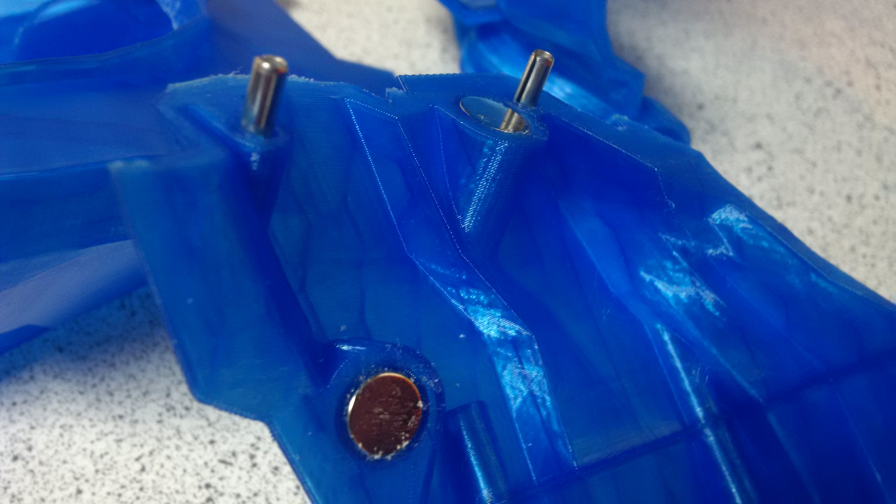
Here is a picture of a 5/8 pin next to a magnet and coin for scale, no banana was available at the time.
![]() When printing with support it is likely that various holes in the model will end up with webbing inside them, if they are horizontal or facing down, that's fine though, the material is intended to be removed, and should give, without damaging the main body.
When printing with support it is likely that various holes in the model will end up with webbing inside them, if they are horizontal or facing down, that's fine though, the material is intended to be removed, and should give, without damaging the main body.You will need a 1/8 diameter drill bit on a hex mount as per
![]() Stick it in a screwdriver handle for hex bits, and you have a grunging tool to get in and do some dentistry.
Stick it in a screwdriver handle for hex bits, and you have a grunging tool to get in and do some dentistry.![]() Then just push in to each hole and clear out the naughty plastic. Some will already be clear, some will be easy, some will have a personal vendetta against you. Start gently until you get the hang of it, if the bit is sharp, it should be doing the work. You should be able to feel when you bottom out, and try not to drill through the end of the hole and into the main body. Its not the end of the world, but try to avoid it!
Then just push in to each hole and clear out the naughty plastic. Some will already be clear, some will be easy, some will have a personal vendetta against you. Start gently until you get the hang of it, if the bit is sharp, it should be doing the work. You should be able to feel when you bottom out, and try not to drill through the end of the hole and into the main body. Its not the end of the world, but try to avoid it!![]()
Each pin hole is deeper than the pin needs to allow some detritus to be left, test fit a pin and make sure it goes at least half a length in. You can then pull them back out with pliers if necessary. In final assembly you will likely glue them in place.
![]()
-
Taking the rear insert to the NeoPixel Max
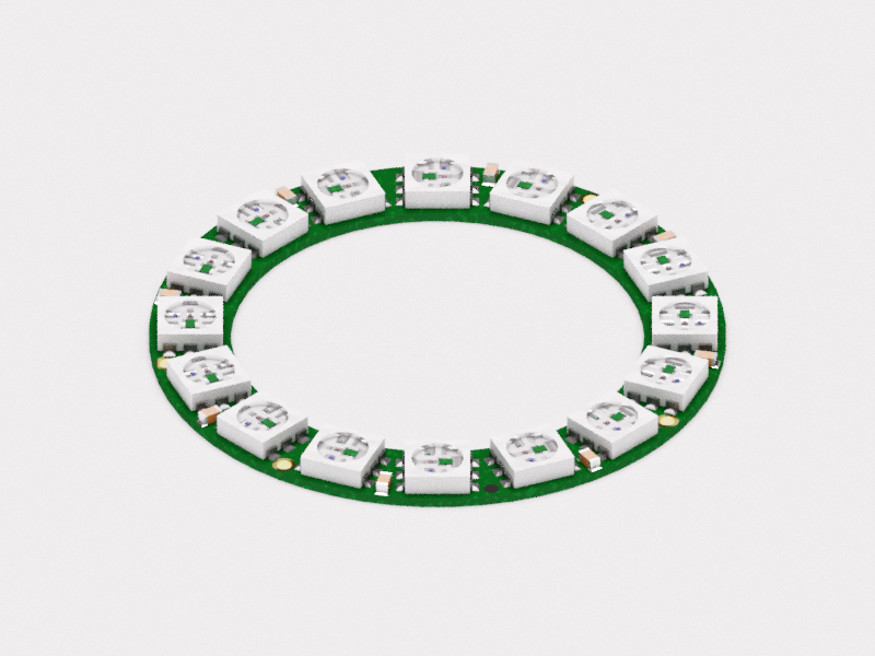
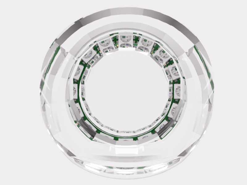
03/02/2014 at 03:19 • 1 commentFirst dimensionally accurate model a 16 led Neopixel ring from adafruit
to OCD level 1 because you can... http://www.adafruit.com/products/1463
The led https://fusion360.autodesk.com/projects/ws2812 The ring https://fusion360.autodesk.com/projects/neopixel-r...
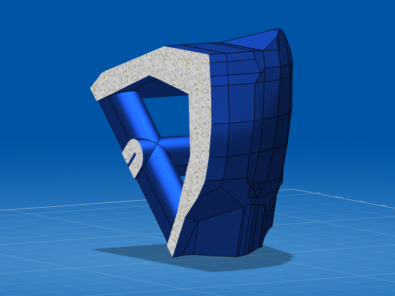
![]() Then define a body space gap with the model so you can use it as a boolean operator against the piece you wish to mount it in.
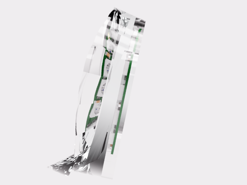
Then define a body space gap with the model so you can use it as a boolean operator against the piece you wish to mount it in.Design a test piece to test the body space fit.
![]()
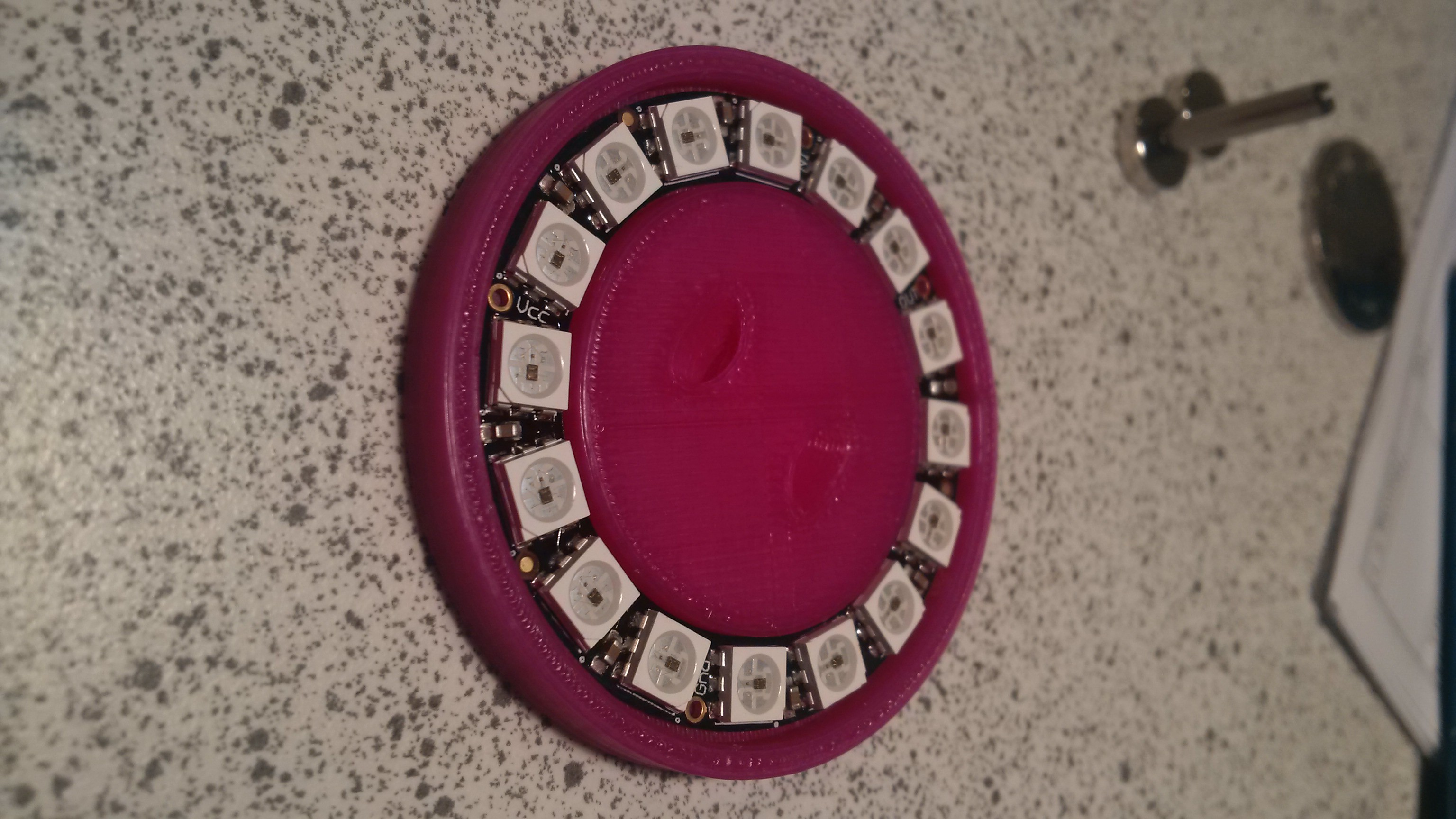
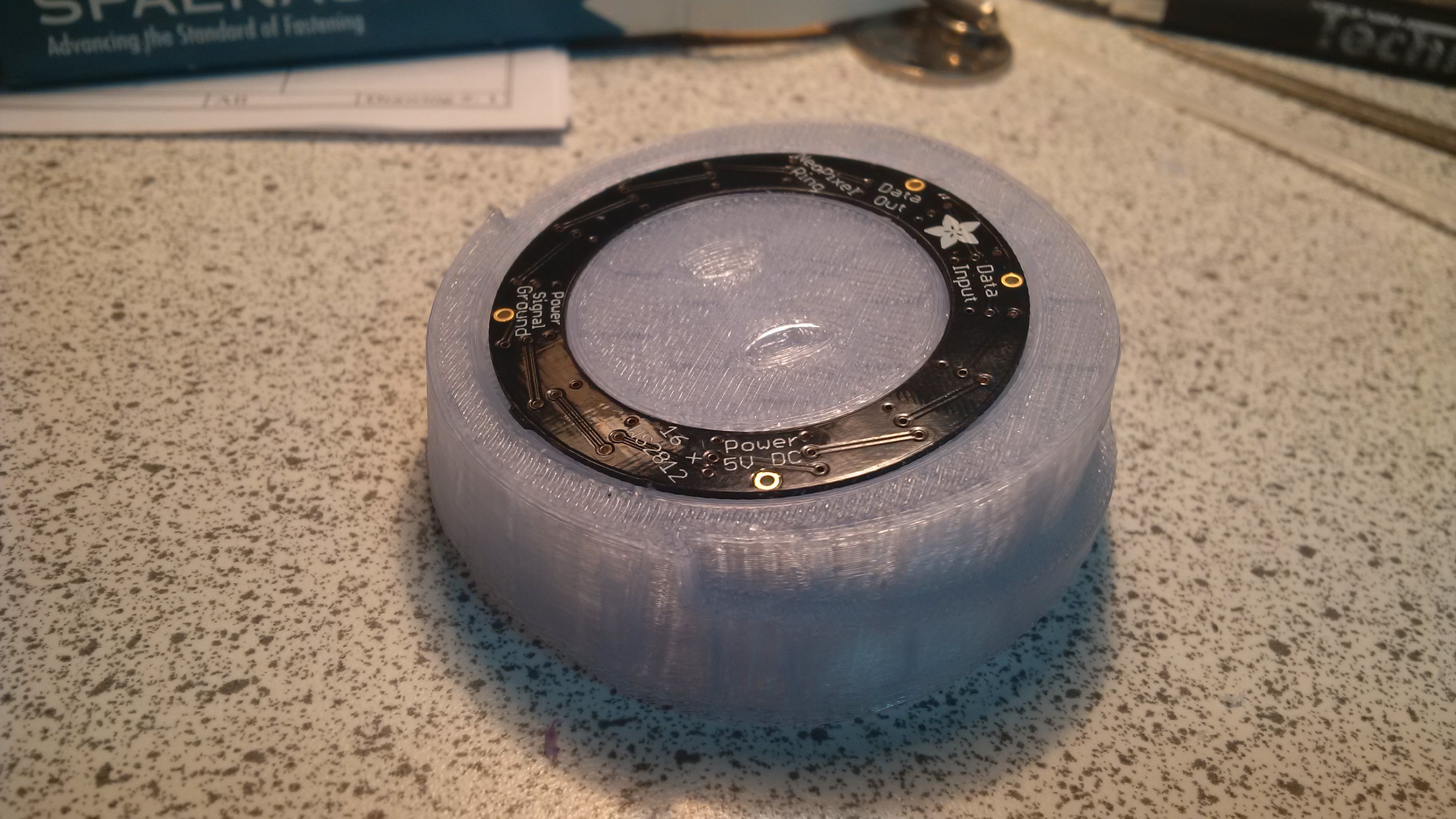
Print it, low material use compared to final part, so you can afford to iterate...Be amazed when it fits like a glove the first time.
![]()
![]()
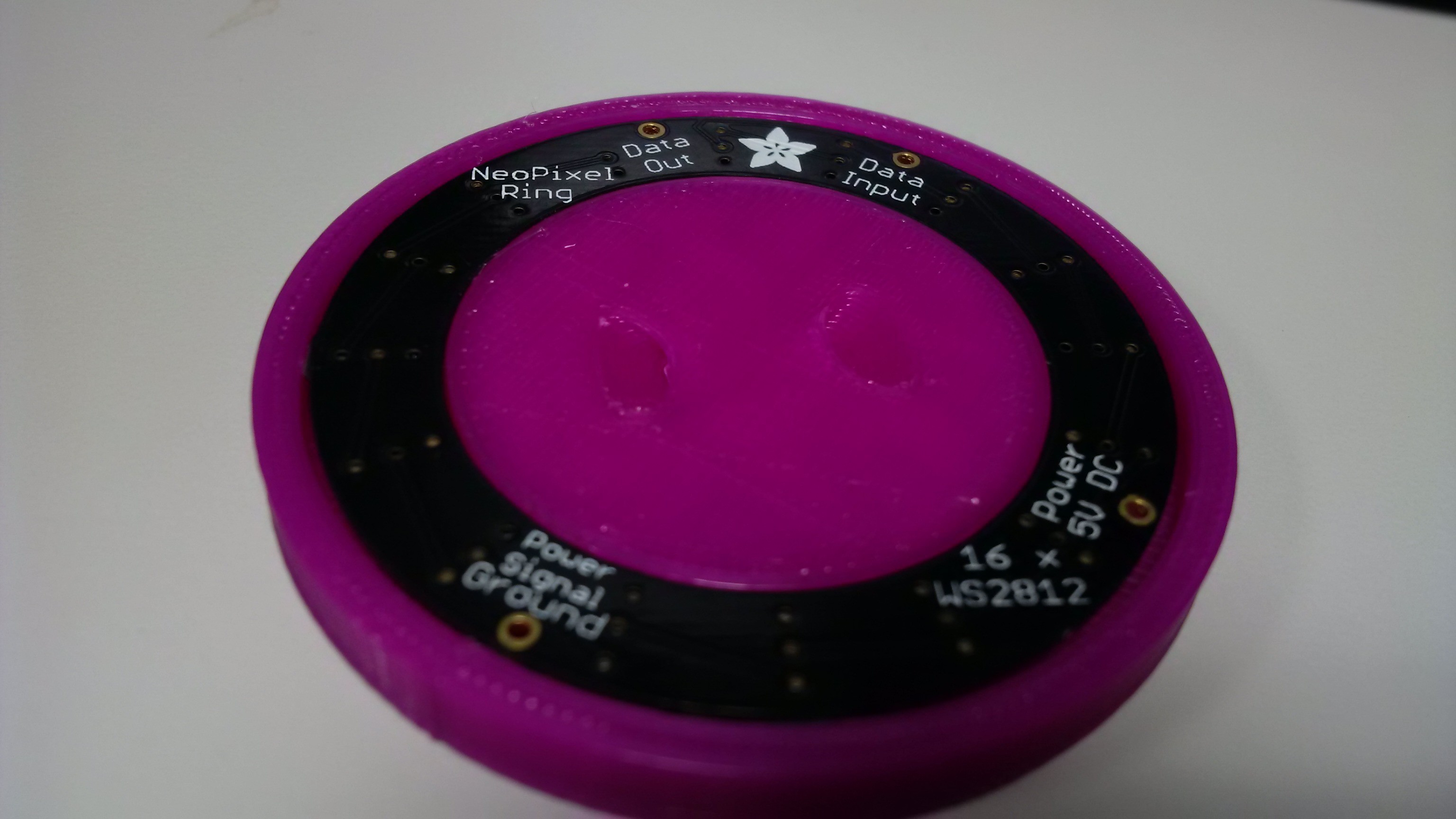
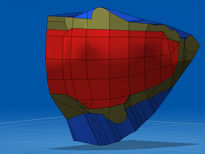
Model it directly into the target part...
![]()
![]()
Print it ready for integration. Shame the print is not quite as glassy... ![]()
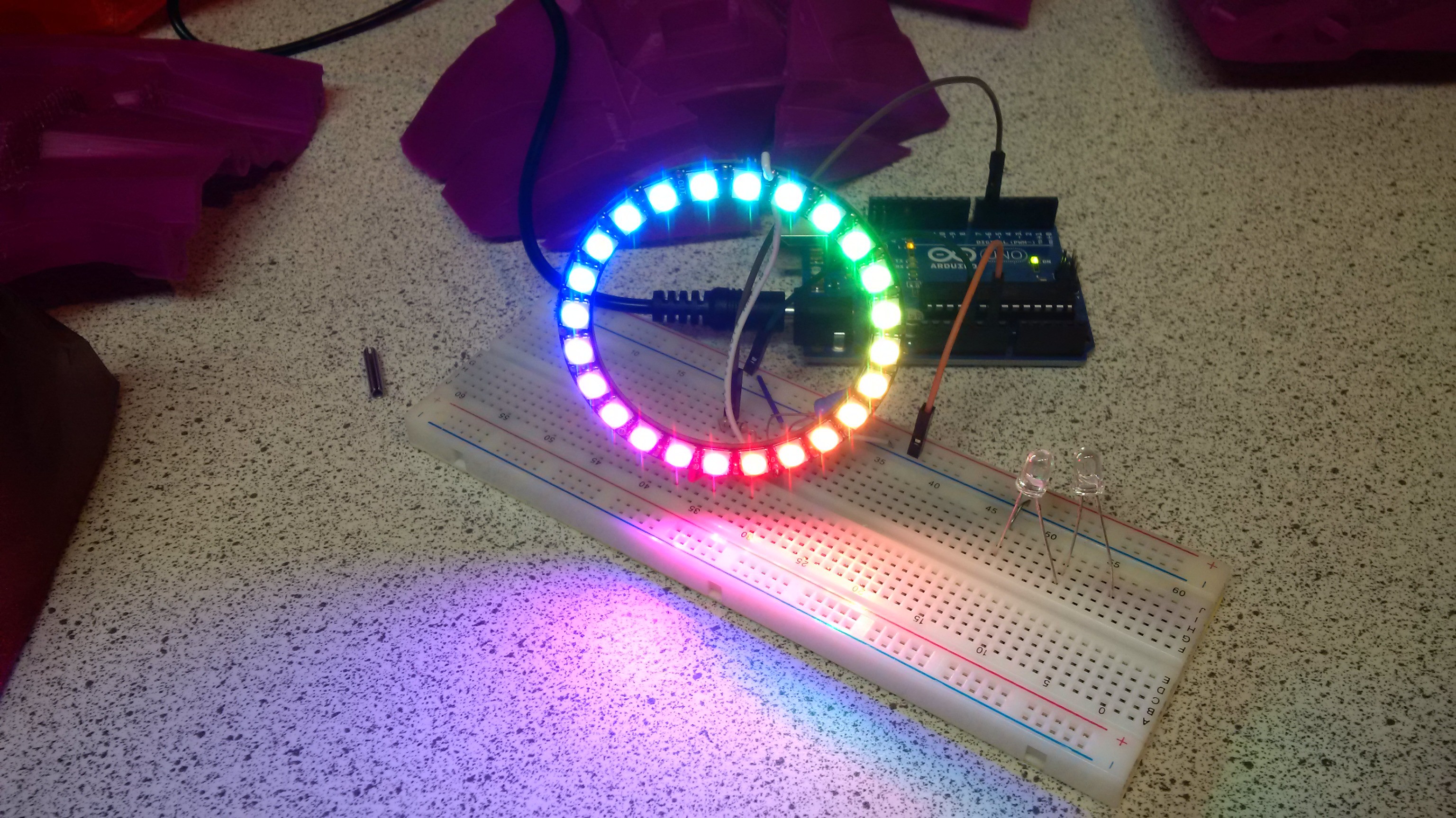
Prototype your electronics.
![]()
Stick it in and press go... Very hard to video.... No easier to video when in the helmet, trust me, it looks fab...
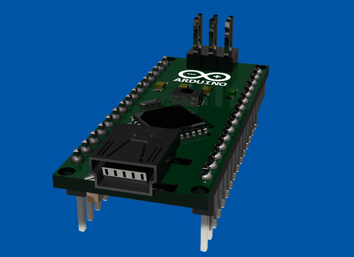
Of course this means I will have to place an Arduino nano into the helmet peak next to the 9 volt. Good thing i already have a model for that! ![]()
to be continued.
-
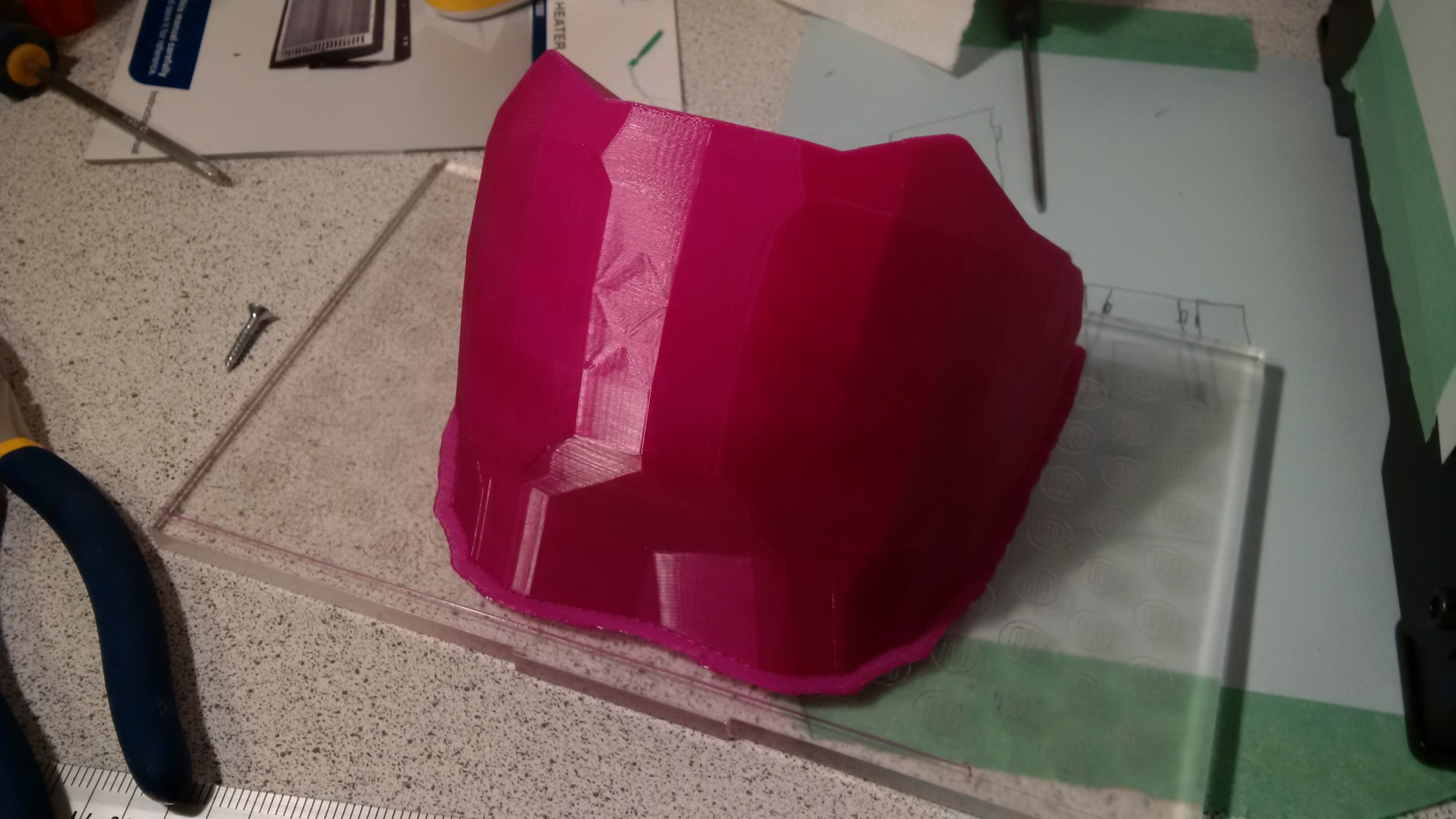
3D printed vac form mold for visor
03/02/2014 at 03:03 • 1 commentOriginal STL files are hosted in thingiverse at
http://www.thingiverse.com/thing:217267
As if by magic model a form for the visor in the original model. ![]()
Work out where your cut lines are
![]() By looking where it intersects the main model.
By looking where it intersects the main model.![]()
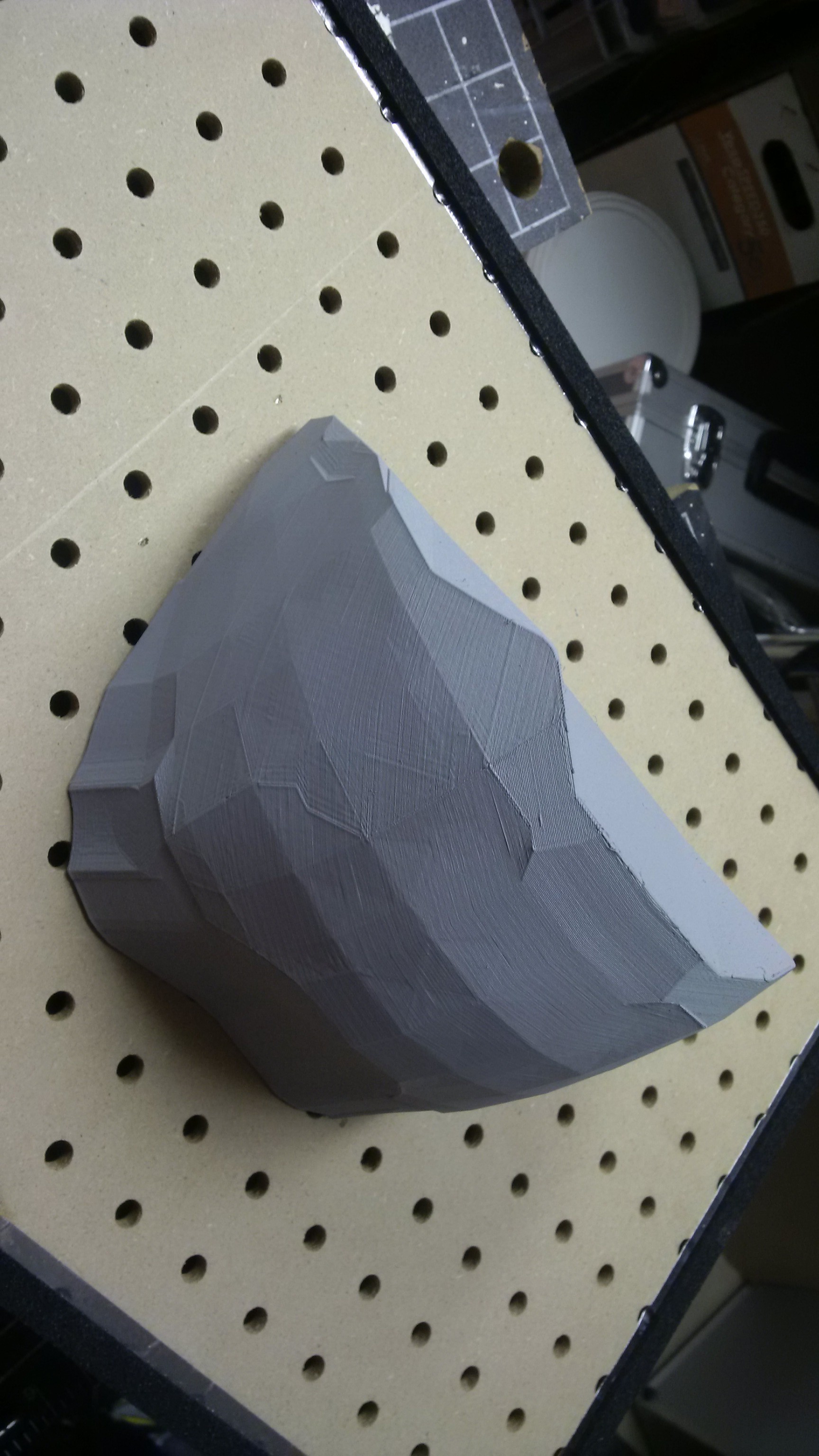
Once you have the model, print it.
![]()
Spray it.
![]() spray it some more
spray it some more![]()
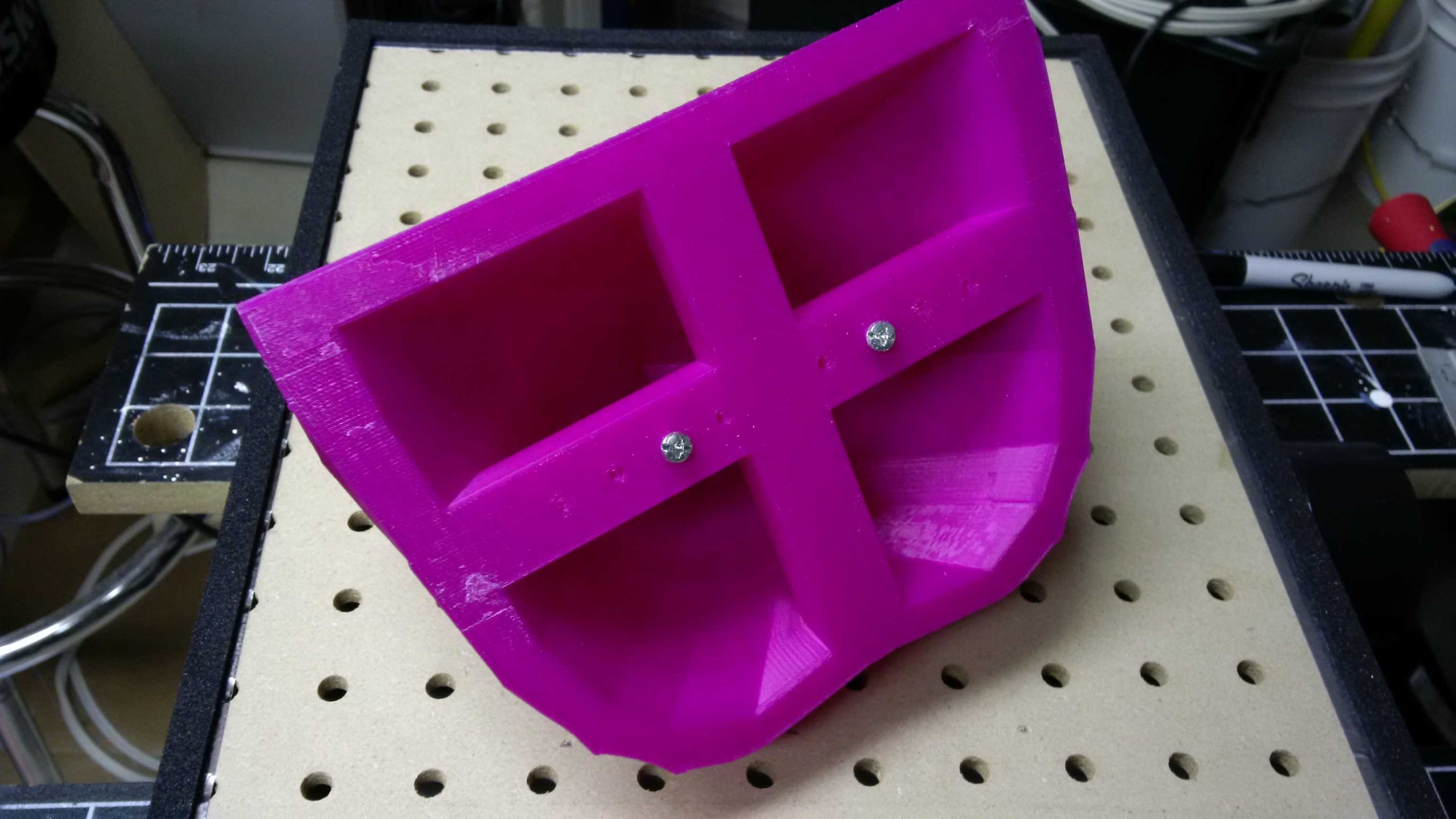
Have pull handles and screw locators for the peg board
![]()
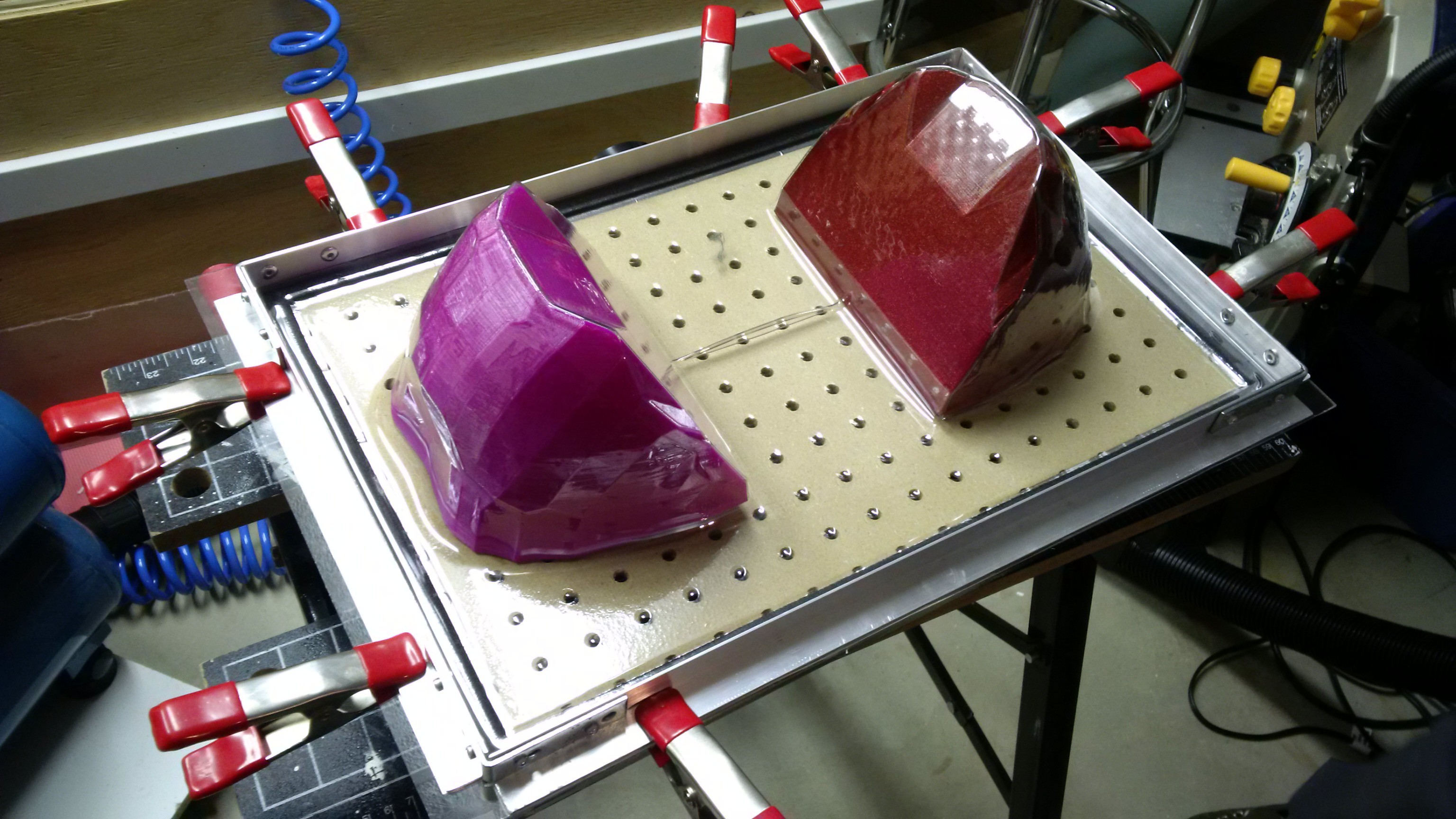
Then pull in pairs out of PETG so the webbing is on sacrificial areas, having first sprayed some furniture polish for easy release.
![]() But first of course heat it on a quartz heater hot box that you can collapse for storage and transport
But first of course heat it on a quartz heater hot box that you can collapse for storage and transport![]() remove the molds with a bit of compressed air down the side
remove the molds with a bit of compressed air down the side![]() Cut out with metal shears, its just safer, easier and more accurate than a band saw. Add magnets and drop in place.
Cut out with metal shears, its just safer, easier and more accurate than a band saw. Add magnets and drop in place.![]() Next step is to paint the visor, but that's another adventure...
Next step is to paint the visor, but that's another adventure...
Halo 4 Helmet ( Size A, B, C )
3D printable Halo 4 Master Chief helmet in various sizes...

 Here is the Jowl on the other side, which wires straight to the peak to join up with the other runs.
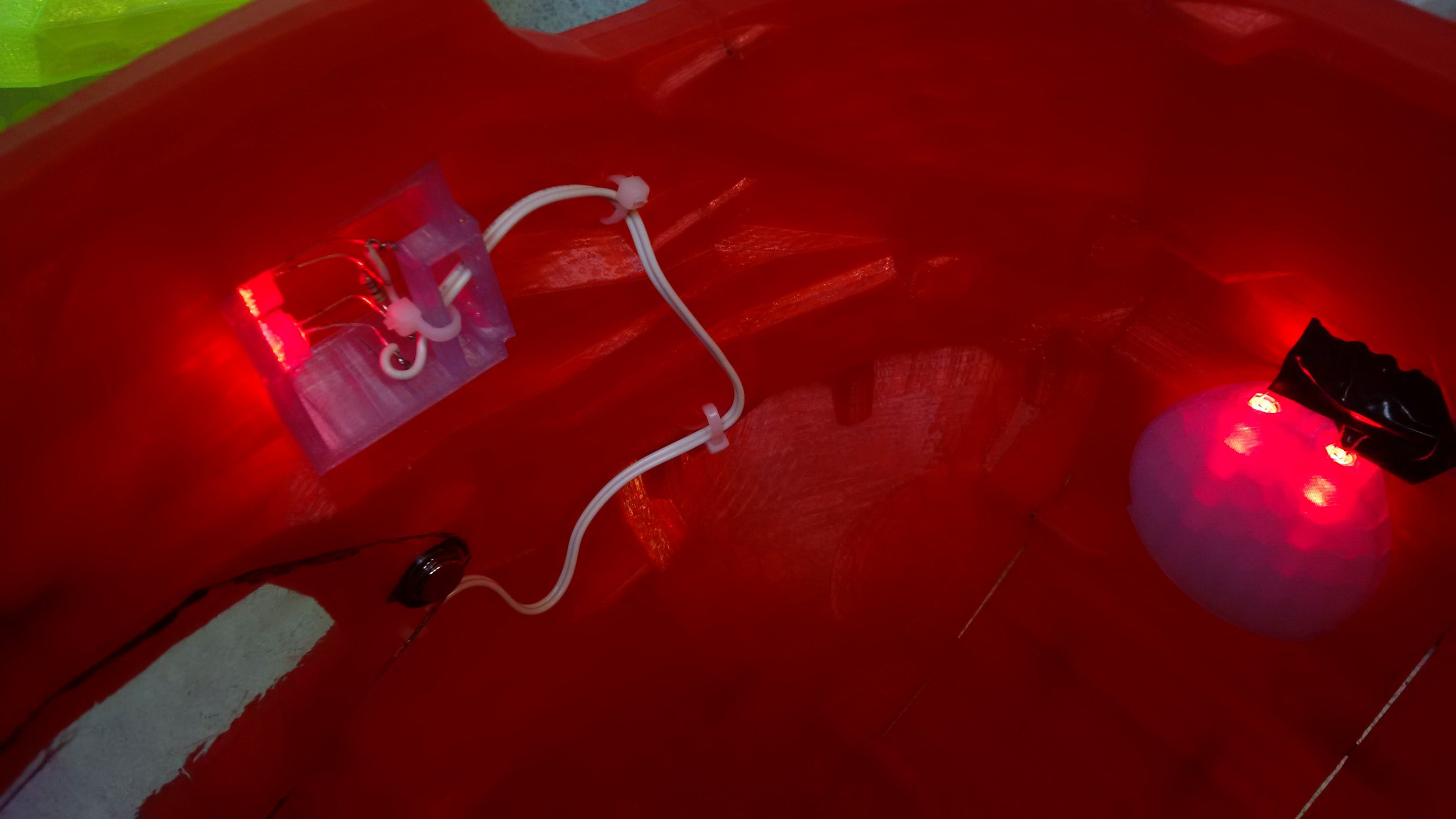 I originally put an in line switch in the design, but it was more trouble than it was worth, and pulling the battery connector off is the preferred form of control at this time...
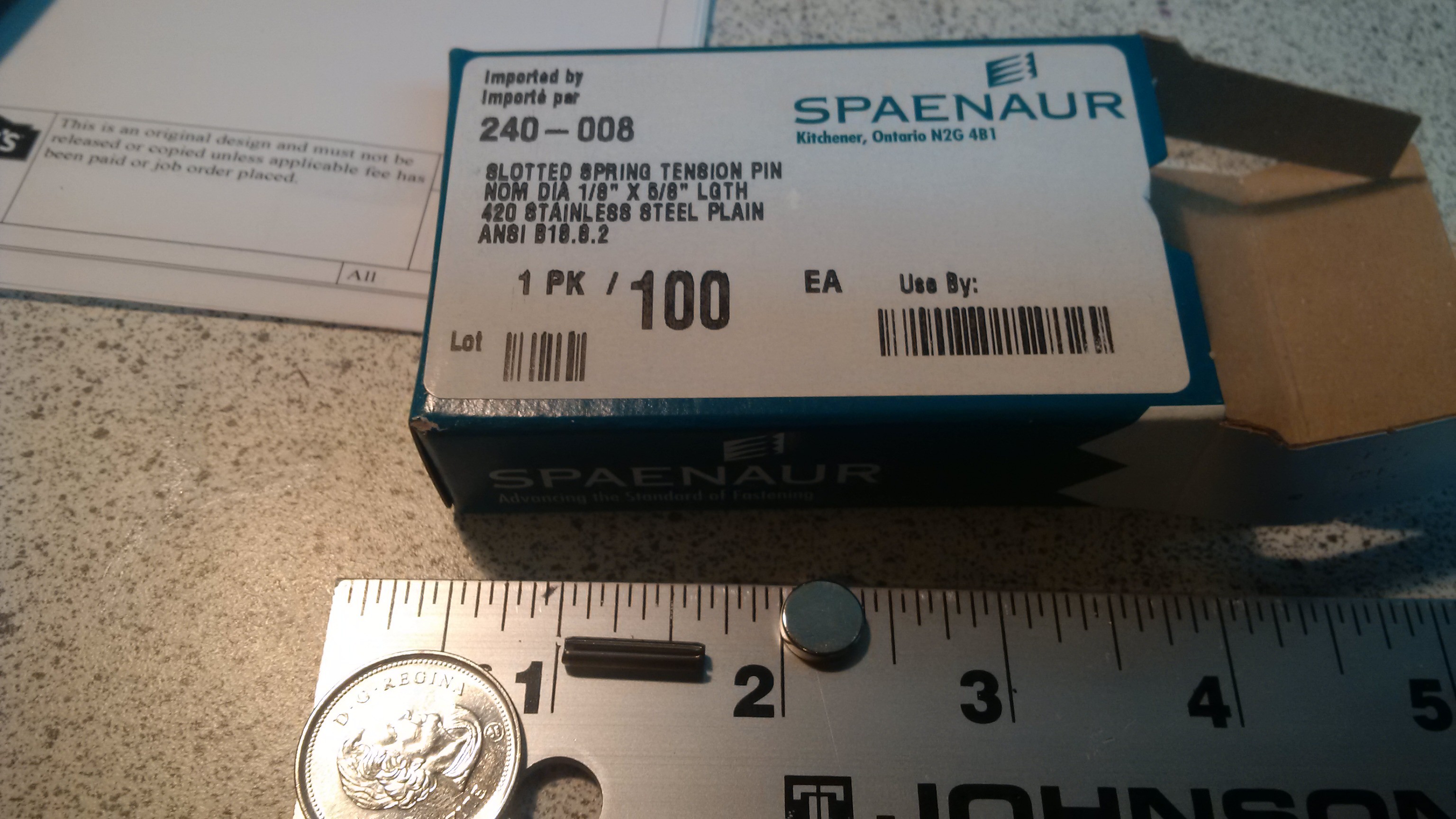 When printing with support it is likely that various holes in the model will end up with webbing inside them, if they are horizontal or facing down, that's fine though, the material is intended to be removed, and should give, without damaging the main body.
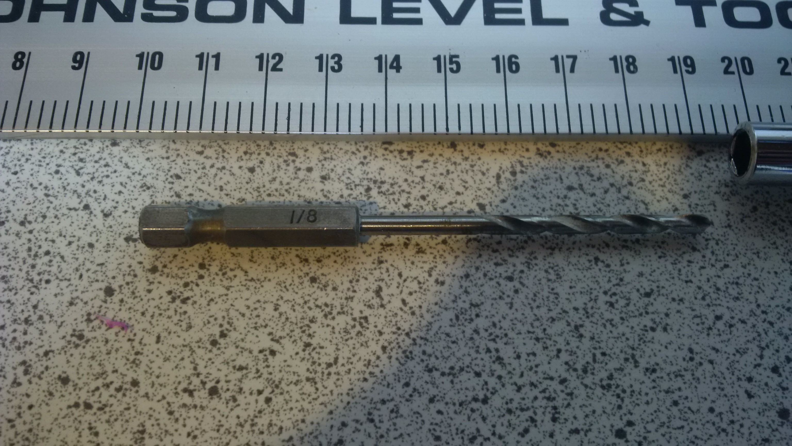 Stick it in a screwdriver handle for hex bits, and you have a grunging tool to get in and do some dentistry.
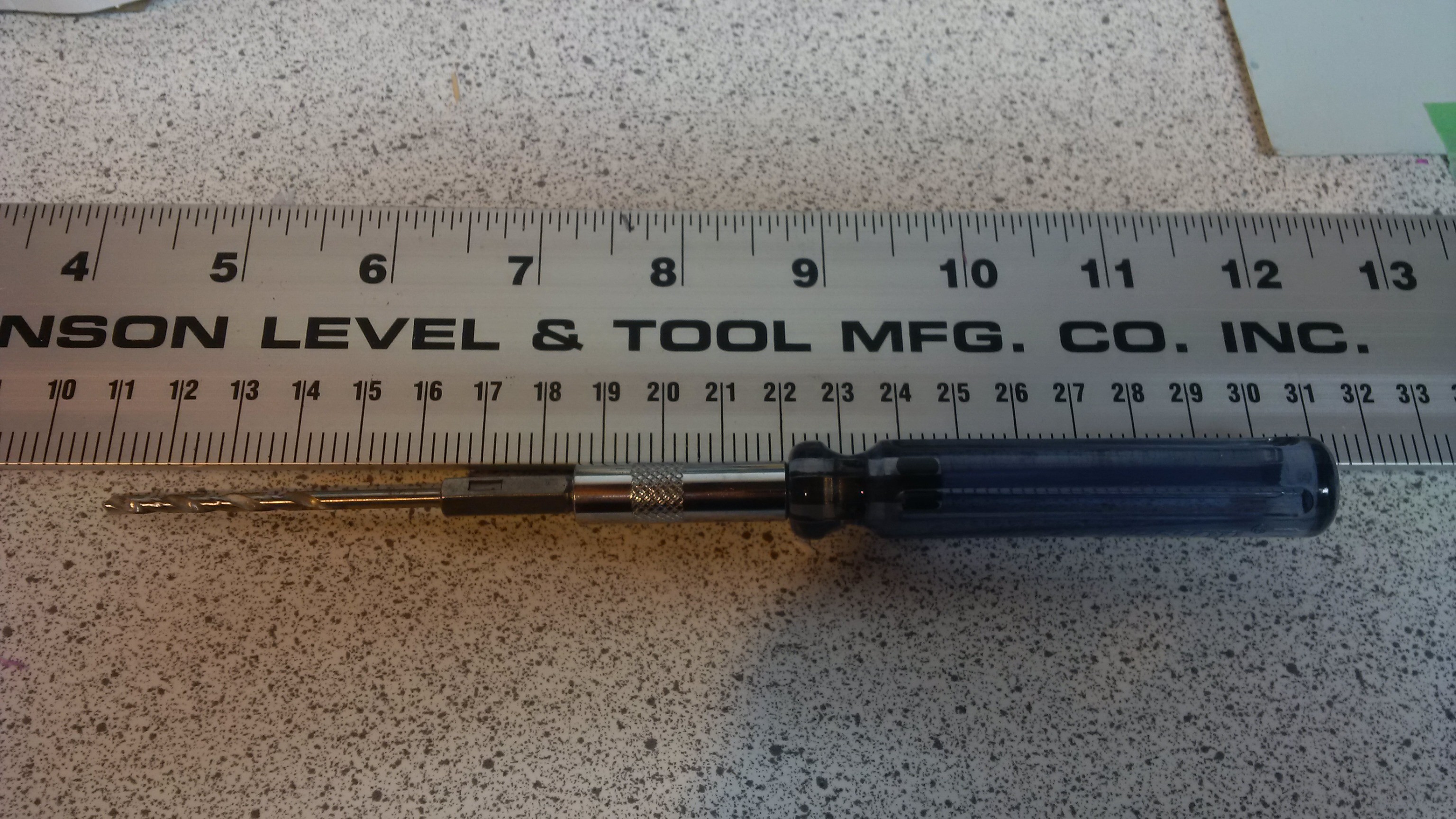 Then just push in to each hole and clear out the naughty plastic. Some will already be clear, some will be easy, some will have a personal vendetta against you. Start gently until you get the hang of it, if the bit is sharp, it should be doing the work. You should be able to feel when you bottom out, and try not to drill through the end of the hole and into the main body. Its not the end of the world, but try to avoid it!
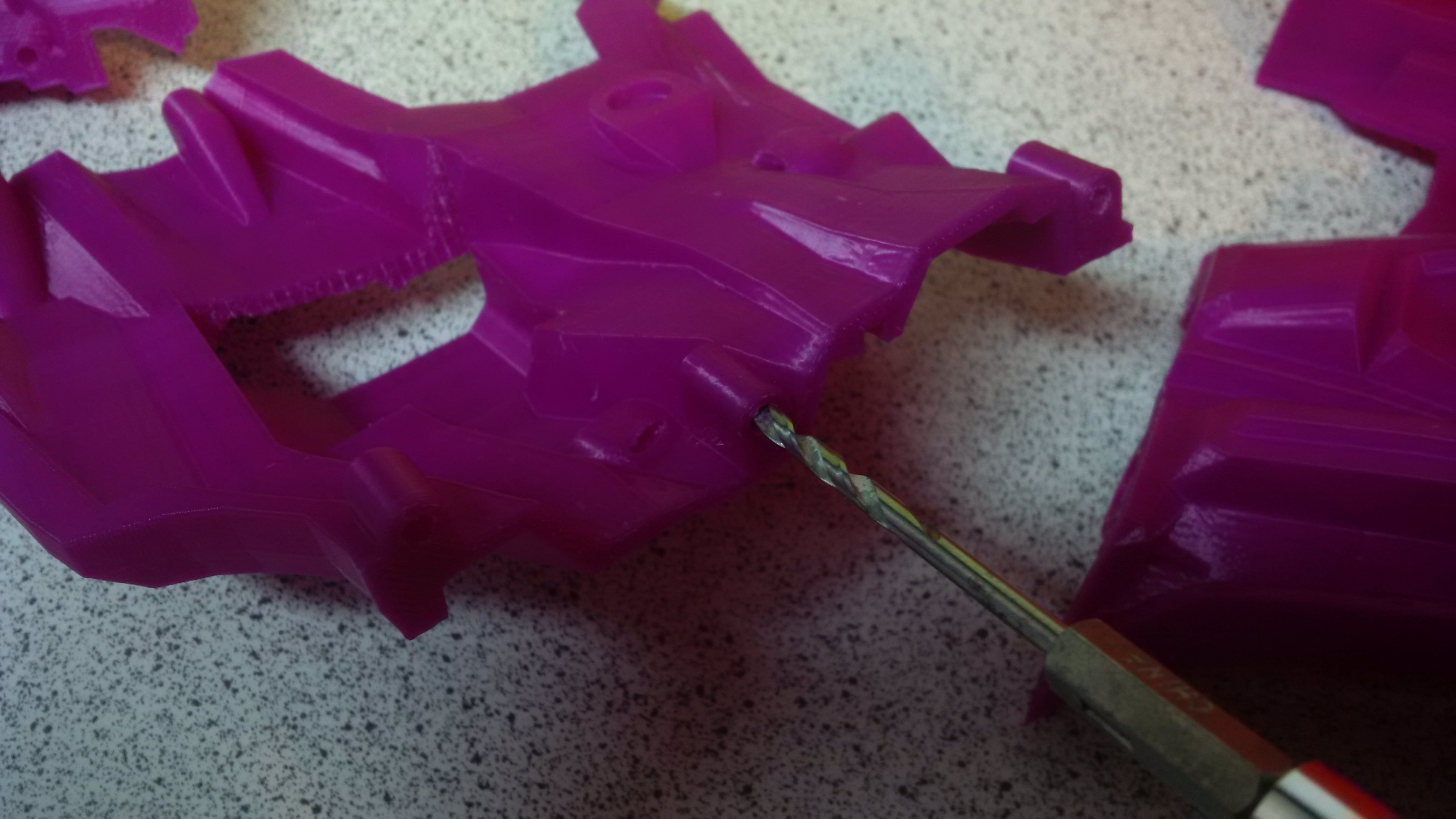
 Then define a body space gap with the model so you can use it as a boolean operator against the piece you wish to mount it in.
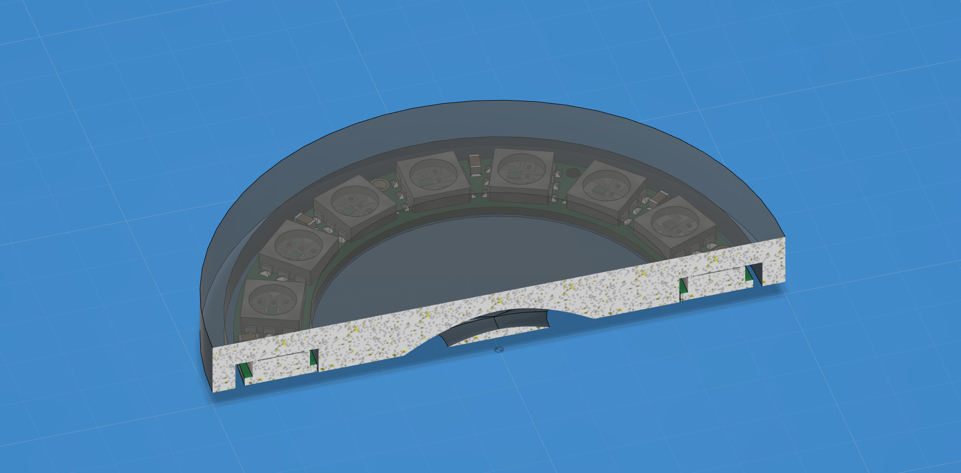
 By looking where it intersects the main model.
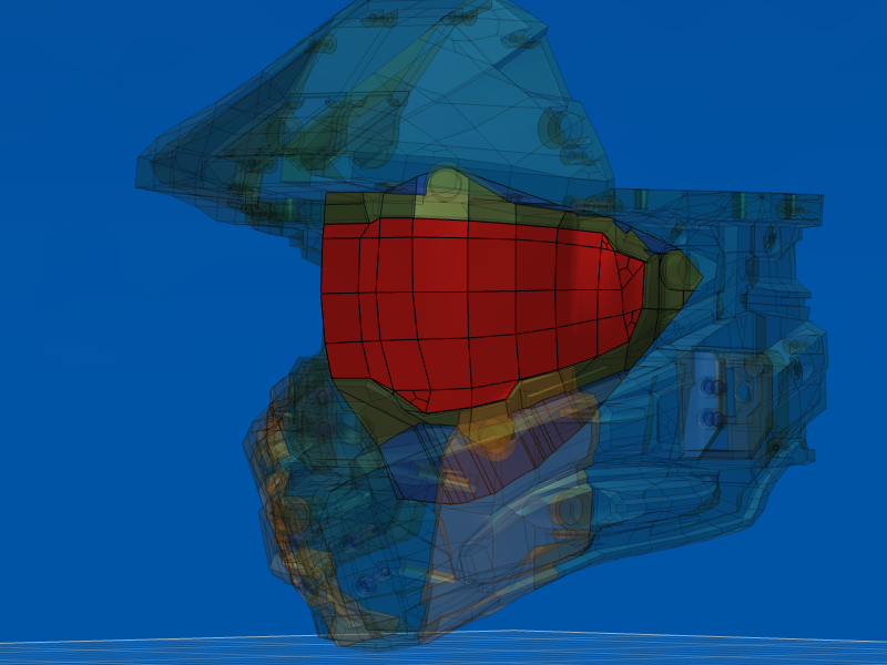
 spray it some more
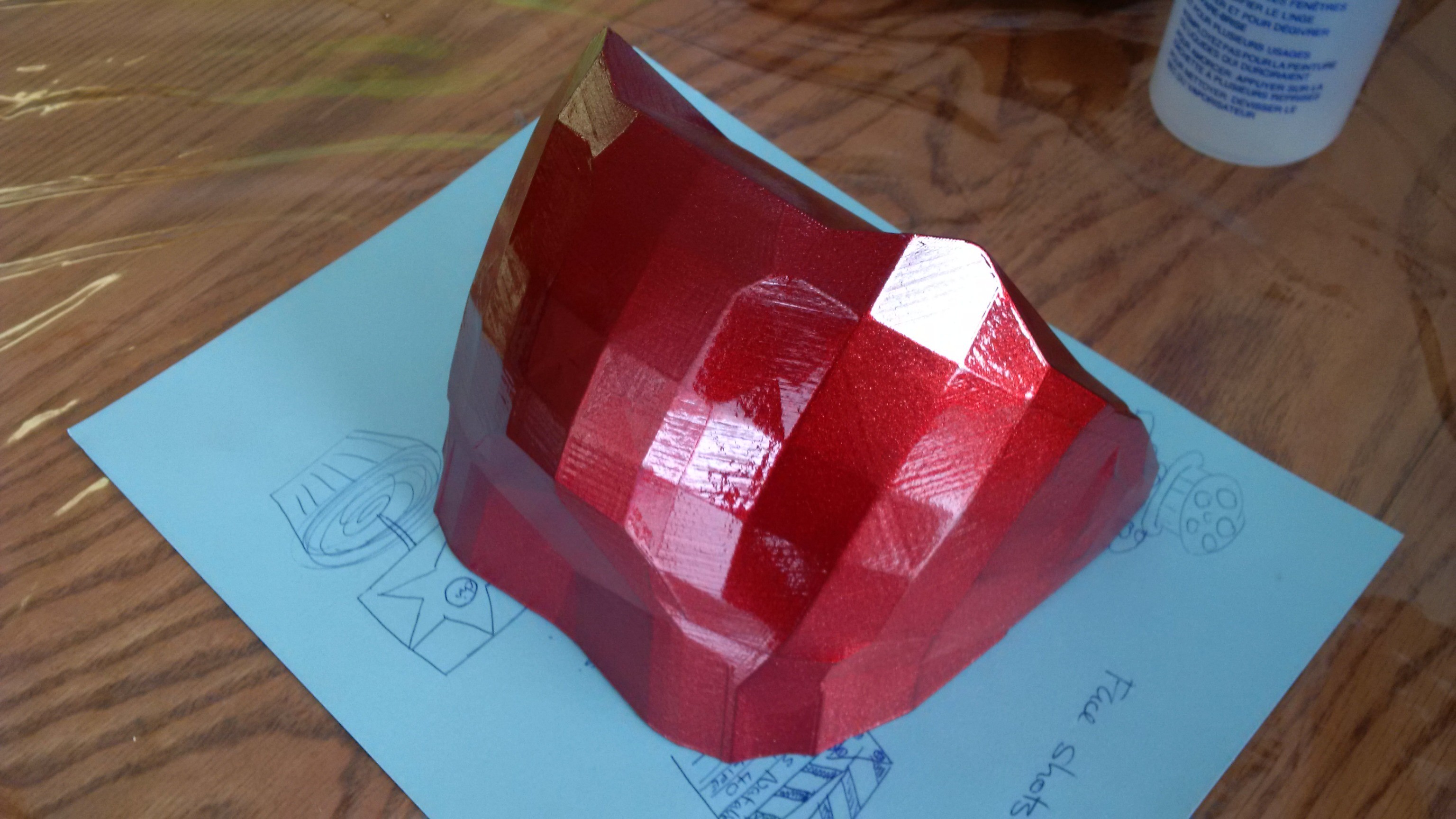
 But first of course heat it on a quartz heater hot box that you can collapse for storage and transport
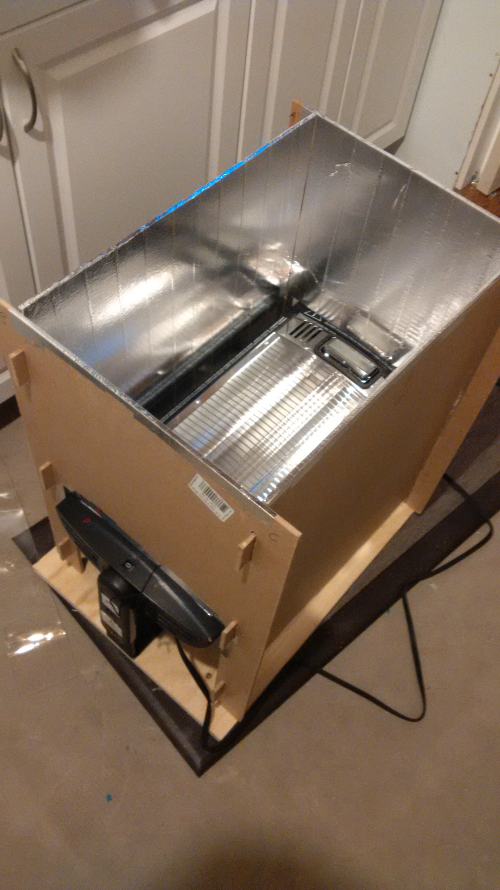 remove the molds with a bit of compressed air down the side
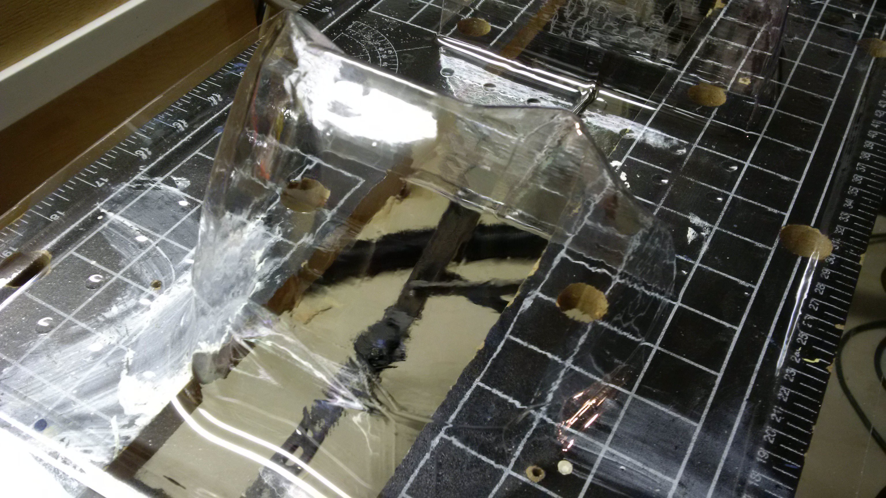 Cut out with metal shears, its just safer, easier and more accurate than a band saw. Add magnets and drop in place.
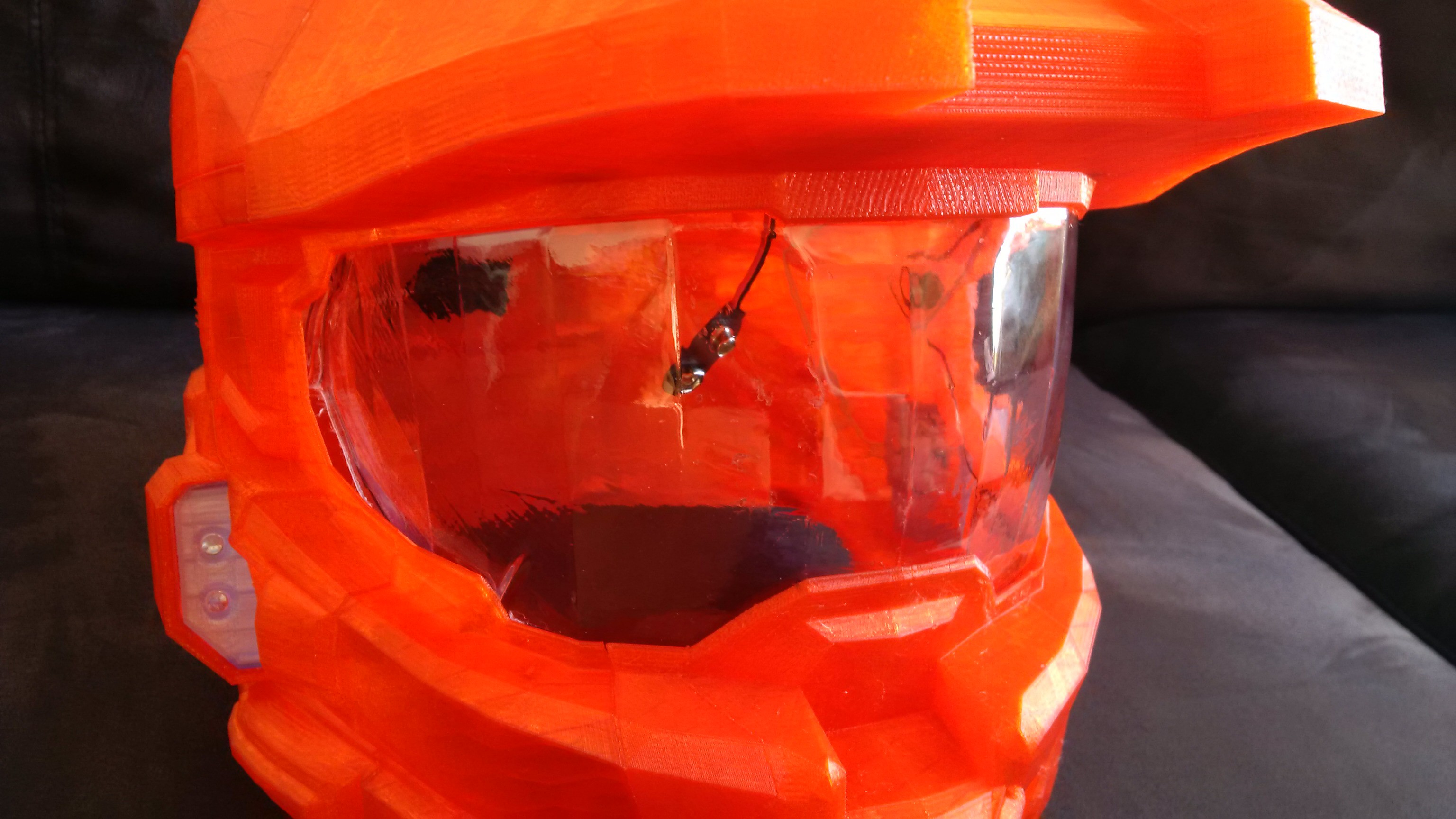 Next step is to paint the visor, but that's another adventure...