 Jeremy Gilbert
For many years now, I have been periodically scanning eBay of used airplane avionics, or aviation instrumentation. Once or twice a year I'll see something cheap enough (under $50) and fascinating enough that I'll buy. In the past I've restored or made operable all sorts of unusual little devices and learned a lot about the way complex instruments like this used to be designed.
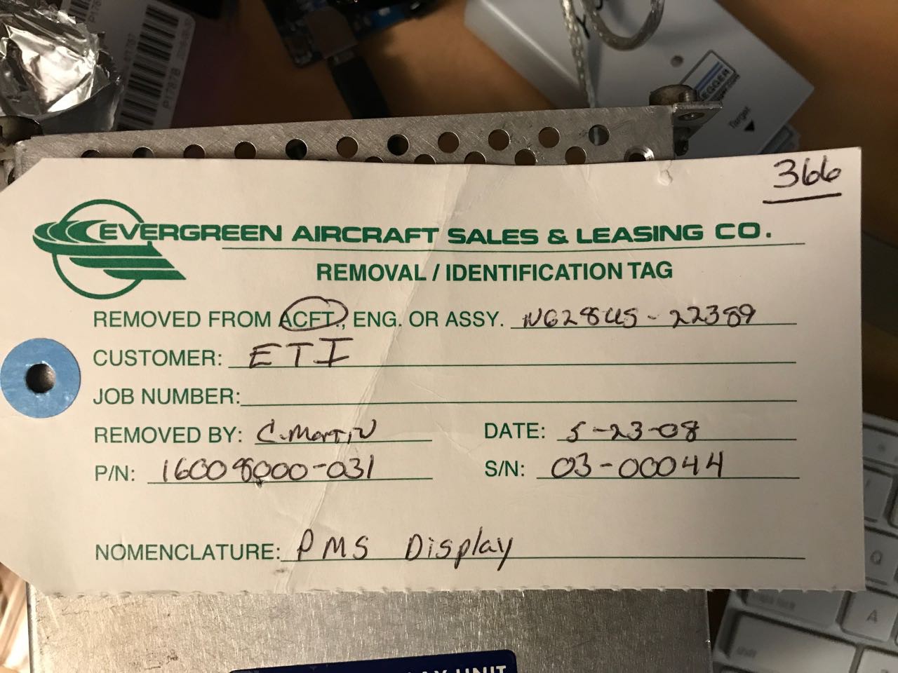
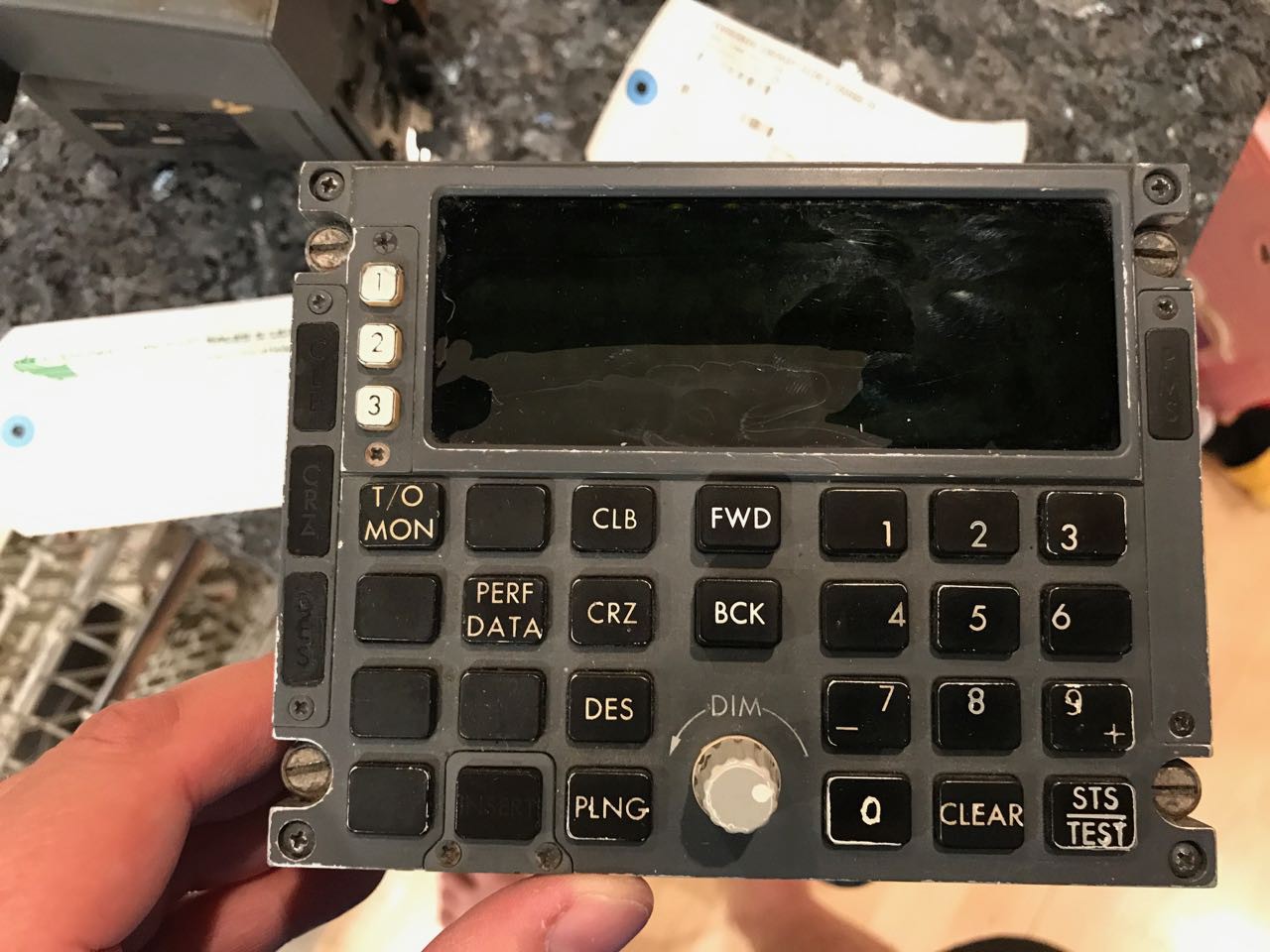
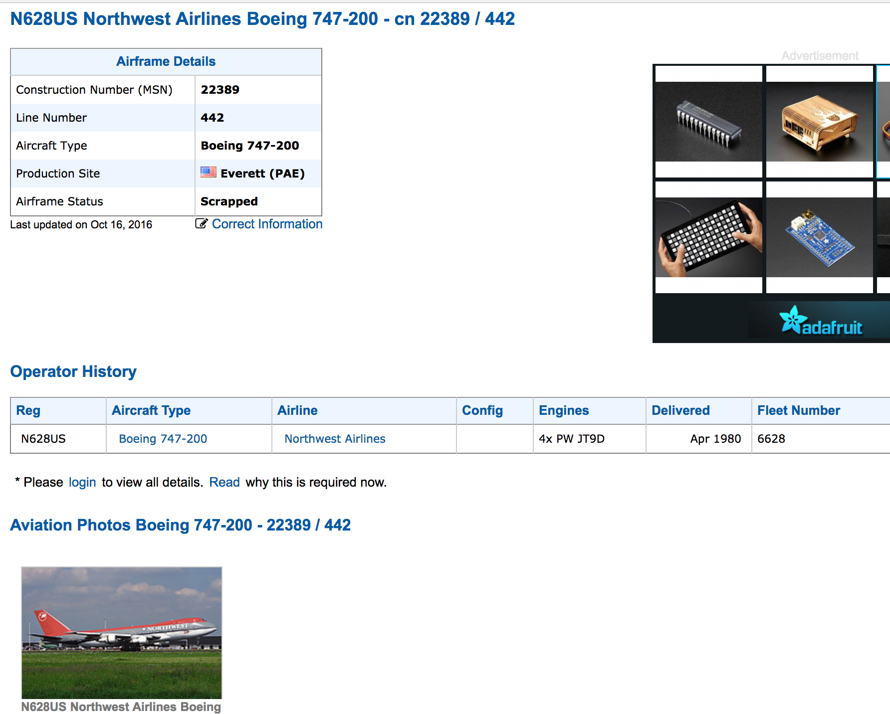
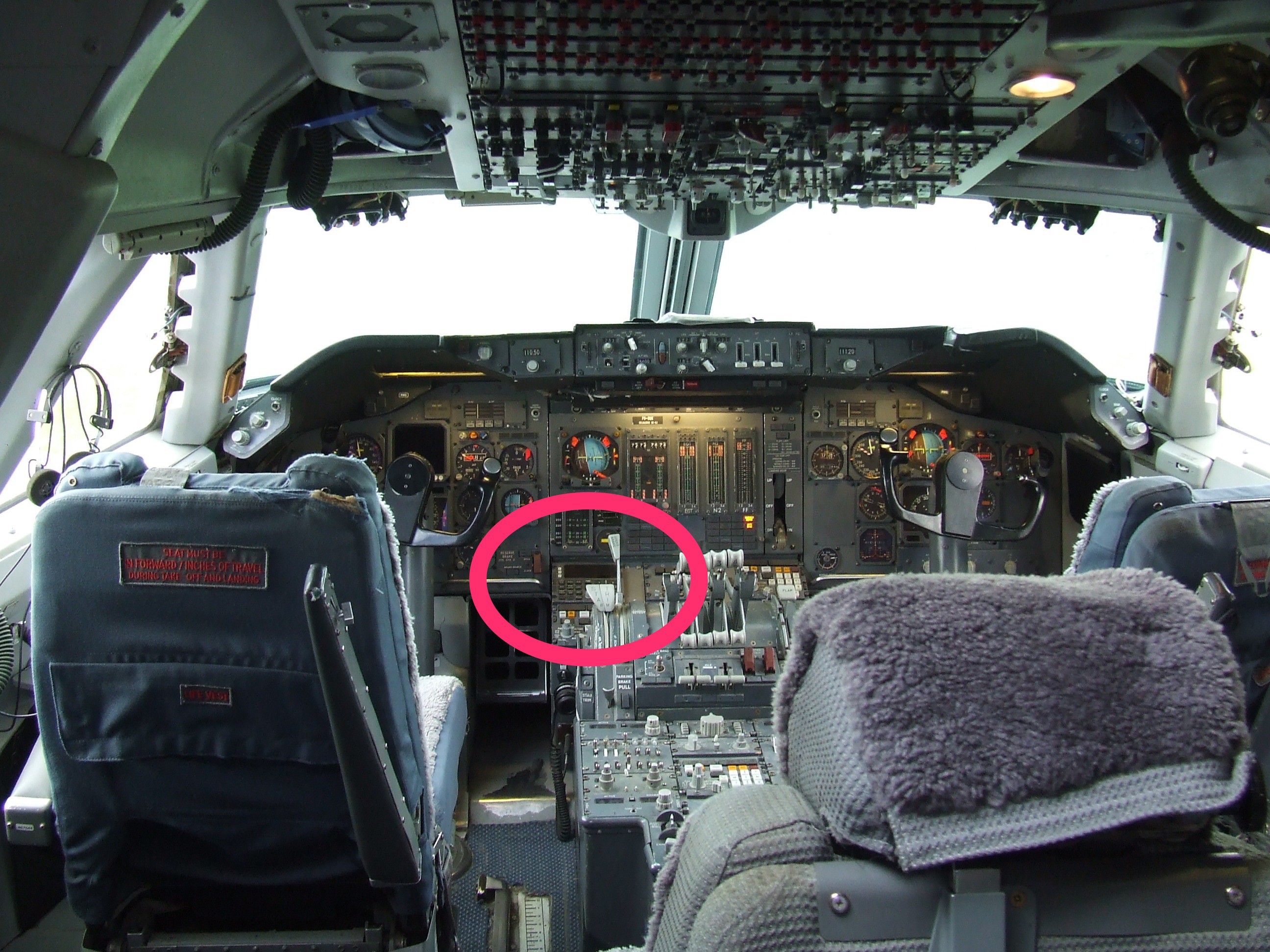
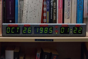
The 747-200 CDU is my most ambitious project to date. This device is basically an early computer, probably one of the only computers actually onboard an airplane when it was designed. It was a predecessor of the now-common flight management system, which is basically a overall control system tying together the autopilot, auto-throttle, position, altitude and course management systems together.
This CDU is basically a "head end" terminal to a complex computer that lived in the avionics bay of a 747. This computer itself is long-gone, but for my purposes it doesn't matter.
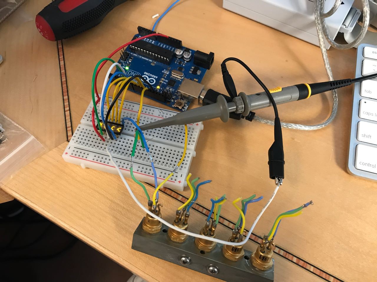
 For my full proof of concept, I decided to switch from using an Arduino to a Teensy 3.1. The Teensy is a 96Mhrz MCU board made by PJRC. It has far more RAM and speed than an Arduino and has been one of my goto components for my projects because of its excellent library and technical support.
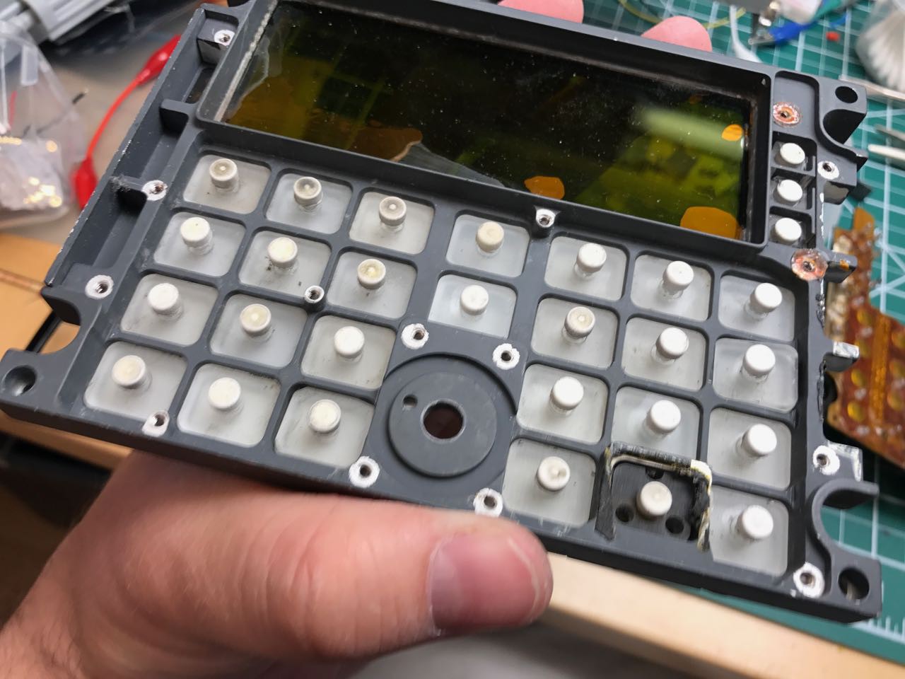
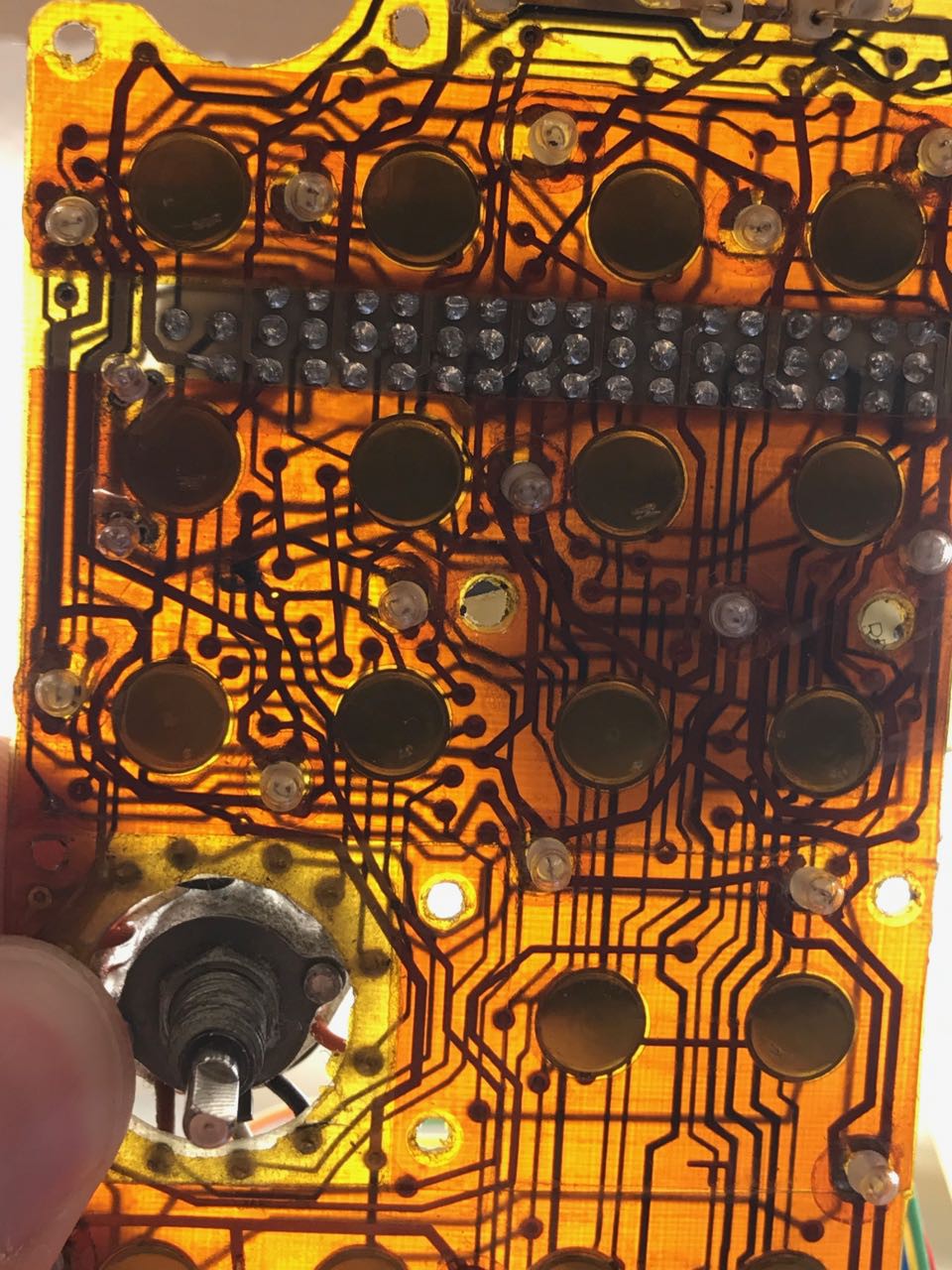
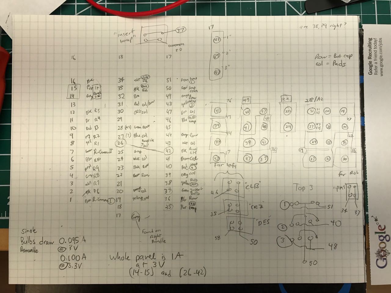
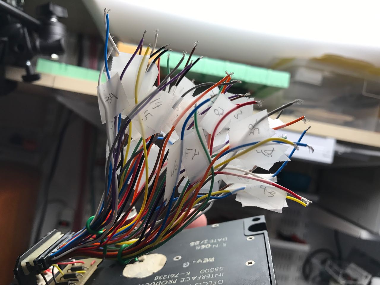
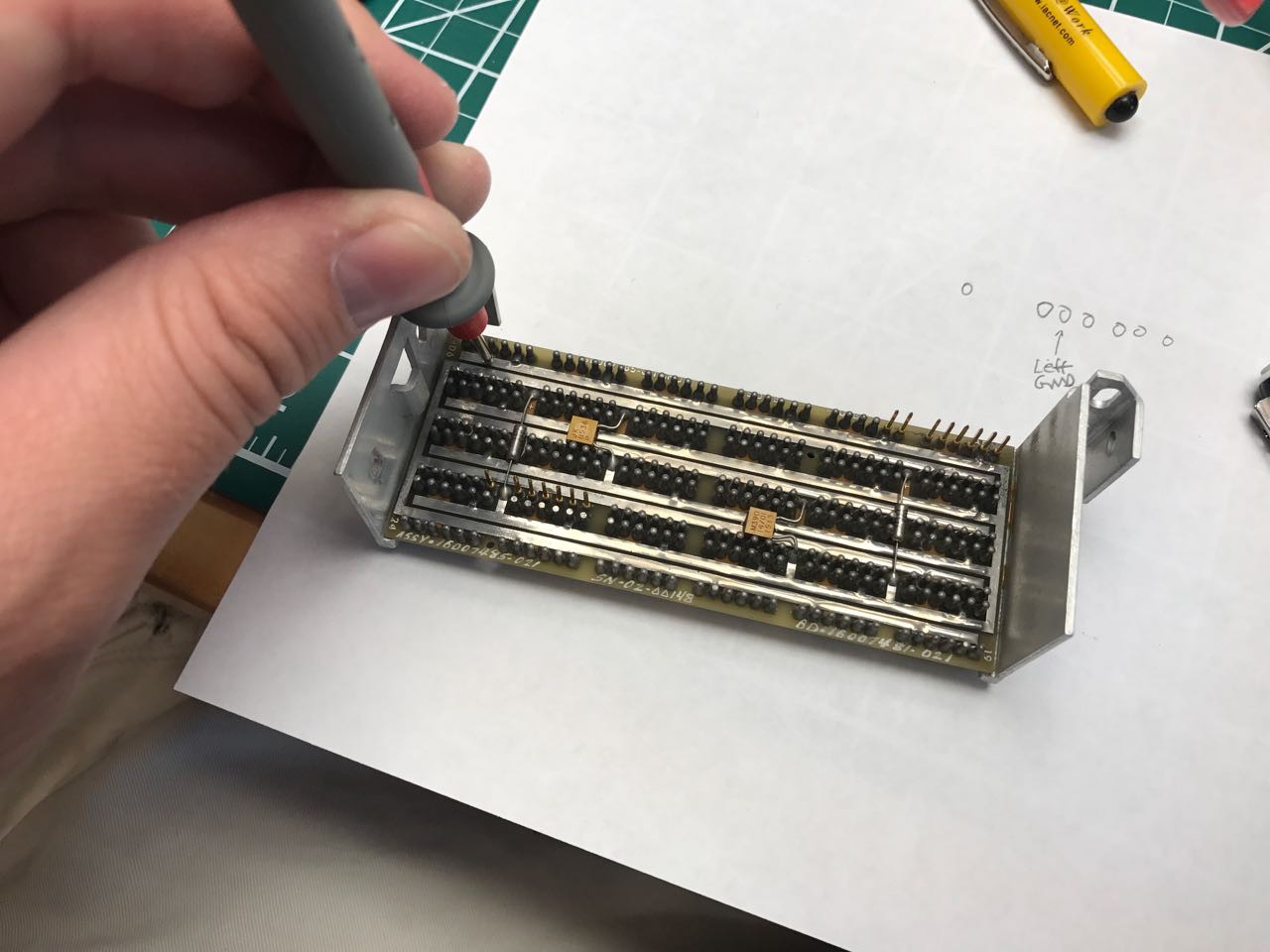
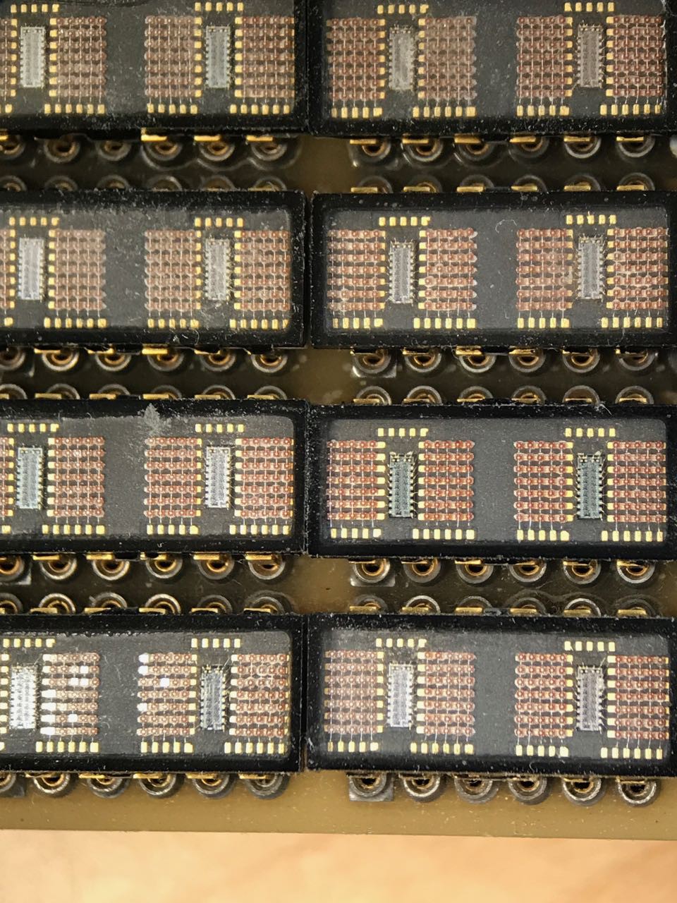
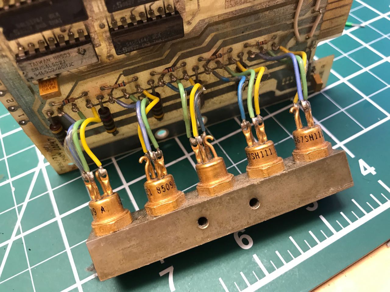
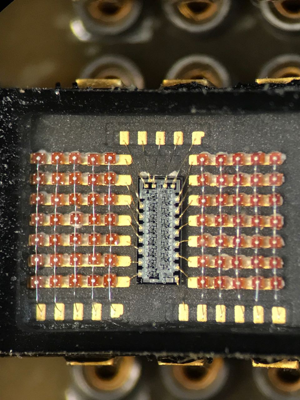 I started mapping out the pins and traces. Again, I was assuming that the pattern was feeing power and ground to each chip and that was the reason for the wide traces.


 Stephen Holdaway
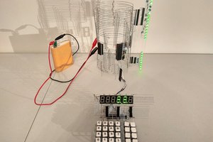
 matseng
 Leigh Oliver
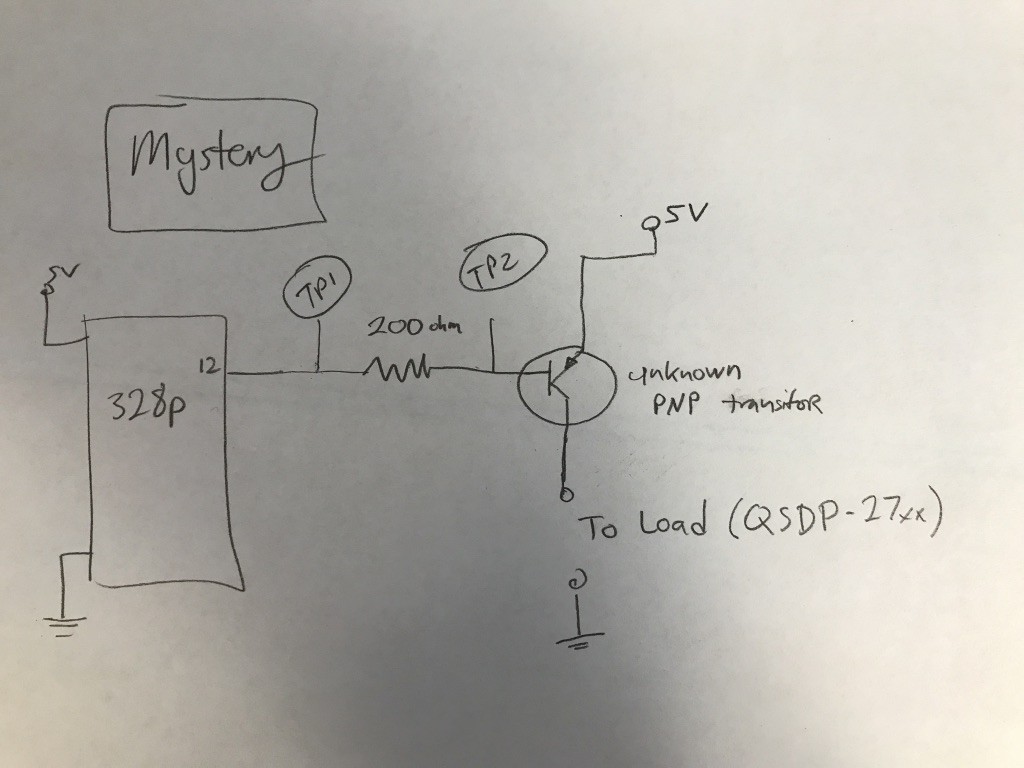
To answer your mystery about the transistor base voltage, think of the base - emitter junction as acting like a diode (thats how you tested it with a multimeter) as the current drawn from the base increases (microcontroller output 0v, sinking the current) the base voltage will decrease by one diode drop from the supply voltage (around 0.6v) and the remainder appears across the base resistor to limit the current. Thats why you don't see much change, as you explained it's the current doing the work.
Nice looking project!