 Katherina Baranova
Overview
Check out our demo video here:
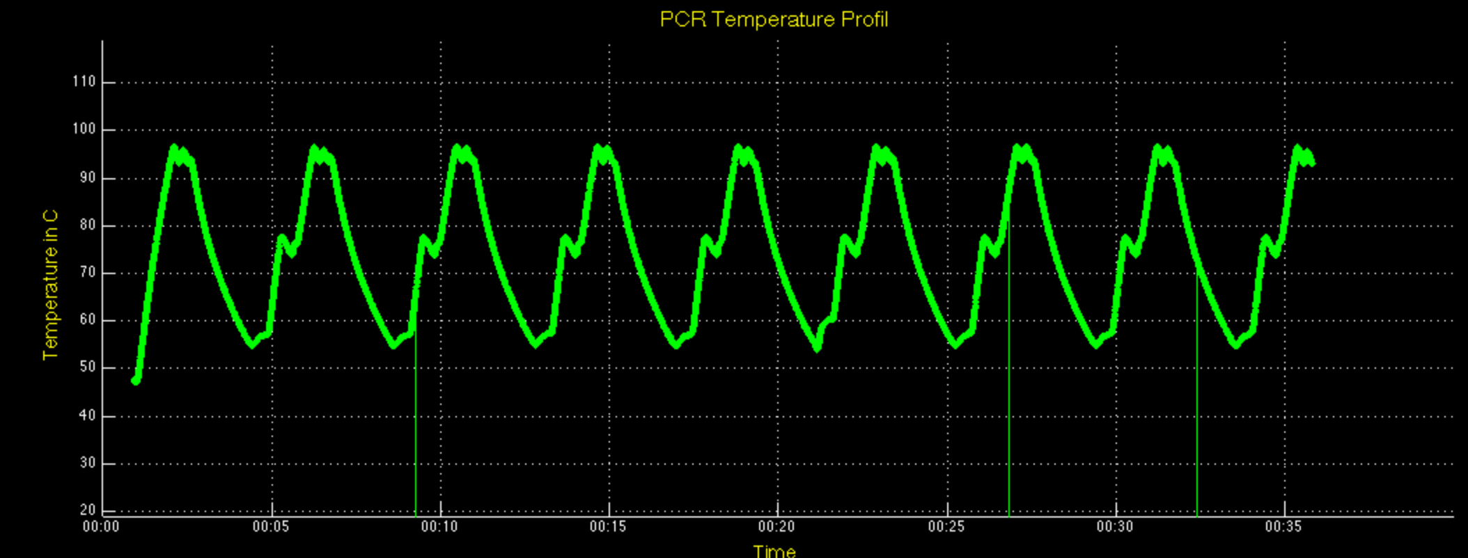
The thermal cycler is set to cycle to three different temperatures and holds for 15 seconds. The temperatures and hold times can be adjusted in the code. Below you will find the temperature profile of the thermal cycler as done in Matlab.
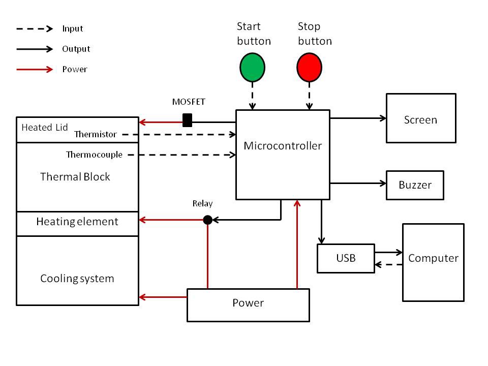
The microcontroller (Atmega 32U4) receives temperature data from a thermistor within the heated lid and from a thermocouple within the thermal block itself. The microcontroller uses this temperature data to regulate the temperature of the heated lid and to cycle the thermal block temperature to the desired levels. Once the thermal block reaches the specified temperature, it holds at a defined interval. The temperature and hold interval can only be specified in the code right now, but we're working on being able to input that information directly from an encoder. The microcontroller switches the Peltier from heating to cooling or back again via relays once the block finishes its hold, thus cycling the temperatures back and forth.
The microcontroller also outputs information to the screen. The screen displays information such as run time, number of cycles completed, temperature, and stage in current cycle. There are two buttons: one to start the cycler and a controlled stop. The cycler stops itself when it finishes a user defined number of cycles.
Below you will find the systems design document.
Breakdown of components
Power
The thermal cycler is powered by a 15V 10A modular power supply. The power runs to two relays which are switched back and forth, depending on whether the Peltier is to be heating or cooling at the time. The power supply also powers the fan and circuit board.
Rather than the one we used, we recommend a power supply more like this one:
http://www.unitedsale.com/Toshiba-1A187WI-2-AC-Adapter-15V-10A-150W-Power-Supply_p_1100.html
It is much safer and the project will be updated as time goes on with this power supply.
Heated Lid
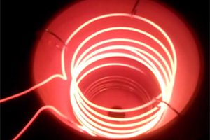
The heated lid uses nichrome wire to generate heat through resistance. The temperature is monitored through a thermistor embedded within the heated lid. The microcontroller receives temperature data from the thermistor and can adjust the voltage flowing to the heated lid through a mosfet, thus regulating the heat generated by the nichrome wire.
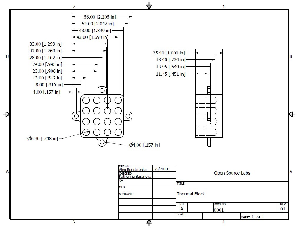
Thermal Block

The thermal block in our design is made of copper but one can substitute any metal with high thermal conductivity. The current design ca be improved by reducing the amount of material between the bottom of the wells and the heating element. We intend to modify the design in the future.
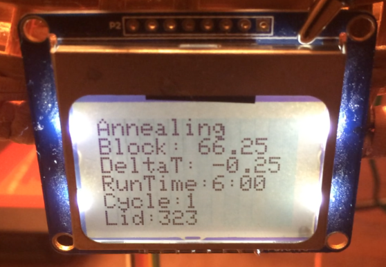
The Screen
The screen is a Nokia 5110/3310 monochrome LCD from Adafruit. The tutorial for setting up the screen can be found here, courtesy of Adafruit: https://learn.adafruit.com/nokia-5110-3310-monochrome-lcd
A picture of the screen in action is below:
The Software
The source code can be found here: https://github.com/opensourcelabsdotca/PCR
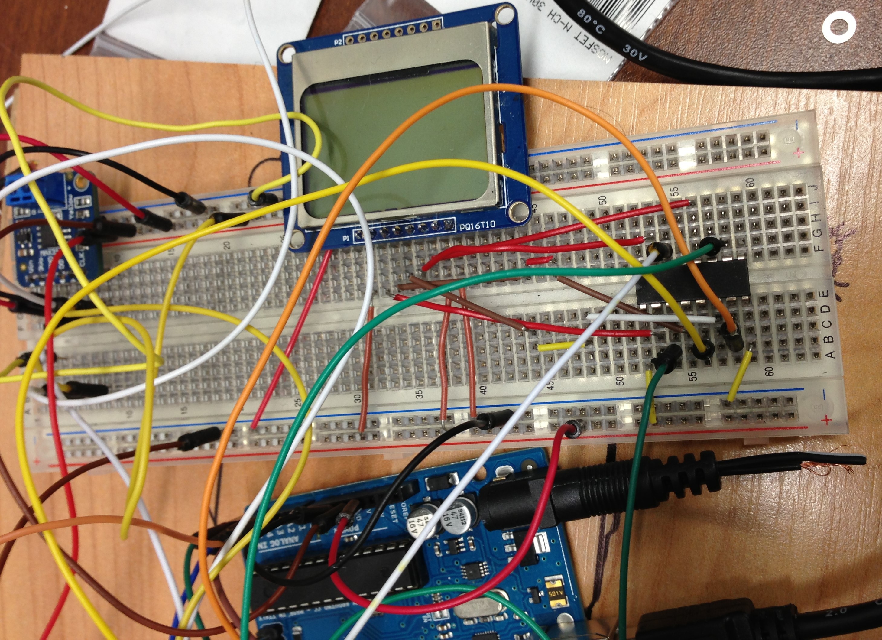
Everything was prototyped using an Arduino Uno and a breadboard before being adapted to a PCB controlled by an Atmega 32U4.
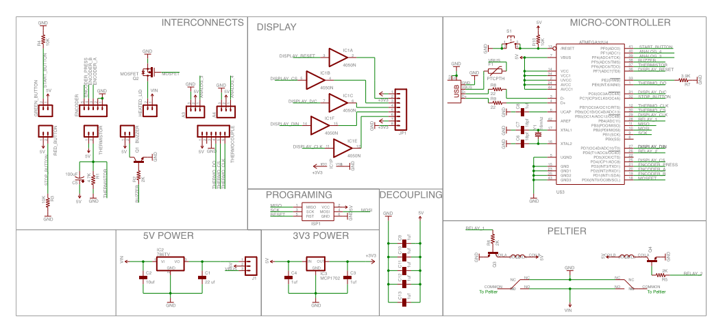
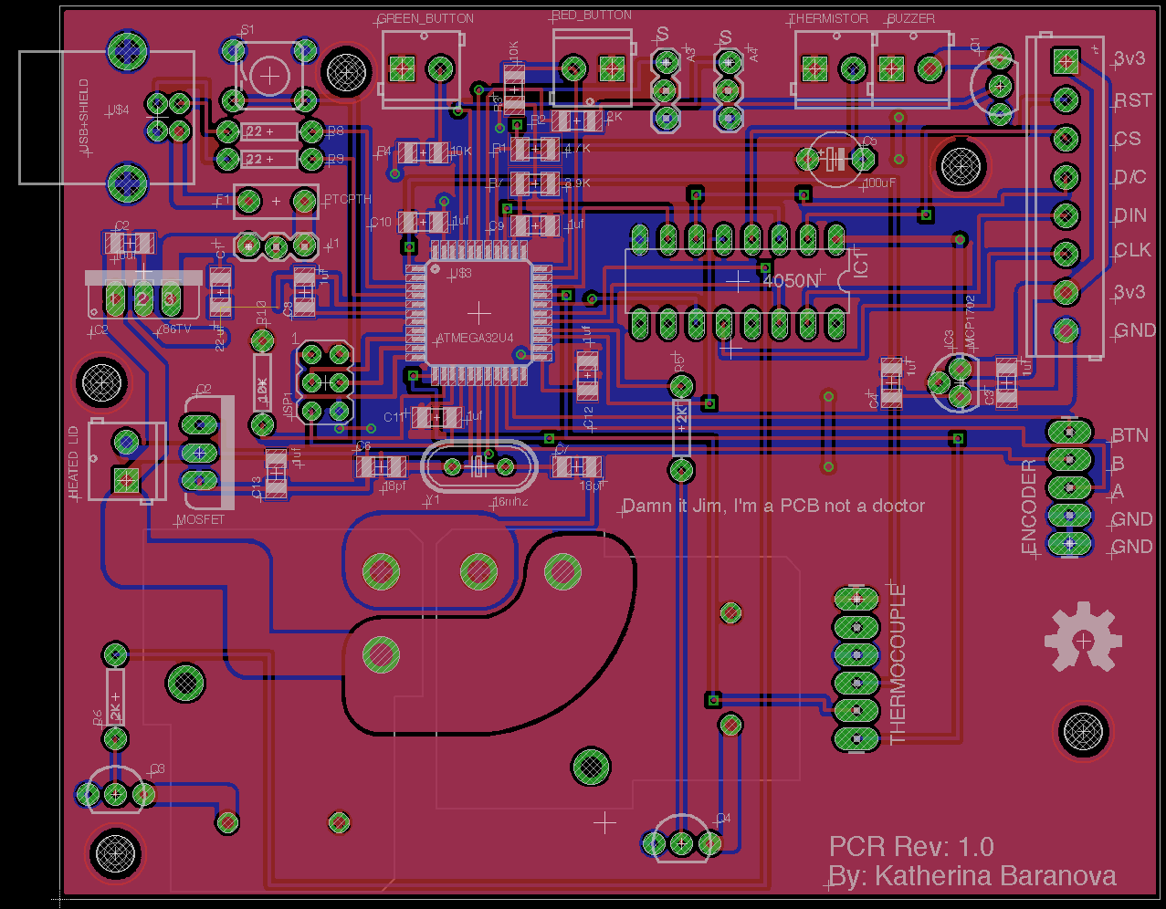
The PCB
The schematic for the circuit board can be found here:
https://www.dropbox.com/sh/gi5cror21jhg31e/AABSWjdxS45kbxXIKgTCvaMYa
We did all the work in Eagle CAD and sent the board to Itead Studios to be developed. The parts list for the circuit board can be found in the zipped folder in the Dropbox.


 Storken
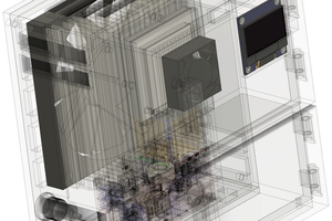
 Jung Hoon Lee
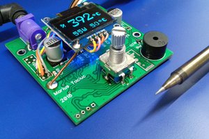
 Marius Taciuc
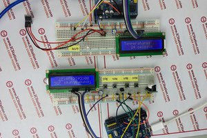
 icstation
I wanted to know K type thermocoupler is preferred than the other ones.