Katherina Baranova
-
Made PCB
08/19/2014 at 01:22 • 0 commentsNow that we had all the components on the breadboard, we created the PCB layout in Eagle. The circuit schematics for the breadboard can be found in the link to the Dropbox folder below. The files are meant to be viewed in Eagle.
https://www.dropbox.com/sh/gi5cror21jhg31e/AABSWjdxS45kbxXIKgTCvaMYa
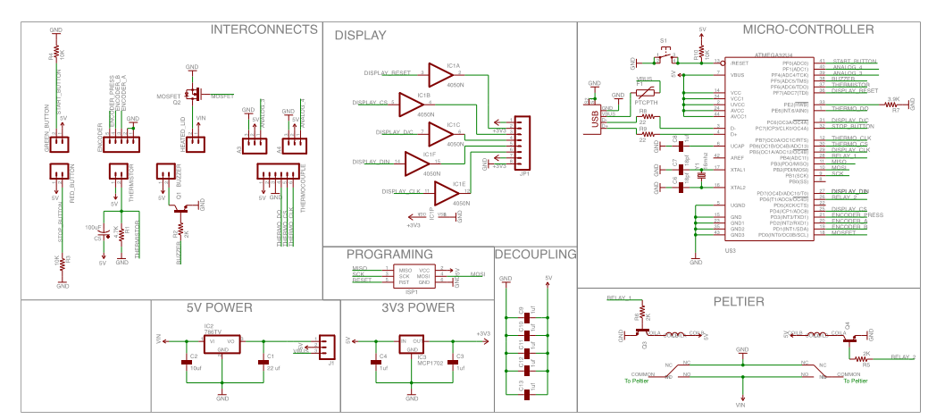
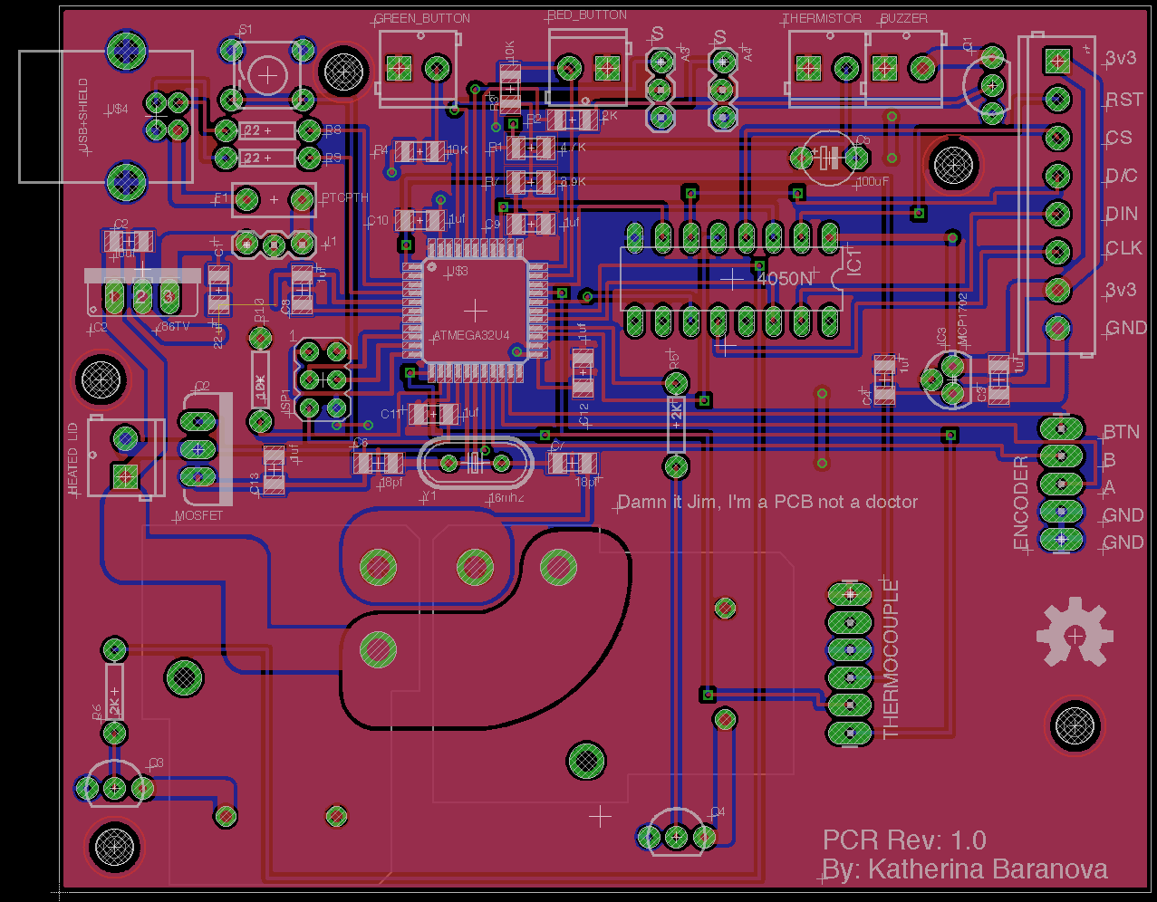
The schematic for the parts is shown below, as well as a screen shot of the PCB in Eagle.
![]()
![]()
We added an encoder in the circuit which we intend to use to allow the user to set the temperature and scroll through options but have not written it into the code as of yet.
We then sent the circuit diagram to Itead studio:
http://imall.iteadstudio.com/open-pcb/pcb-prototyping.html
They sent us the finished board. We soldered on all the components, programmed the Atmega using our previous code and the Arduino IDE. These tutorials explain how to do it nicely:
http://arduino.cc/en/Tutorial/ArduinoToBreadboard
http://arduino.cc/en/Main/Standalone
We then connected everything to the PCR and we now have a working prototype. The next step will be to design and build a case. We also intend to make an interactive screen with options for temperatures and holding times, as well as an option for saving frequently used programs. We intend to improve this project as time goes on so we have a great thermal cycler!
-
Created heated lid, buttons, and set up cycling
08/19/2014 at 01:16 • 0 commentsWe wrote in the code for the cycling, buttons, and heated lid at this stage. We used a switch case to define the three cases for our cycler: heating to temperature 1, cooling to temperature 2, and then heating to temperature 3. We used 95 degrees C, 55 degrees C, and 75 degrees C for our temperatures.
At this stage, the thermal block did not hold or stop after a predetermined number of cycles. It just went to our defined temperatures. It displayed the temperature on the screen but nothing else.
We set up the heated lid and buttons now as well. We looped Nichrome wire through a bread board and wrapped it in heat resistant tape. We set up the thermistor using this tutorial: https://learn.adafruit.com/thermistor/using-a-thermistor
And this temperature table: http://reprap.org/wiki/Thermistor
We set up the buttons using this tutorial: http://www.ladyada.net/learn/arduino/lesson5.html
We also set up a buzzer at this time that would alert us if the temperature went above 100, for debugging purposes.
-
Set Up Various Breadboard Components
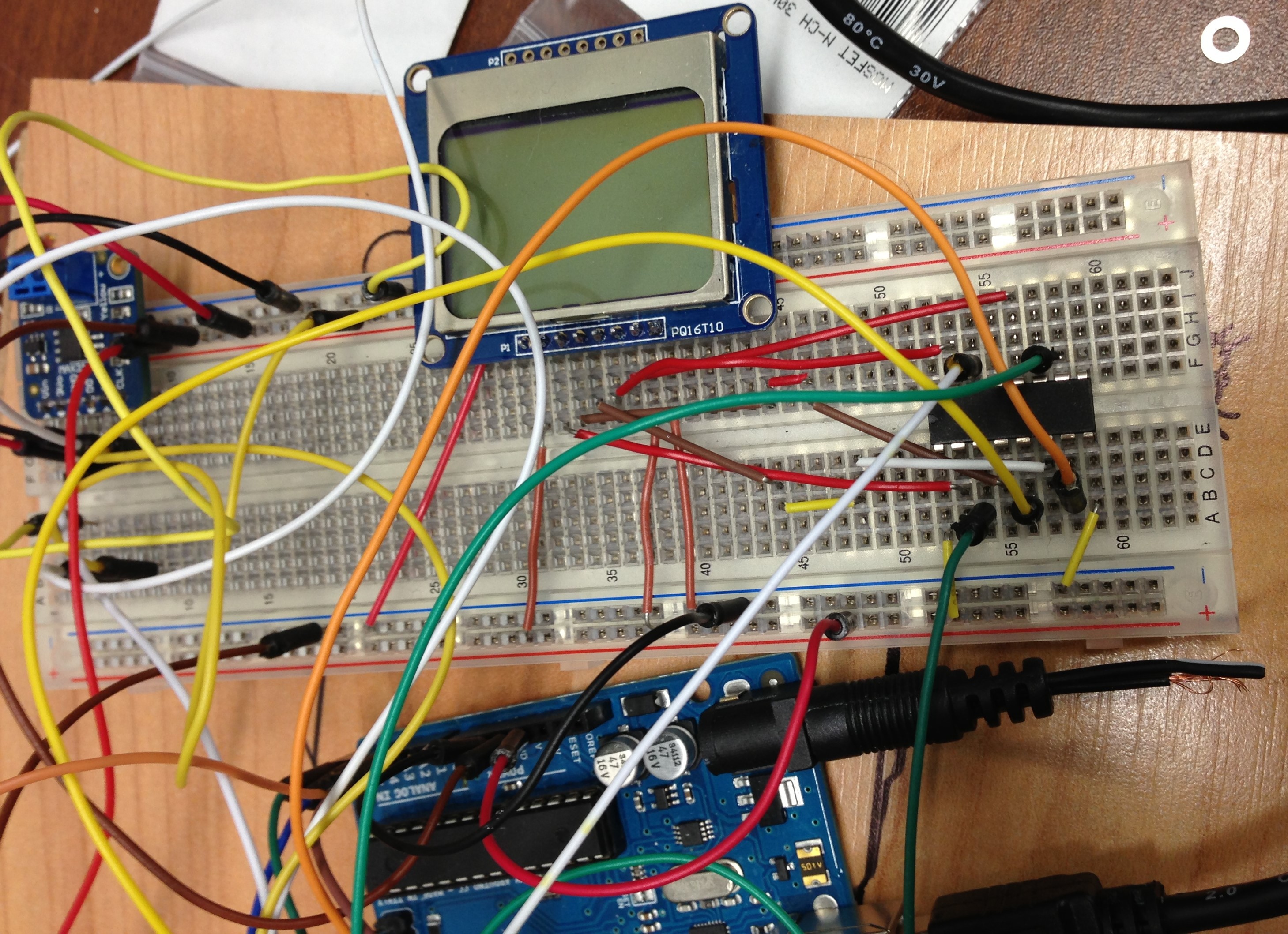
08/19/2014 at 01:15 • 0 commentsFor prototyping, we set up the various electrical components of our PCR on a breadboard controlled by an Arduino Uno.
![]()
We set up the thermocouple and screen using the tutorial provided here: https://learn.adafruit.com/thermocouple for the thermocouple and here https://learn.adafruit.com/nokia-5110-3310-monochrome-lcd for the screen.
We also set up the power supply, relays, and fan. The power supply is connected to the relays to control the peltier. It is also connected to the fan to power it. The relays are controlled by the arduino in response to the block temperature. We set up the relays to switch the peltier from heating to cooling at defined intervals, not through temperature sensing at this time, just to test if it works.
-
Cut Thermal Block
08/19/2014 at 01:13 • 0 commentsAbout two years ago we began this project with a lone thermal block.
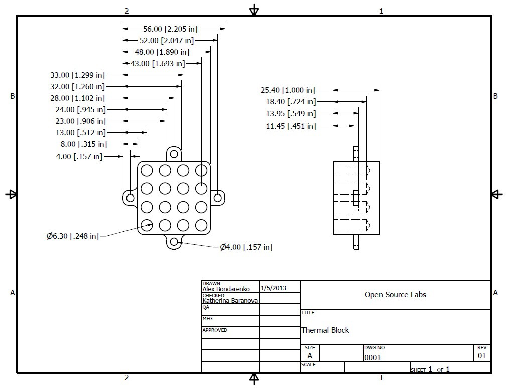
Our thermal block was generously donated by the physics machine shop at the University of Western Ontario. They donated the copper, and manufactured our thermal block to our specifications. We provided them with an autocad drawing, shown below:
![]()
The first design proved to be inefficient, with an overly large bottom. In the future, we intend to modify the block design to reduce thermal mass.
Open Source Thermal Cycler
A thermal cycler currently being developed for use as a Polymerase Chain Reaction (PCR) machine