-
1Step 1
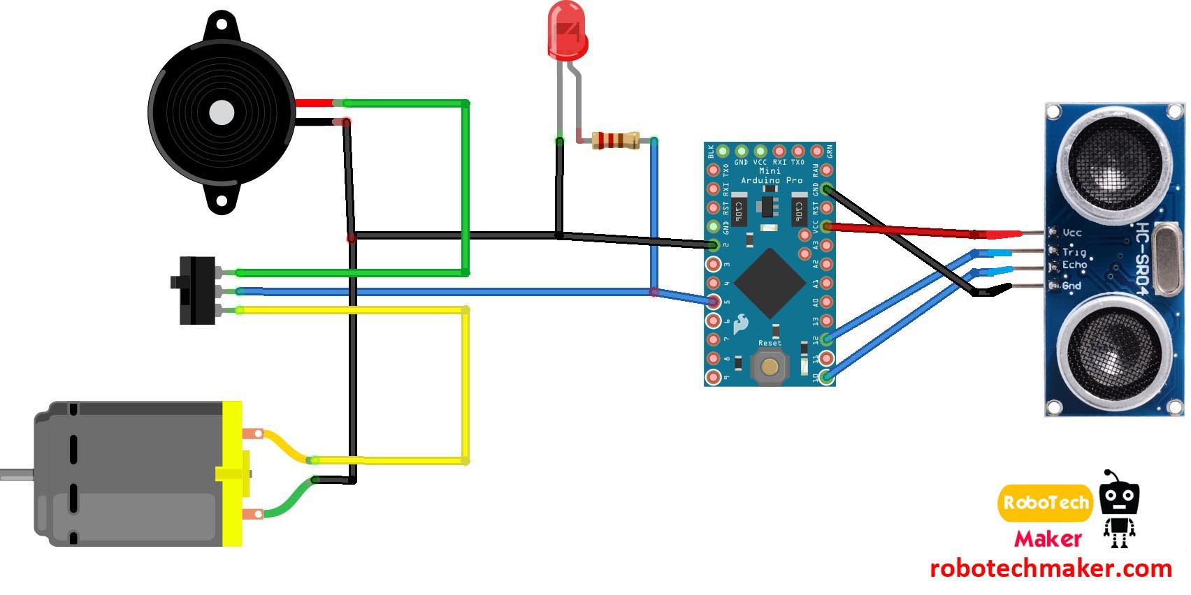
Circuit Diagram - Descriptions.
![]()
![]()
Wiring instruction.
Ground of LED, buzzer and vibration motor to GND of arduino
+ve of LED and middle leg of switch to Arduino pin 5
+ve of Buzzer to first leg of switch
+ve of Vibration motor to third leg of switch
Ultrasonic sensor
Ultrasonic sensor pin VCC - Arduino pin VCC
Ultrasonic sensor pin GND - Arduino pin GND
Ultrasonic sensor pin Trig - Arduino pin 12
Ultrasonic sensor pin Echo - Arduino PIN 12
The switch used here is for selecting the mode. ( buzzer or vibration mode.)
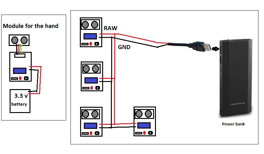
Figure 2 - Powering the modules - Connect the 4 arduino pro mini to a USB male pin and connect to a power bank. For the module in the hand use a small lithium battery.
-
2Step 2
Making the Modules
![]()
![]()
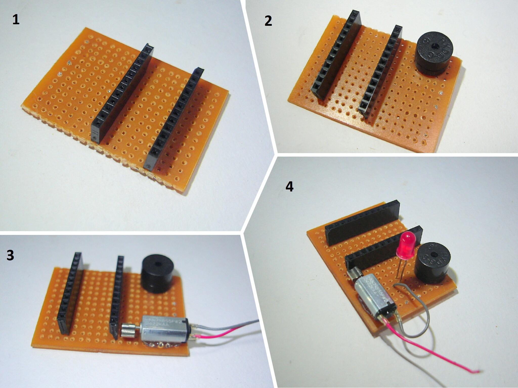
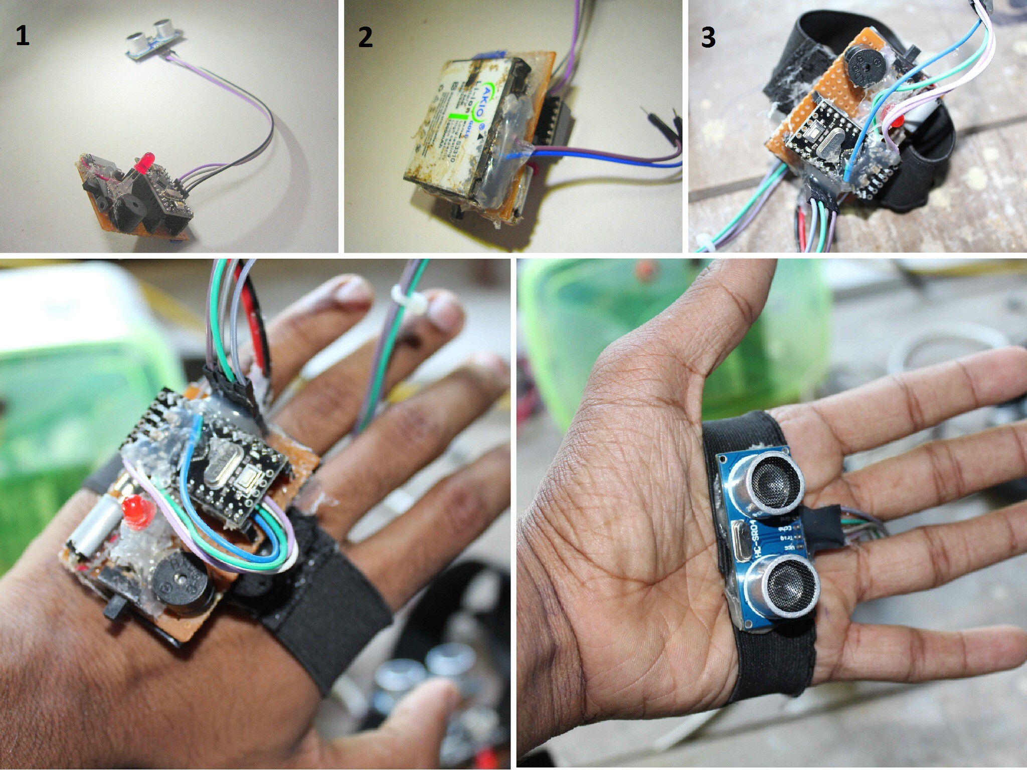
- First cut the pref board in 5 X 3 cm dimension and solder the female headers for the arduino to the board.
- Then solder the buzzer.
- Then connect the vibrating motor using the glue gun and solder wires to it.
- Then connect the LED.
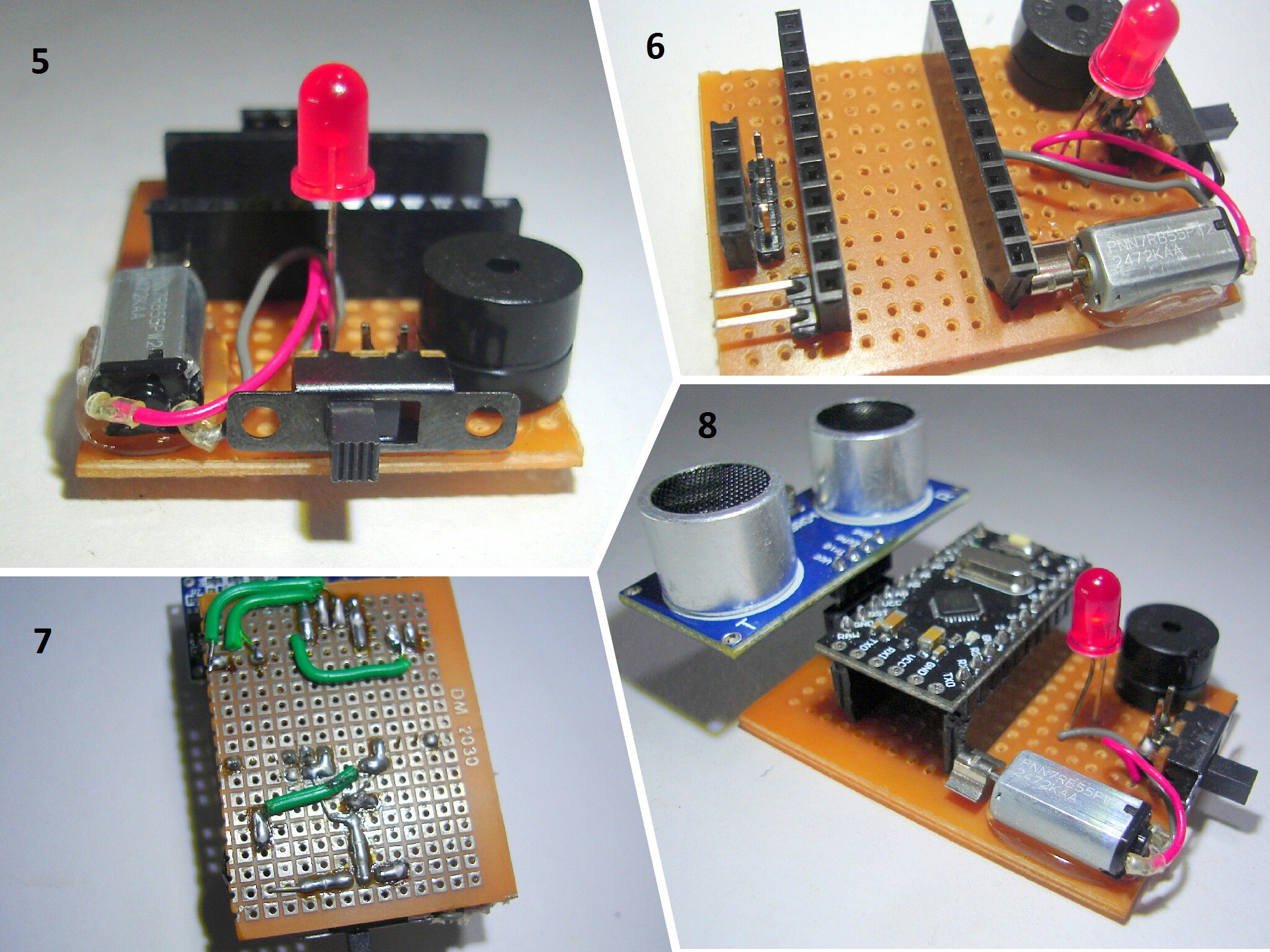
- Then connect the switch.
- Then connect header pins for ultrasonic sensors and for battery input.
- Then solder everything as shown in the circuit diagram.
- Now connect the arduino and ultrasonic sensor to the board
Also connect the elastic band to all the modules.
3 more modules are to be made in the same way us described above, but for the one in the hand, there is a little difference. visit the next step before making that last module
-
3Step 3
Code + Making the Module for the Hand
![]()
- Connect the ultrasonic sensor to the board by using 4 jumper cables.
- Then connect a 3.7 volt mobile battery to this module.
- Then connect the elastic band as shown in the figure.
At last upload the code to each arduino board and power the 4 other modules using a power bank.
Code used in the arduino -
  //VISIT : www.robotechmaker.com

  const int pingTrigPin = 12; //Trigger connected to PIN 7
  const int pingEchoPin = 10; //Echo connected yo PIN 8
  int buz=5; //Buzzer to PIN 4
  void setup() {
  Serial.begin(9600);
  pinMode(buz, OUTPUT);
  }
  void loop()
  {
  long duration, cm;
  pinMode(pingTrigPin, OUTPUT);
  digitalWrite(pingTrigPin, LOW);
  delayMicroseconds(2);
  digitalWrite(pingTrigPin, HIGH);
  delayMicroseconds(5);
  digitalWrite(pingTrigPin, LOW);
  pinMode(pingEchoPin, INPUT);
  duration = pulseIn(pingEchoPin, HIGH);
  cm = microsecondsToCentimeters(duration);
  if(cm<=50 && cm>0)
  {
  int d= map(cm, 1, 100, 20, 2000);
  digitalWrite(buz, HIGH);
  delay(100);
  digitalWrite(buz, LOW);
  delay(d);
  }
  Serial.print(cm);
  Serial.print("cm");
  Serial.println();
  delay(100);
  }
  long microsecondsToCentimeters(long microseconds)
  {
  return microseconds / 29 / 2;
  }
Thank you!
 Muhammed Azhar
Discussions
Become a Hackaday.io Member
Create an account to leave a comment. Already have an account? Log In.
very diligent..can I ask..this project not have block diagram?..
Are you sure? yes | no