-
AnyHardKeyboard
10/19/2017 at 17:51 • 0 commentsThe guy from Tynemouth software created a lot of USB keyboards. He using Arduino however, and I like plain C better. Also, I cannot find his code right now. Because I don't think scanning & debouncing could be that hard, I made a start. This guy did however inspire me by showing that an ATmega microcontroller with V-USB is capable of being used as a keyboard.
My plan is to write a code generation tool, and today I started. It's only the init routine for now, but it's a start. :-) The code generation tool will justify the name AnyHardKeyboard; the plan is to be able to give a CSV of the keyboard layout to this little program, and have it generate the keyboard routines from it.
A big thanks to the guys of FreeBSD who put a text format key table online (everyone else points to the PDF). I'll use a modified version of that one for the key mapping.
What I have now is the following:
,"B5","B6","C0","C1","C2","C3","C4","C5"
"D0","ESCAPE","F12","`","Tab","Caps Lock","A",,1
"D1","F3","F2",2,"W","S","X","Z","Q"
"D3","Fn","LeftShift","LeftControl","Left GUI","RightShift","LeftAlt","RightAlt","RightControl"
"D4","F6",6,5,"R","G","F","V","T"
"D5","F5","F4",4,"ENTER","D","C3",,3
"D6","F7",8,7,"Y","H","N","B","U"
"B0","F9","F8","I","K","M",",","Spacebar","J"
"B1","F10",9,"O","L",";",".",,"P"
"B2","F11","F12",0,"[","'","/",,"-"
"C6","Scroll Lock","Pause","=",,,,,"]"
"B3","Delete","Insert","Backspace","ENTER","\","PageDown","DownArrow","RightArrow"
The topmost row and the leftmost column designate the ATmega8's pins used.
The proof-of-concept Python code:
import csv
with open('esprimo.csv', 'rb') as csvfile:
    csvreader = csv.reader(csvfile, delimiter=',', quotechar='"')
    i = 0
    inputmatrix = []
    writepins = []
    for row in csvreader:
        inputmatrix.append(row)
        if i > 0:
            writepins.append(row[0])
            #writepins[i] = row[1]
        i = i + 1
    readpins = inputmatrix[0][1:]
    writepins.sort()
    readpins.sort()
    outfile = "init_kb_pins() {\r\n"
    outfile = outfile + "\t" + '// write pins\r\n'
    buf = ''
    lastp = ''
    for p in writepins:
        if lastp != p[0] and lastp != '':
            outfile = outfile + "\t" + 'DDR' + lastp + ' |= ' + buf + "; // set the bits as input\r\n"
            outfile = outfile + "\t" + 'PORT' + lastp + ' &= ~('+ buf + "); // set voltage low in case bits are set as output while scanning\r\n";
            buf = ''
        if buf != '':
            buf = buf + ' |'
        buf = buf + ' (1 << '+p[1]+')'
        lastp = p[0]
    outfile = outfile + "\t" + 'DDR' + lastp + ' |= ' + buf + "; // set the bits as input\r\n"
    outfile = outfile + "\t" + 'PORT' + lastp + ' &= ~('+ buf + "); // set voltage low in case bits are set as output while scanning\r\n";
    buf = ''
    lastp = ''
    outfile = outfile + "\r\n\t// read pins\r\n"
    for p in readpins:
        if lastp != p[0] and lastp != '':
            outfile = outfile + "\t" + 'DDR' + lastp + ' |= ' + buf + "; // set the bits as input\r\n"
            outfile = outfile + "\t" + 'PORT' + lastp + ' |= '+ buf + "; // activate pull-ups\r\n";
            buf = ''
        lastp = p[0]
        if buf != '':
            buf = buf + ' |'
        buf = buf + ' (1 << '+p[1]+')'
    outfile = outfile + "\t" + 'DDR' + lastp + ' |= ' + buf + "; // set the bits as input\r\n"
    outfile = outfile + "\t" + 'PORT' + lastp + ' |= '+ buf + "; // activate pull-ups\r\n";
    outfile = outfile + "}\r\n\r\n"

    print outfile

    print writepins
    print readpins
which nicely generates:
init_kb_pins() {
        // write pins
        DDRB |=  (1 << 0) | (1 << 1) | (1 << 2) | (1 << 3); // set the bits as input
        PORTB &= ~( (1 << 0) | (1 << 1) | (1 << 2) | (1 << 3)); // set voltage low in case bits are set as output while scanning
        DDRC |=  (1 << 6); // set the bits as input
        PORTC &= ~( (1 << 6)); // set voltage low in case bits are set as output while scanning
        DDRD |=  (1 << 0) | (1 << 1) | (1 << 3) | (1 << 4) | (1 << 5) | (1 << 6); // set the bits as input
        PORTD &= ~( (1 << 0) | (1 << 1) | (1 << 3) | (1 << 4) | (1 << 5) | (1 << 6)); // set voltage low in case bits are set as output while scanning
        // read pins
        DDRB |=  (1 << 5) | (1 << 6); // set the bits as input
        PORTB |=  (1 << 5) | (1 << 6); // activate pull-ups
        DDRC |=  (1 << 0) | (1 << 1) | (1 << 2) | (1 << 3) | (1 << 4) | (1 << 5); // set the bits as input
        PORTC |=  (1 << 0) | (1 << 1) | (1 << 2) | (1 << 3) | (1 << 4) | (1 << 5); // activate pull-ups
}
Please don't punish me for all the code duplication... I really miss IntelliJ's "extract method" and other refactoring functionality. Perhaps I should rewrite it in Java, or try IDLE...
I also still have to find out if I used the correct bit fiddling operators, but I think I have it right.
-
Connecting the wires & testing the software
10/16/2017 at 19:17 • 0 commentsConnecting the wires
I was very happy that with combining the modifier key lines, I get to 19 distinct wires needed. Exactly the amount of wires I have left on my microcontroller. Phew...
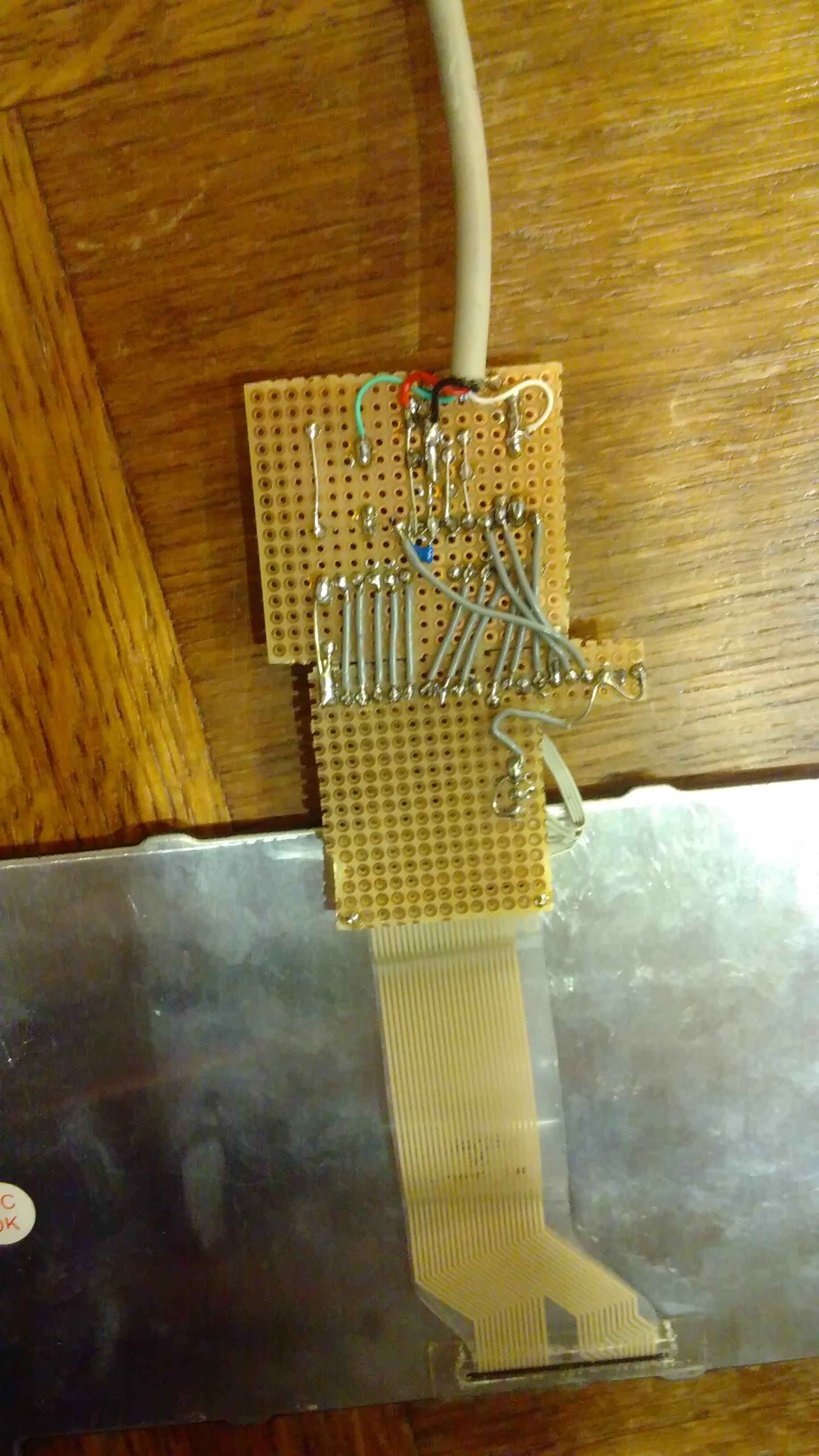
Most of the soldering is now finished:
![]()
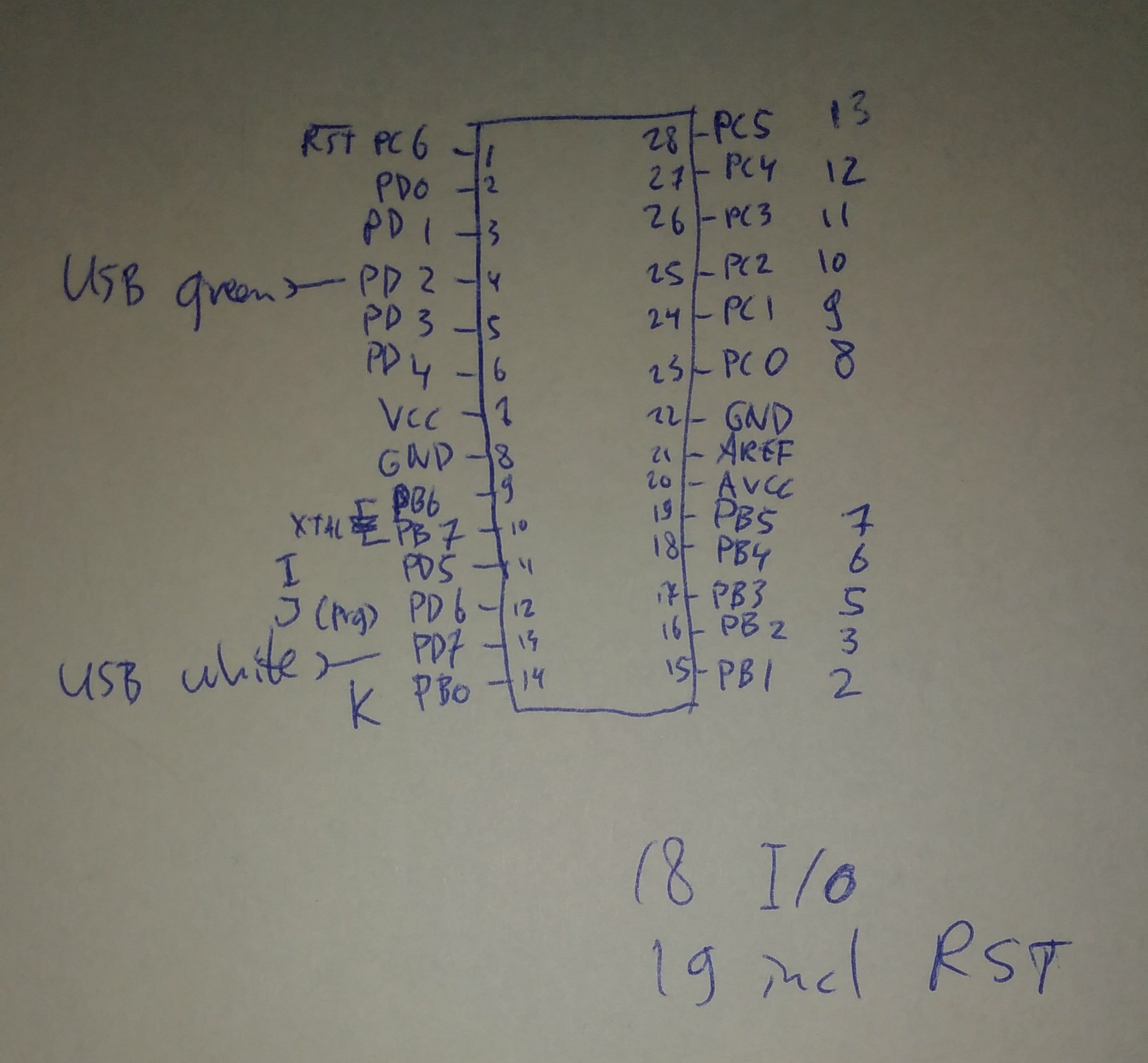
which yields the following schematic:
![]()
The RST is reserved for wire number '4', because that's the least interesting wire from the keyboard. When I find out how to configure the ATmega8 to use it as PC6 I can use that once. PD0..PD4 also still need to be connected.
Software
I baptized the software project 'AnyHardKeyboard', or AnyHKBD, of course referring to the android's software counterpart that can do many keyboard layouts. More on the USB hardware is in the first log. There I mentioned that the basic software is working. In it's current state it reports itself as follows:
[84822.027766] usb 4-2: Product: AnyHKBD
[84822.027770] usb 4-2: Manufacturer: ronaldteune
[84822.037987] input: ronaldteune AnyHKBD as /devices/****/input/input178
[84822.098920] hid-generic *****: input,hidraw4: USB HID v1.01 Keyboard [ronaldteune AnyHKBD] on usb-0000:00:12.1-2/input0
Time for a small software test with the (almost) full hardware. I'll go for pulling wire K down and then checking PC1,2,5 which should give K, M, J. After one retry (I should really pull wire K down, else it doesn't work...) I have a keyboard that's working! Phew, the 180 ohms of the keyboard is enough to pull the uC inputs to low. It's really funny to have real letters appear on the screen from a real keyboard, with some strange handmade PCB in between... This letters I have typed with my new keyboard as a proof ;-) jkmjmkmjkmjjkmmj
The software can be found here: anyhardkeyboard.tar.gz. It needs cleaning up (it's based on the slideshow presenter) and it needs matrix scanning code together with the debouncing that's already in. I can make it up myself, but have found this line of projects as inspiration and for me to perhaps not make the same mistakes. It's Arduino-based however, so it'll need a little rewrite.
Final words
This makes the first big hurdle almost being taken. I allowed myself to start looking into the DVI-LVDS circuitry after finishing this one (to prevent myself from buying stuff that I'll never use because more complicated things need to be solved - like that time when I wanted to create my own open source Atmel based, non-arduino, OBD2 adapter...) I'm hoping a lot that my TFT is compatible with an off-the-shelf eBay adapter...
-
Feels like Sudoku
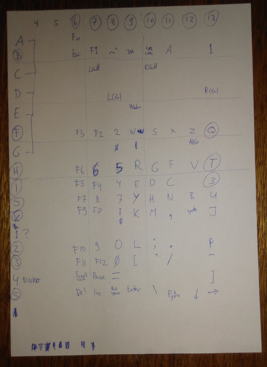
10/15/2017 at 12:23 • 0 commentsBased on the layout of the flex cable I guessed the rows and columns, giving letters to one, and numbers to the other. I guessed wrong. My measured values were enough basis for a more systematic approach, though about three lines (4-6) I was unsure whether they would be rows or columns.
It is time for 'solving the Sudoku'. Guessing what key could be in what location, and measuring the resistance for several combinations of wires. Rarely the first time right. Most of the time starting with pressing multiple keys at once, and then releasing group by group and one by one revealed a new key. QTP is not only the name of an automated test suite from HP, but also the last three letters that need to be found... After quite some testing, the P was found but the Q and T are still not, and neither is the 3 and the menu key. There might be a problem with the '1' line - but I think this is a good time to connect the microcontroller to scan a little more easily. Or should I first re-check the '1' connections again...
I think I have to choose what lines I like and what lines I don't need. And it looks like lines ACDEG can be conveniently combined into one - probably making it harder to detect Ctrl+Alt+Shift+F1 key combinations correctly, but making it possible in the first place to fit everything in the - oops - not so many uC lines I have available.
![]()
[edit]
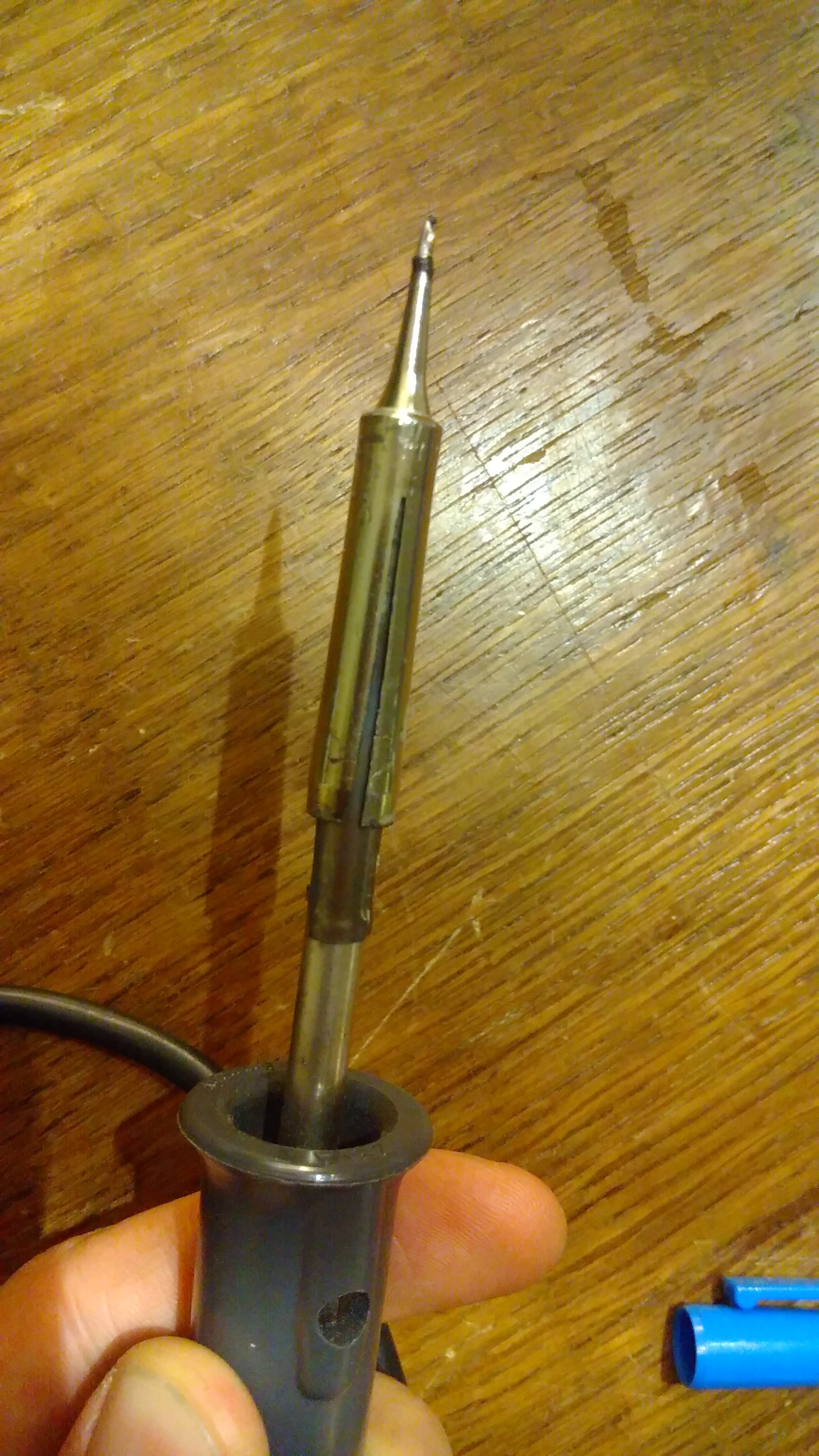
I forgot to tell something. In the last log, I said that one of the wires didn't seem to make contact anymore. I am quite happy with my ZEVA Arolsen something soldering iron, but the tip was a bit too large. Thankfully someone created a "907H-I" soldering tip, someone else measured it and put it on eBay, and I have a metal saw to adapt it for the final zero point something millimeters:![]()
Waiting for this to arrive is part of why it took so long for me to work on this project again. But with this new tip, I was able to repair all the little wires.
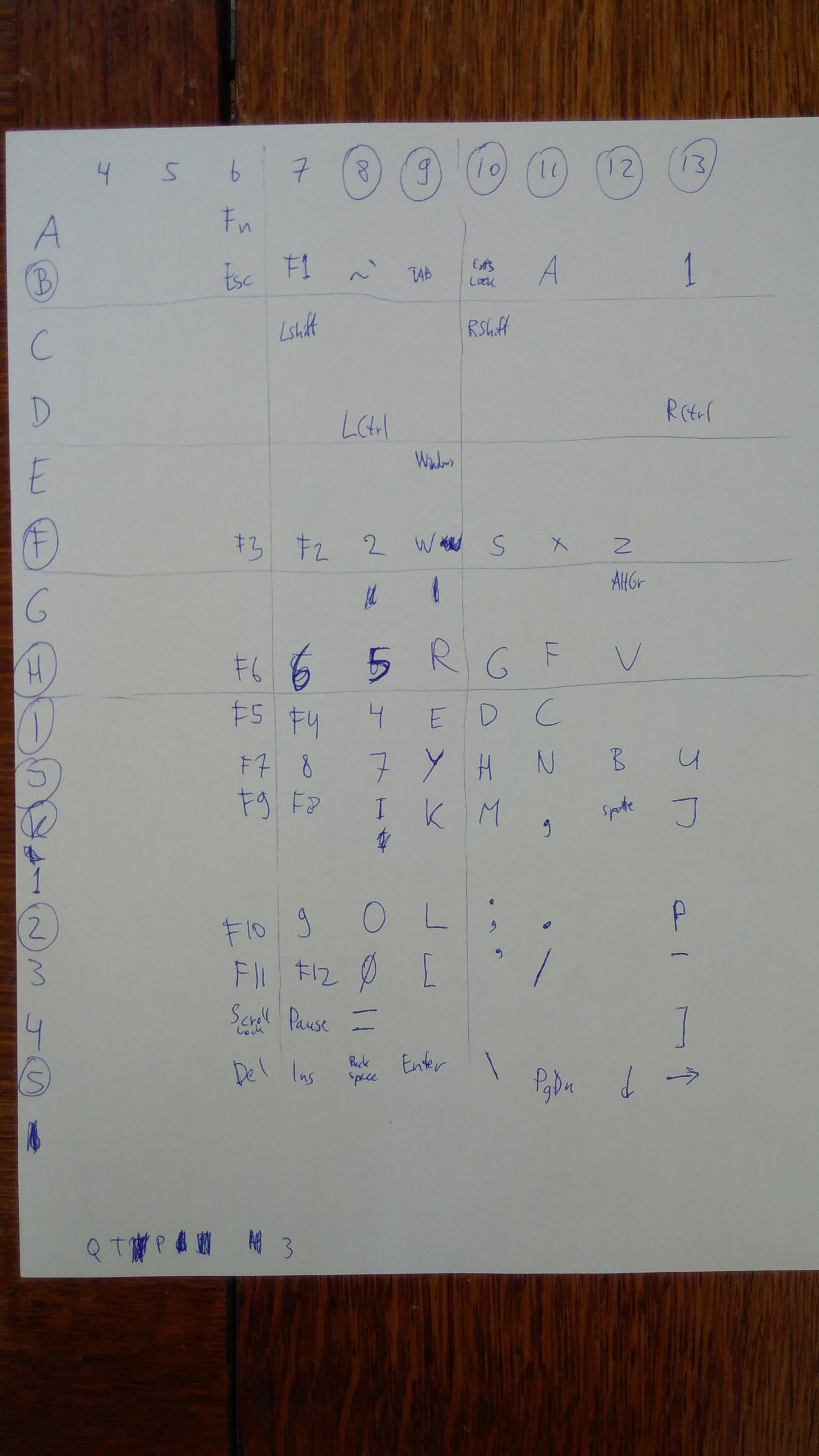
Furthermore, last night after posting, I finished my Sudoku! The Q, T and 3 are at illogical positions in the matrix, that's why I didn't find them before:
![]() As we can all see, the '1' line is left there to fool poor measurers like me. It's not connected to anything!
As we can all see, the '1' line is left there to fool poor measurers like me. It's not connected to anything! -
Figuring out the matrix
07/13/2017 at 18:43 • 0 commentsInitially, I thought: OK, I'll hack that USB board together, wire up the keyboard, do some basic analysis and then write a project log. That's been some time ago and since the part after hacking the USB board together isn't that easy after all, I decided to split the log in two.
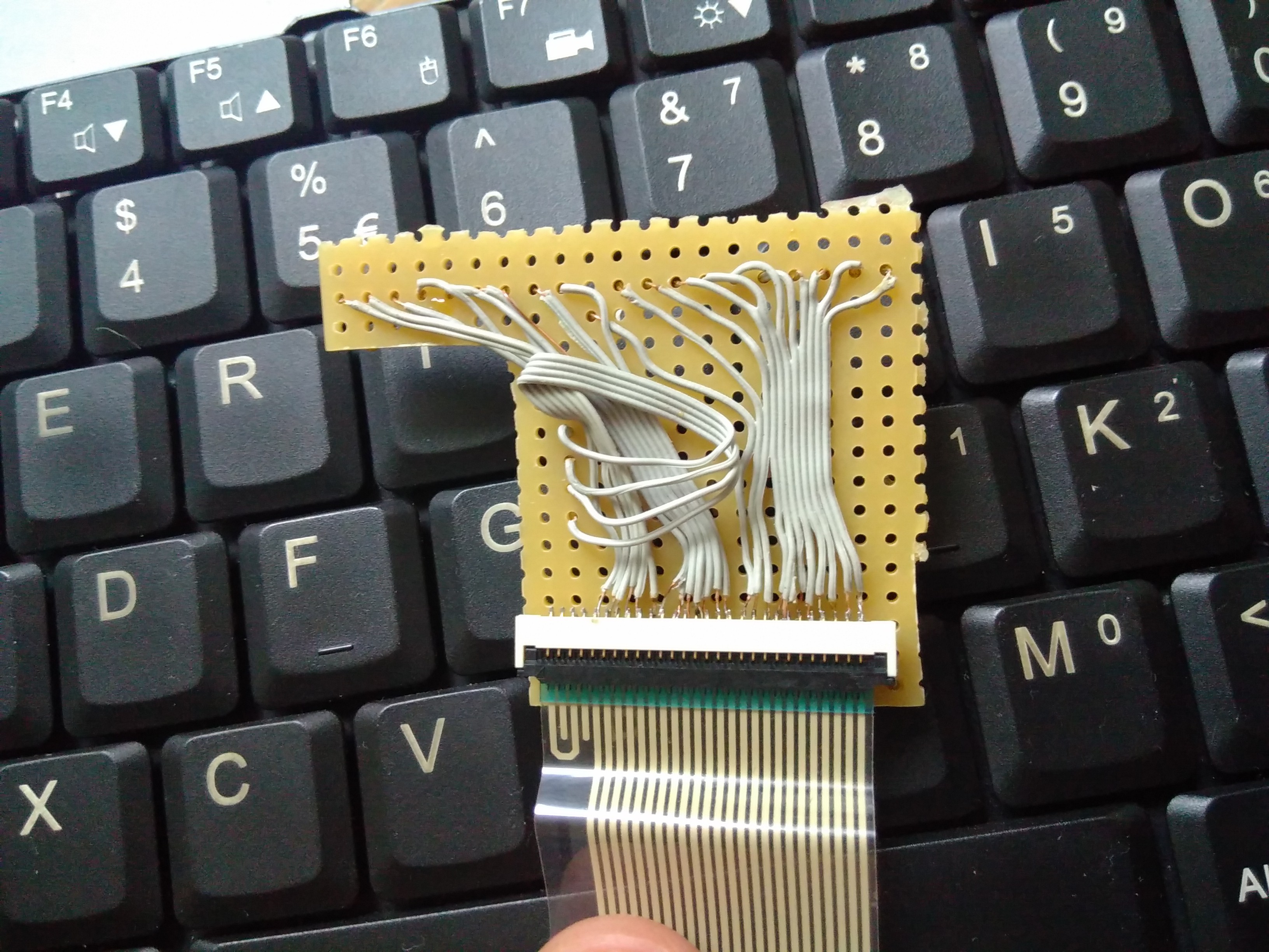
The adapter board, for a start, was a little more work than expected:
![]()
We have 11+13 wires, slightly separated at the location where they exit the keyboard. Which suggests that we have 11 columns and 13 rows. Makes... 143 keys! Nowhere near that amount of keys is found on the keyboard. And to make it more complicated, while measuring them it seems that among the 11 some are columns and some are rows.
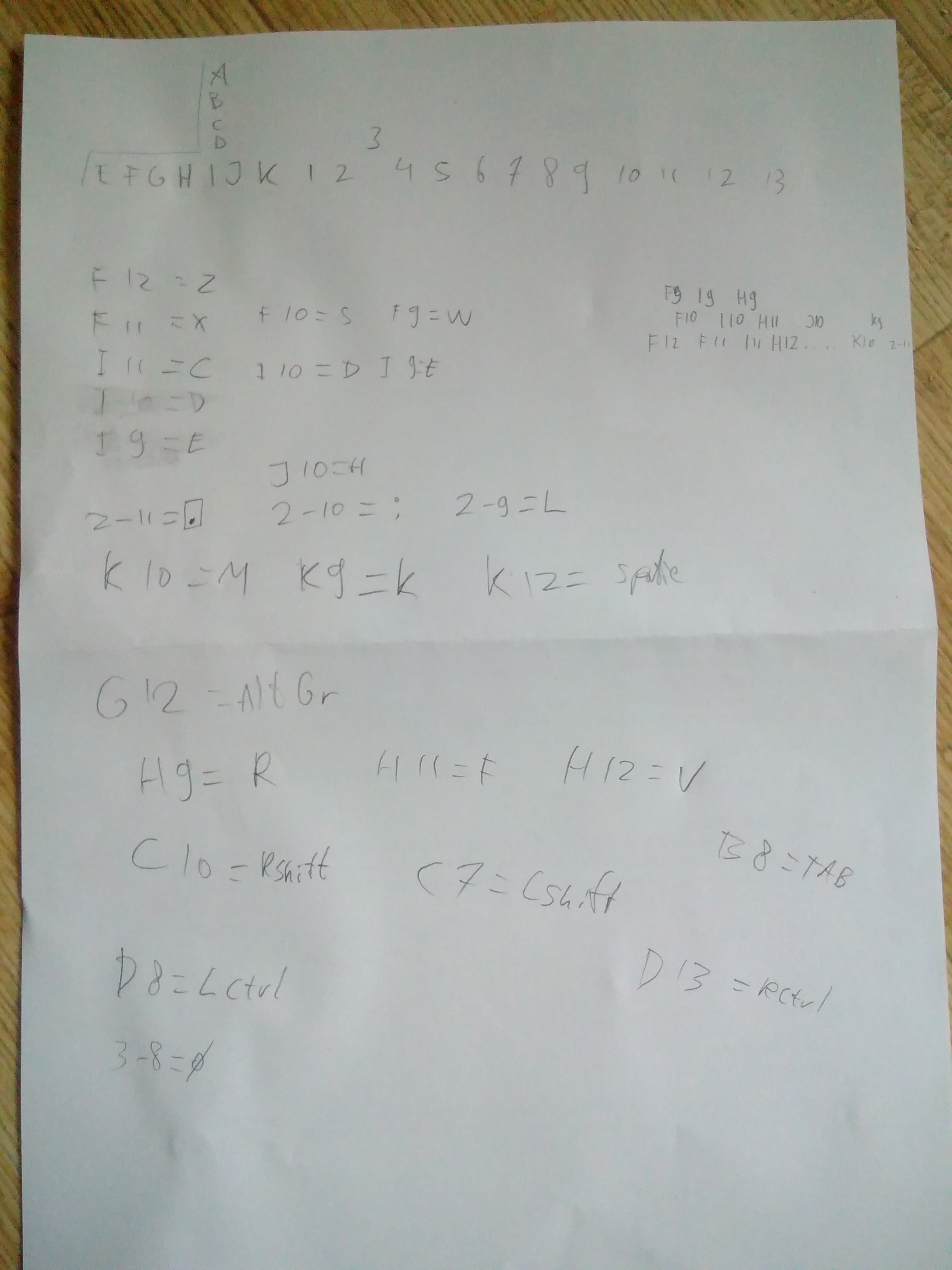
My analysis until now is this (A..K, 1..13 being the wires from the keyboard):
![]()
Initial conclusions:
- Most of the alphabetical keys are connected to the lines that I numbered 9-12.
- Some of the alphabetical keys I have not yet found (the QWERTY layout - apart from the Q which I didn't find yet - is in the top right corner as F10/F11/F12/I9/H9/etc.).
- It seems that special keys like Shift and Ctrl have dedicated rows just for themselves.
- I found the spacebar at K12! Which is very nice, itwouldbereallybadakeyboardifIwouldnothavefoundit.
- As you can see, the wires are very close together on the connector. Before I fixed a few loose wires, I did get measurements on column J for several keys. After fixing the loose wires, these measurements are gone for the exact same keys...
- A clip connector is very useful when you need three hands. However, it's not very reliable on single PCB contacts that are closer together than the width of the clip connector.
So, well, further work needs to be done...
-
Hardware!
07/13/2017 at 18:30 • 0 commentsFor Hardware I'll use an ATmega8.
Circuitry is based on https://github.com/baerwolf/USBaspLoader
With this diff:
zeekoe@teunedesktop:~/code/USBaspLoader$ git diff
diff --git a/Makefile b/Makefile
index 21e5b75..3904aff 100644
--- a/Makefile
+++ b/Makefile
@@ -8,7 +8,7 @@
 include Makefile.inc


-all: do_firmware do_updater
+all: do_firmware

 flash: firmware
        $(MAKE) -C firmware flash
diff --git a/Makefile.inc b/Makefile.inc
index 537444f..d2f09d5 100644
--- a/Makefile.inc
+++ b/Makefile.inc
@@ -37,6 +37,7 @@ DANGEROUS=0

 # PROGRAMMER contains AVRDUDE options to address your programmer
 # PROGRAMMER = -c pony-stk200
-PROGRAMMER = -c usbasp
+PROGRAMMER = -c usbtiny

 #  since USBaspLoader supports HAVE_BLB11_SOFTW_LOCKBIT...
"Schematics" from the docs:
USBD+ (green) --> PIN4  (PD2)       (usually INT0 PIN)
USBD- (white) --> PIN13 (PD7, AIN1) (new since Rev.3)

BUTTON SWITCH --> PIN12 (PD6, AIN0) (new since Rev.3)
The USB port is connected with zeners to be able to run the uC at 5 V. Not sure if this is really necessary, but it's not spec'd-but-will-probably-work for <4.5 V and I thought I had enough challenges.
The USB part with zeners looks a lot like:
https://dicks.home.xs4all.nl/avr/usbtiny/
Except on diffent pins. Sorry, I'm lazy for now... Perhaps a full schematic will follow, but you'll get the idea.
The ATmega has the option of locking the bootloader. The boot loader is stored at the end of the flash, and when you don't lock it and flash a program of >6K your bootloader is screwed. I didn't manage to lock it using my programmer, so I have to be somewhat careful.
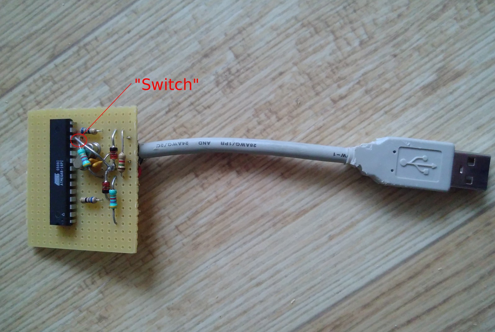
OK, so now I have this:
![]()
A circuit where I can press the 'switch' on USB insert to have it behave as a programmer to program itself.
Looking for reference firmware for keyboard, the best thing I could find was something I made a while ago: http://tuxgraphics.org/electronics/200810/avr-usb-slideshow-presenter.shtml
A two-button keyboard. I have one 'button' (the same as used to put it into programming mode), hacked the firmware a bit to use this button, and it worked. A good base to start diving into the keyboard matrix.
-
Ingredients part 1
06/17/2017 at 19:58 • 0 commentsThe ingredients until now are:
- a Fair phone 2
- an USB OTG 3 port hub with combined card reader (just because this was the one I could find 2nd hand... :))
- a Lenovo Displaylink USB to DVI adapter
- a laptop that's too old to run windows, and has too unsupported hardware to run Ubuntu. Perfect for scrap heap... or this project.
- for now, a mouse and a keyboard to test all# su # wm density 240 (or 160) # wm size (have to find out exact size of monitor)
...gives a much better look on a large screen. density 160 makes my launcher crash, but would mean that a 'density indepentent pixel' is equal to a real pixel. Normal density is 480 for this (and most Android HD) screens.
Without rebooting, some parts of Android are a little bit confused.
Good! Basics are working.
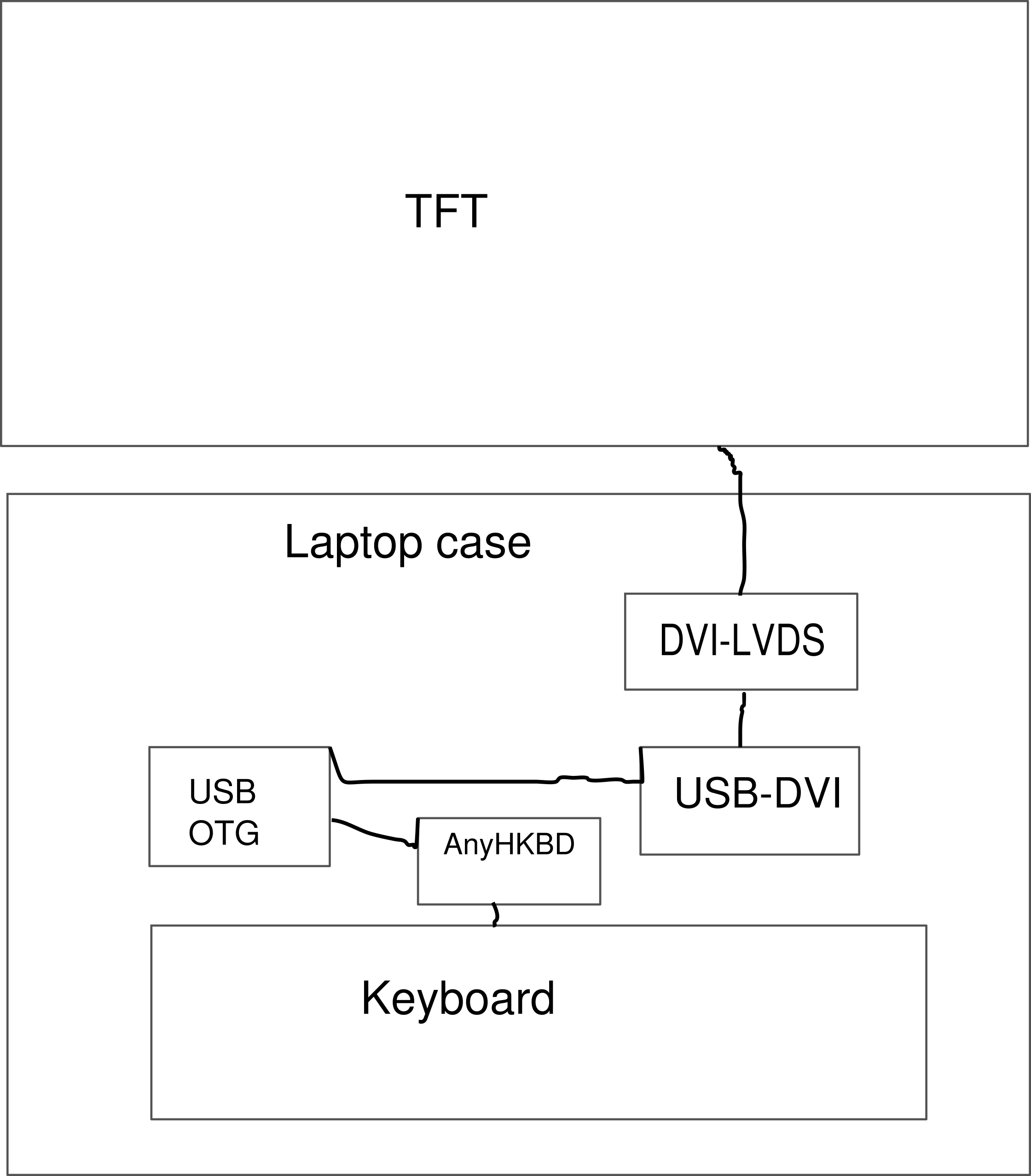
[edit] - the pan in a schematical view:
![]()
From the insides of the laptop case, the old electronics can be removed. They will be replaced by a custom keyboard driver board (AnyHKBD) which will be created in this project. The TFT will be driven by a chain of USB-DVI and DVI-LVDS boards - hopefully. An USB OTG hub will make everything connect to the phone. All should nicely fit in the empty shell.
As for the trackpad... who needs that, we have vim, right? ;-) This will be solved later. A trackball is also an option, or something PS/2 connected to an USB-PS/2 adapter. For now, I'll focus on the other parts.
Next steps:
- USB to keyboard adapter, I'll probably make this with an ATMega8 or 16 and V-USB. Have to decide what project to pick as a base for this.
- Find out if I can drive the LCD of this laptop with some DVI to LVDS driver board from eBay.
Scraptop
Laptop made out of scrap - Combined with a FairPhone2 a possible step in the journey toward a fair laptop.
 As we can all see, the '1' line is left there to fool poor measurers like me. It's not connected to anything!