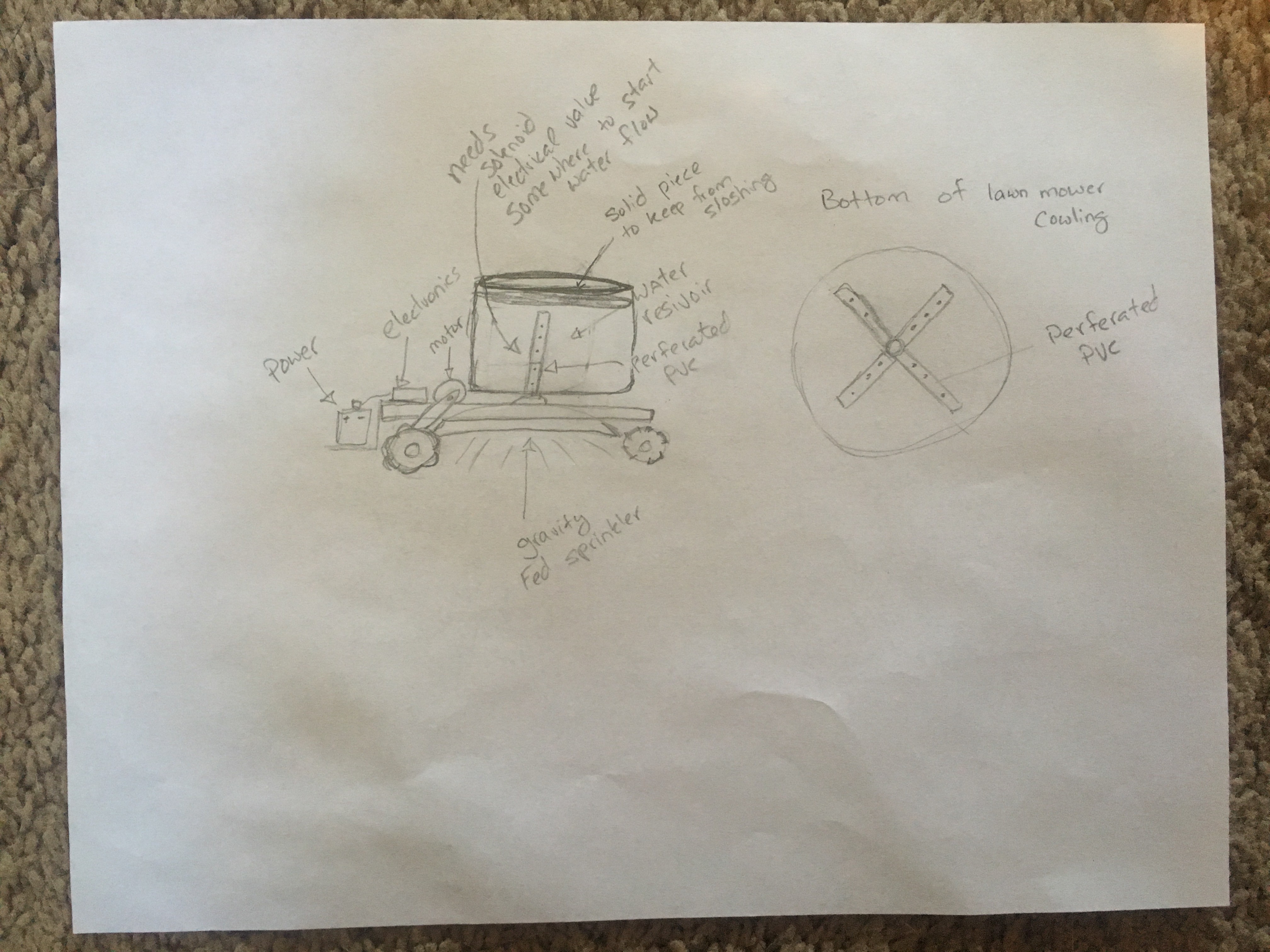
Conceptual Drawing For the Water Bot
To make the experience fit your profile, pick a username and tell us what interests you.
We found and based on your interests.

WB_CircuitDiagram.pdfKicad schematic of the waterbot circuitry.Adobe Portable Document Format - 80.32 kB - 07/24/2017 at 15:19 |
|
|
After putting the valve and various PVC fittings together I noticed that the sprinkler bar was well below the wheel well. After measuring, I determined that the bin and plumbing assembly had to be lifted about 6 inches. I didn't want to add that much weight to the bot so I constructed the platform to lift the bin out of fence boards ( 1"x6"x6"). The fence boards are extremely light and durable, readily available and are reasonably priced. Once the platform was constructed I cut a whole for the plumbing and installed small pieces of angle iron braces to hold the bin in place.
Since this project is all about watering the lawn, I thought it would be a good idea to see how well a gravity fed system would work. In order to perform a truly empirical test, I decided to test the water flow independent of the bot. I plumbed the storage container (i.e. plastic storage bin) to the valve, that will be driven by a relay in the final bot construction, to the sprinkler t-bar. I was surprised that the pressure and flow with a full tank of water was almost identical to the last inch of water. While the tank was draining I started a timer to determine how much of the lawn could be covered within 'x' amount of time. It drained 40 gallons in about 40 minutes, so around 1 gallon in a minute. Of course, I don't know how fast the bot can move so the coverage is still an incalculable value but were getting closer.
Here is a video of the water flow :
Tonight I mounted a split axle onto the base of the bot for easy maneuvering. The wheels are slightly bigger than the front wheels, thanks to the suggestion given by [dohabandit] in the comments. The gears for turning the wheels are also secured to the axle via a key and hex screw. Eventually, the gear on the axle will attach to the motor and be able to move independently for better turning and more finite control.
As I mentioned in the previous post, the FET's on the H-Bridge got ridiculously hot after a very short amount of time. To rectify this, I constructed a heat sink out of angle aluminum and a lot of thermal paste. Since the heat sync spans all of the FET's I made sure to put rubber gaskets and insulation on the FET's themselves in order to prevent an electrical short.
Building the circuit was pretty straight forward. I uploaded the Kicad schematic for anyone that is interested. This part of the build did uncover some unforeseen issues. The H-Bridge manual was completely written in Chinese, so I scoured the internet for information. I thought I had a good understanding of the bridge until the FET's became insanely hot during brief testing. Of course it goes without saying that buying some thermal paste and constructing a heat sink are in my immediate future. In addition, the solenoid for the water valve pulls 12v and 2 amps ! I don't want to drain my battery on a water valve so I will need to drive the power with a relay. Since each wheel needs to move independent, I need the sprockets mounted to the tire to transfer the force. However, the sprockets for the tires are not easily mounted to the tires. Mainly because the size of the sprockets in relation to any mountable surface.
Here is some photos of the circuit prototyping:
The frame is looking pretty solid now. I think I am going to switch gears now and start writing the code for the esp 32 micro controller. Once I have the circuit and the code working, I will start mounting the motors, sprinkler system, batteries, etc.
Wanted to see if the bot could hold weight since the end goal is to carry a fair amount of water, plumbing, electronics, batteries, motors, etc.. Not to mention it was pretty fun ;)
Started the mechanical build for the waterbot, fun to actually see it coming to fruition.
I am still waiting for my components to come in, so I decided to write the app to interact with the ESP32. I will be using the app to test my code and to eventually drive the bot. Currently it is on my own private network but eventually I can add a dyndns address to control it remotely.
While I am waiting on my components, thought I would do the math to figure out how fast the bot would travel carrying 50 gallons of water (400 lbs) in a reservoir.
Wheel size: 6 inches diameter.
Wheel size sprocket:3 inches OD.
Motor size sprocket:2 inches OD.
Reduction ratio: 1.5 to 1
Target water weight: 400 lbs (50 gallons)
Torque rating of the (50rpm) motor = 8ft-lbs.
Torque to drive the wheel: 8 ft-lbs x 1.5 = 12 ft-lbs.
Convert units from ft-lbs to in-lbs: 12 ft-lbs x 12 = 144 in-lbs.
Convert to force: 144 in-lbs / 3 in = 48 force lbs
48 lbs force: traction of one wheel
Maximum traction for two wheels: 48 lbs force x 2 = 96 lbs force
96 lbs force = 427 N (Newton)
6 in = 0.152 meter
400 lbs = 181 kg.
427 N = 181 kg x a and a = 2.36 m/sec^2
50rpm / 1.5 = 33.3rpm = 0.556 rev/second
0.556 rev/second x 6 in x Pi = 10.5 inch/second = 0.267 m/s (final speed).
2.36 m/sec^2 = (0.267 m/s - 0 m/s) /0.11 s
Conclusion:
400 lbs robot should be able to move from static to 10.5 inch/second in just 0.11 second.
** Probably slower because I didn’t account for debris / rubble on the ground, uneven surface, etc … also, climbing a slope may create issues as well.
Of course, 50 gallons is the end goal. For the initial build the reservoir will contain only 35 gallons of water ( 280 lbs )
Create an account to leave a comment. Already have an account? Log In.
I think this kind of ideas are really impressive and useful specially in the coming days you can click bathroom faucet where you can see some similar kind of products.
Cool project Mary. I'm planning on building something similar. We have a lot of trees and grass to water on our farm. How is the project coming now?
Cheers Max
Hi Mary! Great project... I was wondering if I could offer some modifications to the 50 gallon water tank situation and the need of LAWN GPS. There is DGPS that allows for precision GPS but is expensive. I was thinking of something else to track Water Bot around the lawn. Here is my conceptual diagram. It's rough but conveys my thought process I hope...
http://www.upl.co/uploads/waterbotwithlawn-gps1515085340.jpg
This is an awesome solution to a complicated issue ... thanks! I will try and integrate it into the "2.0" version.
ty - I was thinking that the 50 gallon tank may be a bit too top heavy and may dump over. So how about loosing my gravity tower idea and installing a 12 volt water sump pump to send water to the sprinkler head under the water bot. You'd need a 12 volt car battery on the water cart too. Also leave the cart on pavement or driveway to avoid it's small wheels from bogging down into the lawn. The water bot could still navigate well on lawn without the weight of a water tank on it's back,
The IR LASER tracking will take some really deep HaD engineering skills in that you will need a bi-directional stepping motor for azimuth turret, an Arduino to process tracking data, an IR LASER, and a photo-diode to pickup the reflector on the water bot. The Arduino would give you distance to target in meters and the direction in degrees horizontal azimuth. You could over-kill with elevation return if lawn is very big.
Those numbers would allow you to display a position of water bot from the known position of the water cart on a lawn map. Sounds easier than it would actually be. There must be a better and simpler tracking system like some sort of inertial navigation system with turn by turn detection and distance odometer tracking. The Arduino could then measure the water bot position based on it's known starting position on the lawn to it's new position inside the lawn somewhere.
The odometer could be a electronic wheel measure in where you know the exact distance each click represents, and the turn detector is a potentiometer (fed into a/d convertor) on the steering mechanism that measures how many degrees (via ohms) deviation from zero degrees forward bearing. Or to keep it digital the turn detector could be a optical encoder disk and photocell like from a PC mouse.
(NOTE: Inertial nav is a system that measures distance you travel in first direction, then start over at zero every time you change direction, then maps out all those turns and distances on a map display without using any external device like compasses, gps, etc. - you don't even need to see where you are going like in a submarine - you still need collision avoidance though)
I'm sorry if I'm over-simplifying very complex concepts...
I just thought of this idea the other day, you beat me to it!
I wanted to use something like this to water my lawn. I have a lot of trees which means lots of roots and that makes running lines for irrigation very difficult. My thought was to have a charging and refill station somewhere in my yard so that the bot could fire up at night and make its rounds around the yard watering - fully automated. My only concern is if the bot accidentally ventured into the road in front of my house and someone hit it.
Yeah, future enhancements are to put in a low water notification mechanism. So that it can send me a text when I need to fill it up. We have a 400 gallon cistern on the property, so grey water is not an issue but like you we have a large yard ( 3 acres) and a ton of oak trees. So another future enhancement is going to include a mapping function. The idea would be to map the front, side, back yard and let it water autonomously. That should take care of it not running into the road or in the third world areas the bot would not waste water where it doesn't need to run.
Pretty much exactly what I've had in mind. Have you given any thought to how you will accurately map? I've not done any research in a while, but last I knew GPS was only accurate within a few feet if you are lucky. My thought was to make some stakes that go into the dirt that have BLE modules in them with a battery. Then use them as landmarks to create the map.
You are correct GPS is not useful for granular position. My first attempt wasn't going to be so sophisticated I was just thinking of recording the movement as I drove it around with my iPhone then just play it back like a script. (i.e. -- forward 1 second, turn right, forward 1 second, turn left ...) Your idea is interesting, hadn't thought of that approach. Also thought about burring wire and doing the roomba thing but both methods could be impractical for watering in places around the world. As you can tell I need to think through it a bit more ;)
Mary, you should consider the characteristics of your bot before getting too far along with a chassis build. Water is very heavy. You have a heavy frame and you have small wheels that will spread that weight over a small surface area. Unless you are watering hardened surfaces, it is likely that your bot will struggle to move around on grass/dirt/sand environments.
Take a look at other garden/tractor bots. Using larger/wider wheels would be a good start.
Thank you for your insight. I will look into more designs to make sure my design will withstand the weight. For the prototype I am building, the water weight will be around 184 lbs for 23 gallons of water. A fraction of the end goal of around 400 lbs or 50 gallons. I have already learned a bunch on this build and am sure I will learn a lot more, any comments are much appreciated. I don't want to wind up on "Fail of the Week" .
Have you considered having the water release solenoid interact with the stop/brake to ensure that the water release doesn't continue while the bot has stopped?
No, that is not a use case that I had given any thought too. It definitely makes sense to not waste water when the bot is stopped. Thanks for the suggestion !
Hey, you guys should seriously consider using a rust converter on that sweet chassis. Don't think it can do any harm....
I did wind up using a rust converter and then applying a high gloss enamel paint. Of course that was after hours of sanding down the rust and prepping.
Become a member to follow this project and never miss any updates
 Brandon Hart
 Fabio
Fabio
 Josh
Josh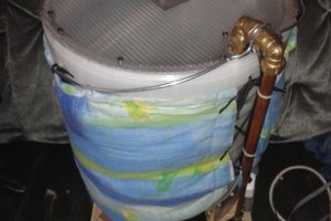
 Morning.Star
Around the globe, the threat of drought is ever increasing. The water bot was created to address water conservation by limiting water to the size of a catch basin.
You can check water proofing tips to save water.
https://homeadvisor.com.pk/services/waterproofing-services/"