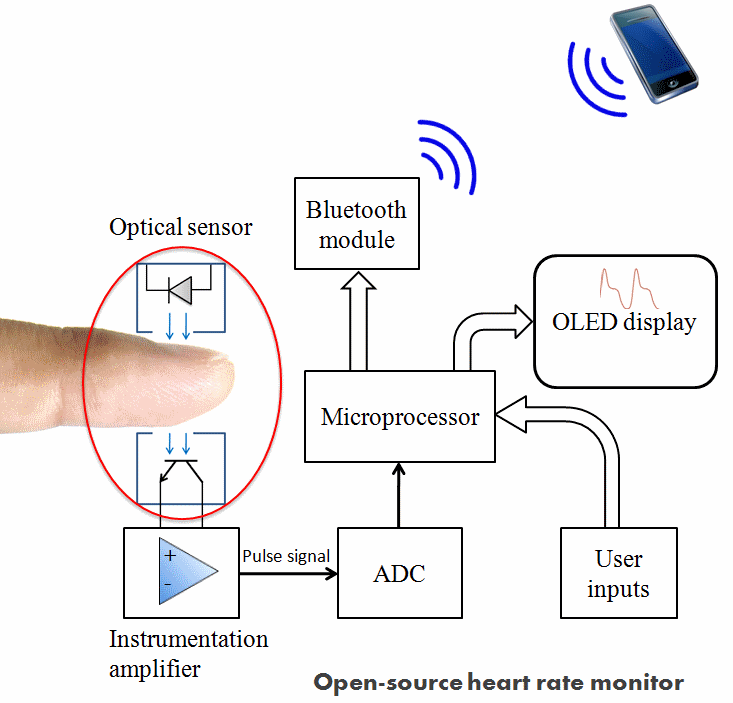
System design of the project.

The following video describes the functional block diagram of this project.
An open-source heart rate monitoring system based on the photoplethysmography principle.
To make the experience fit your profile, pick a username and tell us what interests you.
We found and based on your interests.
System design of the project.

The following video describes the functional block diagram of this project.
The ADC block and microprocessor in the system design (described earlier) will be replaced by a single microcontroller with built-in ADC. This will simplify the design and reduce the cost. I am still debating with myself about choosing between the Arduino and PIC32 microcontroller.
Filtering and amplification of the raw PPG signal is required to match the signal characteristics with the ADC specifications. I am currently working on an operational amplifier based active band pass filter to get rid of noise and boost the PPG signal. I will update this section soon.
I quickly setup a simple biasing circuit on a breadboard to check the raw pulse signal from the HRM-2511E sensor. Here's my circuit setup for this test.

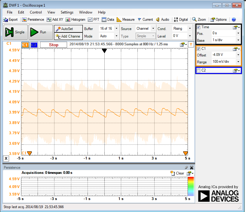
I observed the waveform of the raw pulse signal output (Vout) from fingertip on my PC using my Analog Discovery tool from Digilent. The pulse signal waveform has amplitude of a few millivolts as shown below. This waveform was generated by wearing the sensor on my index finger.

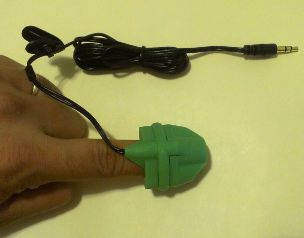
I am going to use the HRM-2511E fingertip pulse sensor manufactured by Kyoto Electronic Co., China in the prototype of this project. I have worked with this sensor before and I have found it very easy to use, and provides stable output. The HRM-2511E sensor body is built with flexible Silicone rubber material that fits nicely on the top of a finger. Inside the sensor case, an IR LED and a photodetector are placed on two opposite sides and are facing each other. The necessary connections to the LED and photodiode pins are available through a 3.5mm stereo audio connector.

HRM-2511E pulse sensor
Create an account to leave a comment. Already have an account? Log In.
Become a member to follow this project and never miss any updates